EP0610318B1 - Procede et appareil de traitement d'images - Google Patents
Procede et appareil de traitement d'images Download PDFInfo
- Publication number
- EP0610318B1 EP0610318B1 EP92922331A EP92922331A EP0610318B1 EP 0610318 B1 EP0610318 B1 EP 0610318B1 EP 92922331 A EP92922331 A EP 92922331A EP 92922331 A EP92922331 A EP 92922331A EP 0610318 B1 EP0610318 B1 EP 0610318B1
- Authority
- EP
- European Patent Office
- Prior art keywords
- specimen
- objects
- radiation
- generating images
- dimensional
- Prior art date
- Legal status (The legal status is an assumption and is not a legal conclusion. Google has not performed a legal analysis and makes no representation as to the accuracy of the status listed.)
- Expired - Lifetime
Links
Images


Classifications
-
- G—PHYSICS
- G06—COMPUTING OR CALCULATING; COUNTING
- G06T—IMAGE DATA PROCESSING OR GENERATION, IN GENERAL
- G06T12/00—Tomographic reconstruction from projections
- G06T12/20—Inverse problem, i.e. transformations from projection space into object space
Definitions
- This invention relates to three-dimensional image generation using a variety of types of interrogating radiation, including electromagnetic, particle and acoustic radiation. In particular, it finds application in the processing of images produced with X-rays.
- PCT application No. 92/20032 there is disclosed a method of generating images of a specimen containing at least two regions of different opacity to the passage of radiation comprising irradiating said specimen with radiation from a radiation source; detecting the amplitude of the radiation passing through said specimen from different directions; these amplitudes are processed to derive further signal indicative of contours of maximal local discontinuity; and generating a three dimensional boundary surface.
- the apparatus produces images of a single slice of an object by moving an X-ray camera and the image plate in a complementary manner so that everything is blurred except for a predetermined plane.
- Commercial machines produce images of a number of separate slices, moving the X-ray machine to produce a planar picture and then moving the object under test in the Z direction to produce a planar picture at different slices. That needs more total pictures than the views spread over a solid angle and it produces a cruder representation of a three-dimensional image because volume cells intermediate between slices have to be derived by interpolation.
- CT computer tomography
- Conventional tomography thus produces images of discrete slices normal to the axis of objects of short axial length. It is more common, however, to require images to discrete slices normal to the axis of a long object.
- the established form of computer tomography (CT) is designed to do this. It does it by taking a number line images, at different viewing angles in the plane of each such slice (typically 360-1440 views, taken at 1° to 1 ⁇ 4° intervals). These are then used to compute the corresponding slice image.
- the invention - and even the established form of computer tomography - is better understood by first postulating an extension of computer tomography which, unlike existing systems, would produce a true three-dimensional mapping of the X-ray densities (i.e.
- This hypothetical version of computer tomography might map a cubical volume L 3 into (L/c) 3 voxels of size c 3 .
- this postulated ideal form of computer tomography would involve L/c distinct X-ray projections, of (L/c) 2 pixels. Each pixel represents the aggregate density of a column of L/c voxels. The individual densities of all voxels are then computed by (L/c) 3 simultaneous equations. No assumptions about the features of the specimen are involved. The resulting picture is fully three-dimensional, amenable to three-axis rotation, slicing etc.
- the voxels are not independent:- signal/noise considerations require a significant degree of smoothing and integration (by the human eye or brain and/or by a computer algorithm), which causes the effective image to be composed of reasonably smooth multi-voxel elements.
- the processing may be simplified by treating an object under test as a set of component objects, each defined by one or more closed surfaces, where the precision of the surface shape of these component objects should ideally match the resolution of the sensor system. Indeed, for smoothly-varying surfaces, a least mean-squares or similar fit can produce a precision superior to that of the individual constituent measurements. Furthermore these component objects are generally of individually uniform specific density, and of reasonably “well-behaved" shape. (Complex shapes may be broken down into multiple constituent objects of simpler shape.)
- These component objects can be cross-identified, between different views, by projection on to the axis common to each pair of such views.
- Each such projection also defines the three-dimensional position of two outermost surface points of the object (as projected on to this common axis), with a precision matching that of the source pictures.
- n views generate n(n-1) such points on each object surface, and these points cluster most closely in the areas of greatest curvature on these surfaces.
- the line contour segments between the points can also be derived with considerable precision.
- This generates a network of n(n-1)+2 surface cells,
- the three-dimensional shape of these cell surfaces can also be derived with good precision. (If there are any inflexions or sharp comers or other point singularities, their position in three dimensions can similarly be identified from any two suitable projections, thus producing some additional nodes and meshes in this network.)
- the representation of the observation volume as a set of three-dimensional objects matches the physical reality. This enables the technique to cope with higher noise levels than equivalent conventional systems. It also provides a convenient basis for determining X-ray specific densities and for providing user-friendly facilities of object selection, enhancement, rotation, slicing, and general manipulation.
- the resultant picture is amenable to three-axis rotation and to slicing, just as with three dimensional pictures extrapolated from conventional forms of tomography.
- any desired subset of objects can be readily selected or deleted (or enhanced, attenuated or coloured) at the user's discretion.
- this approach gives the benefits of conventional forms of tomography - and some further user-friendly features - with dramatically fewer X-ray exposures and reduced computation.
- a method of generating images of a specimen containing at least two regions of different opacity to the passage of radiation comprising irradiating said specimen with radiation from radiation source means, detecting said radiation with radiation detector means sensitive to said radiation to produce a plurality of signals indicative of the amplitude of said radiation passing through said specimen in a corresponding plurality of different directions characterised in that said plurality of signals are processed to derive further signals indicative of contours of maximum local discontinuity in opacity or texture thereby providing an indication the position of the three-dimensional boundary surface between said two regions.
- said further signals are subject to further processing to subdivide the representation of said surface into a plurality of elementary substantially planar surfaces to facilitate the manipulation of images of said boundary surface.
- each picture element represents the aggregate attenuation due to the X-ray densities of all the volume cells (voxels) traversed by the corresponding ray.
- Such pictures valuable as they are, suffer from a number of significant limitations:-
- tomography has the same etymological root as "microtome”.
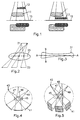
- the point-source of radiation is abovc the target object, and the photographic plate for equivalent sensor array) is below it and parallel to the desired slice.
- the source and sensor are then progressively displaced, in opposite in directions, (normally in one, but ideally in two dimensions) parallel to the slice plane ( Figure 2).
- the ray passing through any given object voxel in the selected slice plane will always terminate at the same image pixel, producing an enlarged but undistorted picture of the selected slice.
- the ray sweeps through a two-dimensional array of distinct voxels, thus smearing their contributions to this pixel into a substantially uniform grey background to the picture, which can be largely eliminated by spatial low-pass filtering.
- the contrast so achieved is somewhat limited.
- CT Computer Tomography
- a line array of sensors in the plane of the desired slice, and a point source, facing it on the opposite side of the object (Fig. 4). Both rotate through equal and opposite angles through 360°, so that views through that slice can be taken, typically at intervals of 0.25°. (In principle, 180° rotation would be sufficient but, with divergent sources, reciprocal views are not identical, and continuous rotation, possibly .
- each ray In each view, each ray generates, in the corresponding sensor pixel, a signal which defines the aggregate attenuation due to all the voxels (within that slice) traversed by the ray.
- a 1,000-point sensor with a 1,000-point resolution along each ray, can then produce a 1,000-line (10 6 pixel) image.
- this requires 1,000 independent exposures to collect the necessary data.
- Each image pixel then gives the sum of 1000 such voxel densities.
- this aggregate density of around 5000 with an accuracy of ⁇ 0.5, i.e. a signal/noise ratio of 80dB.
- Each slice undergoes 1000 such irradiations, thus exposing the patient to a total radiation dosage which is at the limit of permissible risk, acceptable only in case of critical medical need for the information.
- each slice requires the determination of one million unknown voxel densities from 1000 simultaneous equations of 1000 terms each, normally using a specialised array processor.
- Computer tomography produces very high-quality two-dimensional images, with a resolution, typically, of 1000 lines.
- the third dimension depends on the interpolation between slices. Normally 30 or 40 slices are taken; very exceptionally this might be increased up to 100. However, the inter-slice spacing can be adjusted so that the set of slices just brackets the region of interest.
- the computer tomography source beam has been broadened somewhat in the axial dimension, normal to the slice, and the sensor array has accordingly been widened from a single-line array to an elongated rectangle, so as to yield full, uniform three-dimensional resolution within slices of moderate width, and so - via multiple slices - in the whole volume of interest. This, of course, increases the computational load and data-storage requirement even further.
- An object-based scenario is excellently matched to non-medical applications, such as industrial inspection, and security inspection at airports etc. It is also an adequate representation of a high proportion of medical applications, particularly orthopaedic ones.
- This object-nature of our subject material is the basic assumption underlying our approach. In fact, we do not depend on the source material being very simple in shape:- Any pronounced change or of projected density - or of texture - will be treated as an interface to another "object”.
- the scheme can also accommodate objects of spatially varying density, or indeed some totally non-object-like material.
- An object is any region in space enclosed by a discontinuity in density or texture.
- Each projected view of an object generates the corresponding outline, in the image plane. Any pair of such image planes intersect on a common axis. Hence we can identify, on both views, the extremities of the object as projected on to this axis. ( Figure 6). (These points correspond to the intersection of the two outline loci on the real object.)
- two 'common points' 61-63 whose two-dimensional position is known in two distinct planes, and so we define their position in three dimensions.
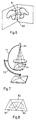
- the viewing axis of the source 43 and diametrically opposite two-dimensional sensor 41 can be steered in one angular dimension by rotating the inner arc 71 of Figure 7 about a horizontal axis, similarly to existing computer tomography equipments.
- the second dimension is obtained by rotating either the platform on which the subject rests or the outer arm 73 of Figure 7 about a vertical axis.
- Figure 9 uses the specific example of a source 91 at 20° elevation, with an angular spread of ⁇ 15°, to illustrate how sources can be positioned in the upper angular hemispheres to avoid obstruction of their radiation by the sensor arrays in the lower hemisphere. If the sensors are to face exactly towards the relevant source, each source must have its own sensor array.
- the configuration of sources and sensors is preferably matched to the largest volume needing to be viewed simultaneously: as a (somewhat extreme) upper limit, say, an ellipsoid of 90cm (length) by 60cm (width) by 40cm (depth).
- a (somewhat extreme) upper limit say, an ellipsoid of 90cm (length) by 60cm (width) by 40cm (depth).
- the spread of the source beams can be restricted by suitable irises.
- the dominant length dimension determines the source-to-subject and subject-to-sensor spacings.
- the biggest source-to-subject spacings could however be roughly halved, if, of our ten views, those substantially normal to the length dimension (say 4 - 6 views) were covered by 2 distinct (sequentially excited) sources each, and by two half-length sensor screens.
- the subject-to-sensor distances are however determined by the viewing angle ⁇ , and so are: unchanged.
- This configuration also reduces the ratio of major-to-minor axes in the source irradiation angles, and would reduce the side-scatter "noise" in the resulting picture. It may also be possible to narrow the source X-ray beams in one angular dimension and then to step scan them to restore their angular cover, thus permitting a further reduction in side-scatter noise. The sizes of the arrays would be matched to the projected views of the ellipsoid.
- the average view would require approximately( ⁇ /4)(1000/90) 2 (90 ⁇ 60 ⁇ 40) 2/3 angular cells, i.e., for ten views, a total of 1.4 million resolution cells to be separately read, e.g. from a photo-stimulable storage phosphor (like the "Fuji plate").
- the interogating laser beam should be in line with the primary radiation beam. It will, furthermore, be necessary to have a separate plate for each viewing location.
- a small part of the screen might even be common to three views, differing in two angular dimensions. However, as a rough estimate, 80% of elements will serve two views and 20% only one view. This corresponds to a 40% saving, giving a total of roughly 8.5 million resolvable elements on the screen.
- These elements can form a common sensor screen, covering the full solid angle of 2] in a continuously-curved surface. This surface does not need to be hemispherical, but may be suitably matched to the shape of the limiting ellipsoid. With time-sharing where necessary, subsets of this screen can cater for any number of views or any change of viewing angles, given the appropriate number of additional sources or source positions.
- n(n-1) surface points are interconnected by a network of 2n(n-1) line segments whose three-dimensional track we can infer, with high accuracy, from their known end-points and their known projected contour.
- the first outline drawn on a closed surface divides it into two regions. Each subsequent outline crosses each pre-existing one twice, and so adds two mesh-cells per pre-existing outline.
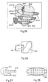
- this network will define the surface as a set of n(n-1)+2 mesh cells 121. ( Figure 12). Most of these cells will be bounded by 4 line segments, but some will be triangular and some may have 5 or more sides. However, in all cases, two projected contours intersect at each vertex, so forming four quadrants. Hence these cells may be found as follows:-
- the sides of the cells so formed will generally be curved and, in a cell of four or more sides, the comers will not normally be coplanar.
- the four points are the basic mesh nodes; the other eight points arise from the three-line approximations.
- an originally four-sided mesh is represented by ten, and a three-sided one by seven triangular facets.
- This representation yields dramatic savings in computation for image manipulations, such as rotation or slicing.
- we can smooth the resulting surface, and so obtain an excellent reproduction of the continuously-curved real surface.
- Item 1. implies that an abrupt excrescence or cavity in a single functional entity would split it into two distinct 'objects', in each projected view, and hence in the derived three-dimensional representation.
- the data analysis will note the common interface.
- in an excrescence it will note the common specific density, and in a cavity the reduction of the specific density to that of the filling medium, if any. (In many cases, the cavity may in fact be treated, as a projection from an adjacent physiological entity.)
- the mechanisms listed above will normally generate a rather fuzzy and noisy representation of an object's edge. In order to obtain a best-estimate sharp outline, and to condense the data into an amenable format, we convert the input data into a concatenation of 'least mean square error' second-order polynomials.
- the span length of these polynomials is adaptively adjusted, in constant-ratio steps, to keep the error within specified upper and lower limits.
- the starting point of each polynomial is the end of the previous one, and the end-point is the mean of the 'raw' edge points within a specified limit of the postulated span length from that start. This process is automatic, but with provision for optional operator intervention.
- the first step is to find all edges and to represent them as chains of 2nd order polynomials.
- the principal tool for resolving cross-over ambiguities is a local density comparison.
- the points being compared should lie on parallels to the relevant edges, to be on probable equidensity contours, but not too near the edge, where the density gradient is maximum and measurements would be error-prone.
- This overlap resolution process is performed in each of the ten or more views.
- the common identity of a given object is maintained, from view to view, by noting the common locations of its extremities (and of other key features), as projected on to the axis common to a pair of views.
- the same process can also be used to resolve any doubt, when analysing potential overlaps in a specific view, e.g. to establish whether a high-density region on one view is a small object in its own right, or is the result of an overlap between too larger objects. If, exceptionally O(p,1), i.e.
- object p in view 1 cannot be directly identified with O(p,2), it should certainly be identifiable via one or more intermediate views: O(p,1) ⁇ O(p,x) ⁇ O(p,y) ⁇ O(p,2).
- the position of the sampling rays is determined, primarily, from superimposed outlines in the plane normal to the proposed ray direction. It is chosen, by inspection or analysis, so that:-
- the triangular facets penetrated by a sampling 'ray' may be identified as follows:-
- Density mapping is desirable mainly because of its familiarity from conventional X-rays. With our full specification of the three-dimensional surface of each object, we can easily select only wanted objects, discard those that obstruct the desired view or show only their outline, producing a transparent projection of multiple overlapping objects.
- Every-day experience is best matched by opaque projection where a nearer object obscures any more distant one.
- the relevant objects are normally represented by their outline, with appropriate distinctive colouring or patterns, or by their simulated surface reflectance.
- a subset of objects may be identified, from the variance of their initial, single density value, as being of variable density.
- These objects (or at least the sub-subset designated by the operator as of diagnostic importance or others, where the covariance shows that they affect objects of diagnostic importance), can be treated as an array of cellular subobjects with independent cell-densities.
- the density variations are relatively smooth, since any abrupt discontinuity would have generated an 'interobject' boundary.
- the resolution for mapping within-object density variations can be substantially coarser than that defining the object's surface.
- k which, roughly, represents the number of distinguishable density steps per linear dimension:-
- variable-density object with 1000-cell boxes would only increase by 10% the total storage requirement for a fixed-density objects, with ten views (See analysis below and Table 8).
- the regular array of cubical cells is very convenient for creating views parallel to any desired axis.
- variable-density objects there should normally be substantial scope for averaging over groups of associated input pixels, and for taking redundant independent density samples, in order to enhance the signal/noise ratio in determining the individual cell densities.
- a wide-fan computer tomography system with a 10 6 -pixel slice-plane resolution, a slice width of 20 voxels, and a total of ten slices, would have a total input of 2x10 8 density words.
- the dominant computational load is that of resolving the densities of the constituent voxels or pixels, respectively, and so is directly proportional to the input data, above.
- the computation is mainly dependent on the number of primary surface points generated (i.e. excluding the 3-line approximations). This is estimated below to be 400 points per object.
- These computations have of course to be weighted by distinct scale factors:- For the computer tomography systems the quantity of computation per voxel is greater, but for the object-based scheme the complexity of the computation is greater, and so it is less suitable for a specialised array processor. For the present, we ignore these differences.
- 10/d is a more realistic figure, resulting in 10V 2/3 n 1/3 surface voxels.
- position could be implied by storing all voxels in a predetermined pattern.
- the storage requirement is only reduced in the ratio 40/(V/n) 1/3 .
- Standard computer tomography has less input information and very crude information in the axial dimension (and accordingly fewer but larger voxels).
- the ratio of edge pixels to total pixels within a slice is then the same as the voxel ratio above. In this case, however, each pixel needs only two position co-ordinates in addition to the density, and so reduction factor is then 30/(V/n) 1 .
- each object involves, 90 contour intersection points per monotonically curved object surface. Making a generous allowance for possible complex re-entrant shapes might increase this total to, say, 400 points - plus a further 800 points arising from the three-line approximations, all associated with three position co-ordinates.
- Let us allow for an average of four pointers linking these points to the storage addresses of other points and, for the contour intersections only, four pointers to the associated mesh cells. (The various pointers, whilst not essential, can save much subsequent computation.) This gives a total of 10 4 n words. (On the same basis ten views of n objects, with the nodes joined by single straight lines, would require 4x10 4 n words.)
- the scheme need not be limited to X-rays: it can be applied to any transmission-type imaging systems, such as: infra-red or neutron radiation, and positron emission.
- conventional X-ray tomography, computer tomography, acoustic imaging, and magnetic-resonance imaging all generate their information as a stack of cross-sectional slices. On each of these slices, edges could be detected and objects outlined, as in our process. These edges can then be defined as a succession of straight-line segments, and the corners of a given object, in consecutive slices, can be joined to create triangular facets, as illustrated in the next section.
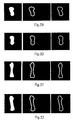
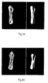
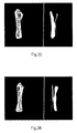
- Figures 29-36 show four different views of (a) the raw X-rays of a nylon bone (b) the edges extracted from (a) and (c) the multiple-polynomial graphical representation of (b).
- Figures 33-36 show (a) 3D wire frames of the nylon bone at different orientations reconstructed from five raw X-rays and (b) renedered views of (a).
- n 1 10 100 1000 Wide Fan CT 2x10 8 Normal CT 4x10 7 Object 3D 1.2x10 3 1.2x10 4 1.2x10 5 1.2x10 6 Comparison of Processed (Surface-only) Data.
- n 1 10 100 1000 Wide Fan CT 4x10 6 9x10 6 20x10 6 40x10 6 Normal CT 0.6x10 6 1.3x10 6 3x10 6 6x10 6 Object 3D 10 4 10 5 10 6 10 7
Landscapes
- Physics & Mathematics (AREA)
- General Physics & Mathematics (AREA)
- Engineering & Computer Science (AREA)
- Theoretical Computer Science (AREA)
- Apparatus For Radiation Diagnosis (AREA)
- Image Processing (AREA)
Claims (38)
- Procédé basé sur un objet de production d'images d'un échantillon contenant au moins deux objets comportant des régions d'opacité différente au passage de rayonnement, comprenant : la projection sur ledit échantillon d'un rayonnement issu d'une source de rayonnement ; la détection de l'amplitude du rayonnement passant à travers ledit échantillon à partir de directions différentes ; l'obtention à partir de ces amplitudes d'un signal supplémentaire représentatif de contours de discontinuité locale maximale ; et la production d'une surface de frontière tridimensionnelle, caractérisé en ce que ledit procédé comprend les étapes de projection sur ledit échantillon de rayonnement provenant d'un moyen formant source de rayonnement ; de détection dudit rayonnement à l'aide d'un moyen détecteur de rayonnement sensible audit rayonnement, ledit moyen détecteur produisant une pluralité de signaux représentatifs de l'amplitude dudit rayonnement au niveau de paires respectives de plans d'image qui se coupent sur un axe commun pour déterminer la projection des contours desdits objets dans lesdits plans d'image ; de détermination en outre des coordonnées de points caractéristiques desdits contours à l'intérieur de chacun desdits plans d'image d'une paire et la construction d'une image desdits objets à partir desdites coordonnées pour obtenir une indication de la position d'une surface de frontière tridimensionnelle entre lesdites régions d'opacité différente.
- Procédé de production d'images d'un échantillon selon la revendication 1, caractérisé en ce que le nombre de ladite pluralité de signaux et entre quatre et une centaine.
- Procédé de production d'images d'un échantillon selon la revendication 2, caractérisé en ce que ledit nombre de ladite pluralité de signaux est entre dix et trente.
- Procédé de production d'images d'un échantillon selon la revendication 2, caractérisé en ce que ladite pluralité de directions différences est sensiblement répartie uniformément dans un angle solide sur un hémisphère.
- Procédé de production d'images d'un échantillon selon la revendication 4, caractérisé en ce que les directions de ladite pluralité de directions différentes passent normalement par des points déterminés correspondants sur des faces d'un polyèdre régulier.
- Procédé de production d'images d'un échantillon selon la revendicacion 1, caractérisé en ce que ladite pluralité de signaux est engendrée par une pluralité correspondante de sources de rayonnement.
- Procédé de production d'images d'un échantillon selon la revendication 6, caractérisé en ce que ladite pluralité de sources de rayonnement est activée successivement de façon à empêcher une excitation par dispersion latérale.
- Procédé de production d'images d'un échantillon selon l'une quelconque des revendications 1 à 7, caractérisé en ce qu'il comprend en outre une étape d'exécution d'une comparaison de densité locale pour résoudre des ambiguités de croisement.
- Procédé de production d'images d'un échantillon contenant au moins deux régions d'opacité différente au passage d'un rayonnement, selon la revendication 1, caractérisé en ce que ledit procédé comprend les étapes :de projection d'un rayonnement sur ledit échantillon ; de détection, dans une pluralité de directions différentes, de l'amplitude dudit rayonnement après qu'il est passé à travers ledit échantillon ; d'obtention d'une pluralité de contours bidimensionnels de la projection desdits, au moins deux, objets dans des paires de plans d'image se coupant ; de détermination d'au moins deux discontinuités locales maximales de chacun de ladite pluralité de contours bidimensionnels, et de détermination d'une position desdits, au moins deux, objets dans l'espace tridimensionnel à partir d'intersections approchées desdites, au moins deux, discontinuités locales maximales de chacun de ladite pluralité de contours bidimensionnels.
- Procédé de production d'images d'un échantillon selon la revendication 9, caractérisé en ce qu'il comprend une étape supplémentaire de détermination de facettes triangulaires entre certaines adjacentes desdites intersections desdites, an moins deux, discoatinuités localet maximales de chacun de ladite pluralité de contours bidimensionnels, pour chacun desdits, au moins deux, objets, de façon à engendrer, sur un afficheur bidimensionnel, une image tridimensionnelle qui approche la surface desdits, au moine deux, objets.
- Procédé de production d'images d'un échantillon selon la revendication 10, caractérisé en ce qu'il comprend une étape supplémentaire de présentation, sur ledit afficheur bidimensionnel, de ladite image tridimensionnelle telle qu'elle est vue a partir d'une direction quelconque choisie par un utilisateur.
- Procédé de production d'images d'un échantillon selon la revendication 9, caractérisé en ce qu'il comprend une étape supplémentaire d'interconnexion desdites, au moins deux, discontinuités locales maximales de chacun de ladite pluralité de contours bidimensionnels par des étapes de détermination d'une première délimitation dans l'un desdits, au moins deux, objets et de détermination de façon repétée de délimitations ultérieures qui coupent chaque délimitation préexistante deux fois, en ajoutant ainsi deux cellules-mailles par délimitation préexistante
- Procédé de production d'images d'un échantillon selon la revendication 12, caractérisé en ce que lesdites délimitations desdits, au mains deux, objets sont déterminés par l'utilisation d'au moins l'une d'une continuité de direction d'arête de ladite opacité audit rayonnement desdits, au moins deux, objets, une continuité des caractéristiques d'arête de ladite opacité oudit rayonnement desdits, au moins deux, objets, une continuité d'une densité locale desdits, au moins deux, objets et une continuité d'un gradient de densité entre lesdits au moins deux objets.
- Procédé de production d'images d'un échantillon selon la revendication 12, caractérisé en ce que lesdites délimitations desdits, au moins deux, objets sont déterminées par les étapes (a) de recherche d'un point initial sur ladite délimitation par localisation d'un sommet initial avec une valeur extrême par rapport à une coordonnée dudit contour bidimensionnel, (b) à partir dudit sommet initial et des sommets d'arête ultérieurs, de localisation d'une arête qui conduit à un autre sommet auquel il y a une profondeur de pénétration nulle à travers ledit premier correspondant desdits, au moins deux, objets et (c) de répétition de l'étape (b) jusqu'à revenir audit sommet initial.
- Procédé de production d'images d'un échantillon selon, la revendication 11, caractérisé par une étape supplémentaire de lissage d'un profil de densité dans lesdits, au moins deux, objets sans lisser semoiblement les frontières formées par lesdits, au moins deux, objets.
- Procédé de production d'images d'un échantillon selon la revendication 11, caractérisé en ce qu'il comprend une étape supplémentaire de rotation de ladite image tridimenoionnelle de façon qu'elle soit observée à partir d'un angle quelconque voulu.
- Procédé de production d'images d'un échantillon selon la revendication 9, caractérisé par une étape supplémentaire de résolution de densités desdits, au moins deux, objets en se basant sur un nombre de points de surface primaire engendrés sur ceux-ci.
- Procédé de production d'images d'un échantillon selon la revendication 9, caractérisé en ce que l'on projette sur ledit échantillon un rayonnement de rayons X.
- Procédé de production d'images d'un échantillon selon la revendication 9, caractérisé en ce que l'on projette sur ledit échantillon un rayonnement infrarouge.
- Procédé de production d'images d'un échantillon selon la revendication 9, caractérisé en ce que l'on projette sur ledit échantillon un rayonnement de neutrons.
- Procédé de production d'images d'un échantillon oclon la revendication 9, caracrérisé en ce que l'on projette sur ledit échantillon une émission de positions.
- Procédé de production d'images d'un échantillon selon la revendication 9, caractérisé en ce que ladite pluralité de directions différentes est constituée de directions non coplanaires qui se coupent au voisinage d'au moins l'un desdits, au moins deux, objets.
- Procédé de production d'images d'un échantillon selon la revendication 9, caractérisé en ce que l'on projette sur ledit échantillon une source de rayonnement divergent.
- Procédé de production d'images d'un échantillon contenant au moine deux régions d'opacité différente au passage d'un rayonnement, selon la revendication 1, caractérisé en ce que ledit procédé comprend les étapes de projection d'énergie sur ledit échantillon ; de détection d'une réponse à ladite énergle à partir d'une pluralité de directions différentes ; d'obtention d'une pluralité de contours bidimensionnels desdits, au moine deux, objets correspondant à ladite pluralité de directions différentes ; de détermination d'au moins deux discontinuités locales maximales de chacun de ladite pluralité de contours bidimensionnels, et de détermination d'une position desdits, au moins deux, objets dans l'espace tridimensionnel à partir d'intersections approchées desdites, au moins deux, discontinuités locales maximales de chacun de ladite pluralité de contours bidimensionnels.
- Procédé de production d'images d'un échantillon selon la revendication 24, caractérisé en ce qu'il comprend une étape supplémentaire de détermination de facettes triangulaires entre certaines adjacentes desdites intersections desdites, au moins deux, discontinuités locales maximales de chacun de ladite pluralité de contours bidimensionnels, pour chacun desdits, au moins deux, objets, de façon à engendrer, sur un afficheur bidimensionnel, une image tridimensionnelle qui approche la surface desdits, au moins deux, objets.
- Procédé de production d'images d'un échantillon selon la revendication 25, caractérisé en ce qu'il comprend une étape supplémentaire de rotation de ladite image tridimensionnelle de façon qu'elle soit observée à partir d'un angle quelconque voulu.
- Procédé de production d'images d'un échantillon selon la revendication 24, caractérisé en ce qu'il comprend une étape supplémentaire d'interconnexion desdites, au moins deux, discontinuités locales maximales de chacun de ladite pluralité de contours bidimensionnels par des étapes de détermination d'une première délimitation dans l'un desdits, au moins deux, objets et de détermination de façon répétée de délimitations ultérieures qui coupent chaque délimitation préexistante deux fois, en ajoutant ainsi deux cellules-mailles par délimitation préexistante.
- Procédé de production d'images d'un échantillon selon la revendication 24, caractérisé en ce qu'il comprend une étape supplémentaire de lissage d'un proill de densité dans lesdits, au moins deux, objets sans lisser sensiblement les frontières formées par lesdits, au moins deux, objets.
- Appareil destiné à produire des images d'un échantillon contenant au moins deux régions d'opacité différente à la transmission de rayonnement à travers lui comprenant ; un moyen de production de rayonnement destiné à projeter un rayonnement sur ledit échantillon à partir d'une source de rayonnement ; un moyen détecteur destiné à détecter l'amplitude du rayonnement passant à travers ledit échantillon à partir de directions différentes ; un moyen de traitement destiné à traiter ces amplitudes pour obtenir un signal supplémentaire représentatif de contours de discontinuité locale maximale et à enqendrer une surface de frontière tridimensionnelle, caractéricé en ce qu'il comprend en outre un moyen formant source de rayonnement destiné à diriger un rayonnement dans une pluralité de directions différentes à travers ledit échantillon ; un moyen détecteur pour détecter l'amplitude dudit rayonnement après passage à travers ledit échantillon dans chacune de ladite pluralité de directions différentes ; un moyen de traitement destiné à traiter des signaux produits par ledit moyen détecteur, et à obtenir des signaux supplémentaires représentatifs de l'amplitude dudit rayonnement au niveau des paires respectives de plans d'image qui se coupent sur un axe commun pour déterminer la projection de contours desdits objets dans lesdits plans d'image et pour obtenir des signaux représentatifs des coordonnées de points caractéristiques desdits contours dans chacun desdits plans d'image d'une paire et un moyen d'affichage d'image destiné à donner une lecture desdits signaux supplémentaires.
- Appareil destiné à produire des images d'un échantillon contenant du moins deux régions d'opacité différente à la transmission de rayonnement à travers lui, selon la revendication 29, caractérisé en ce qu'il comprend :un moyen de production de rayonnement destiné à projeter un rayonnement sur ledit échantillon à partir d'une source de rayonnement ; un moyen détecteur destiné à détecter l'amplitude du rayonnement passant à travers ledit échantillon, à partir de directions différentes ; un moyen de traitement dectiné à traiter ces amplitudes pour obtenir un signal supplémentaire représentatif de contours de discontinuité locale maximale et à engendrer une surface de frontière tridimensionnelle ; une source d'énergie destinée à diriger de l'énergie à travers ledit échantillon au niveau dudit objet ; une matrice de détecteurs agencés pour détecter une réponse à ladite énergie à partir dudit object, ladite source d'énergie et ladite matrice de détecteurs étant capables de fonctionner à partir d'une pluralité de directions différentes par rapport audit objet ; un moyen de traitement destiné à obtenir une pluralité de contours bidimensionnels dudit objet à partir de chacune de ladite pluralité de directions différentes, à déterminer au moins deux discontinuités locales maximales de chacun de ladite pluralité de contours bidimensionnels, et à déterminer une position dudit objet dans l'espace tridimensionnel à partir d'intersections approchées desdites, au moins deux, discontinuités locales maximales de chacun de ladite pluralité de contours bidimensionnels.
- Appareil destiné à engendrer des images d'un échantillon selon la revendication 30, caractérisé en ce que ladite matrice de détecteurs est fixée diamétralement opposée à ladite source d'énergie pour détecter une amplitude d'une réponse à ladite énergie après passage à travers ledit échantillon ;
ledit appareil comprenant en outre un moyen de rotation destiné à faire tourner ladite source d'énergie et ladite matrice de détecteurs autour dudit échantillon. - Appareil destiné à engendrer des images d'un échantillon selon la revendication 30, caractérisé en ce que ladite matrice de détecteurs est une matrice tridimensionnelle.
- Appareil destiné à engendrer des images d'un échantillon selon la revendication 30, caractérisé en ce qu'il comprend en outre une pluralité desdites sources d'énergie, lesdites sources d'énergie projetant un rayonnement sur ledit échantillon, une pluralité desdites matrices de détection correspondant, respectivement, à ladite pluralité de sources d'énergie, ladite pluralité de sources d'énergie faisant passer ledit rayonnement à travers ledit échantillon dans des directions différentes.
- Appareil destiné à engendrer des images d'un échantillon selon la revendication 33, caractérisé en ce que ladite pluralité desdites sources d'énergie opère de manière successive.
- Appareil destiné à engendrer des images d'un échantillon selon la revendication 34, dans lequel chacune de ladite pluralité de directions différentes correspond à une direction issue du centre d'une face correspondante d'un polyèdre régulier passant par le centre dudit polyèdre régulier.
- Appareil destiné à engendrer des images d'un échantillon selon la revendication 34, dans lequel chacune de ladite pluralité de directions différentes correspond à une direction issue de coins d'une face correspondante d'un polyèdre régulier passant par le centre dudit polyèdre régulier.
- Appareil destiné à engendrer des images d'un échantillon selon la revendication 34, dans lequel chacune de ladite pluralité de directions différentes correspond à une direction issue de points milieux d'arêtes d'une face correspondante d'un polyèdre régulier passant par le centre dudit polyèdre régulier.
- Appareil destiné à engendrer des images d'un échantillon selon la revendication 35, 36 ou 37, caractérisé en ce que seulement environ la moitié du nombre total de faces dudit polyèdre réqulier correspond à l'une quelconque de ladite pluralité de directions différentes.
Applications Claiming Priority (3)
| Application Number | Priority Date | Filing Date | Title |
|---|---|---|---|
| GB919122843A GB9122843D0 (en) | 1991-10-28 | 1991-10-28 | Method and apparatus for image processing |
| GB9122843 | 1991-10-28 | ||
| PCT/GB1992/001969 WO1993009512A1 (fr) | 1991-10-28 | 1992-10-27 | Procede et appareil de traitement d'images |
Publications (2)
| Publication Number | Publication Date |
|---|---|
| EP0610318A1 EP0610318A1 (fr) | 1994-08-17 |
| EP0610318B1 true EP0610318B1 (fr) | 2003-09-17 |
Family
ID=10703650
Family Applications (1)
| Application Number | Title | Priority Date | Filing Date |
|---|---|---|---|
| EP92922331A Expired - Lifetime EP0610318B1 (fr) | 1991-10-28 | 1992-10-27 | Procede et appareil de traitement d'images |
Country Status (5)
| Country | Link |
|---|---|
| US (1) | US5647018A (fr) |
| EP (1) | EP0610318B1 (fr) |
| DE (1) | DE69233207T2 (fr) |
| GB (1) | GB9122843D0 (fr) |
| WO (1) | WO1993009512A1 (fr) |
Families Citing this family (64)
| Publication number | Priority date | Publication date | Assignee | Title |
|---|---|---|---|---|
| GB2315546A (en) * | 1996-07-18 | 1998-02-04 | Imperial College | Luggage scanner |
| JP3198938B2 (ja) * | 1996-09-03 | 2001-08-13 | 株式会社エフ・エフ・シー | 移動カメラ用の画像処理装置 |
| EP0968683B1 (fr) * | 1996-10-08 | 2011-05-25 | Hitachi Medical Corporation | Procede et appareil de formation et d'affichage d'une image a partir d'une pluralite d'images partielles |
| IL124579A (en) | 1997-10-15 | 2006-12-10 | Multitext Ltd | Method and system for generation and use of multi-layered text |
| US6026171A (en) * | 1998-02-11 | 2000-02-15 | Analogic Corporation | Apparatus and method for detection of liquids in computed tomography data |
| US6035014A (en) * | 1998-02-11 | 2000-03-07 | Analogic Corporation | Multiple-stage apparatus and method for detecting objects in computed tomography data |
| US6076400A (en) * | 1998-02-11 | 2000-06-20 | Analogic Corporation | Apparatus and method for classifying objects in computed tomography data using density dependent mass thresholds |
| US6128365A (en) * | 1998-02-11 | 2000-10-03 | Analogic Corporation | Apparatus and method for combining related objects in computed tomography data |
| US6111974A (en) * | 1998-02-11 | 2000-08-29 | Analogic Corporation | Apparatus and method for detecting sheet objects in computed tomography data |
| US6317509B1 (en) | 1998-02-11 | 2001-11-13 | Analogic Corporation | Computed tomography apparatus and method for classifying objects |
| US6067366A (en) * | 1998-02-11 | 2000-05-23 | Analogic Corporation | Apparatus and method for detecting objects in computed tomography data using erosion and dilation of objects |
| US6026143A (en) * | 1998-02-11 | 2000-02-15 | Analogic Corporation | Apparatus and method for detecting sheet objects in computed tomography data |
| JP2002503816A (ja) * | 1998-02-11 | 2002-02-05 | アナロジック コーポレーション | 対象を分類するコンピュータ断層撮影装置および方法 |
| US6078642A (en) * | 1998-02-11 | 2000-06-20 | Analogice Corporation | Apparatus and method for density discrimination of objects in computed tomography data using multiple density ranges |
| US6272230B1 (en) | 1998-02-11 | 2001-08-07 | Analogic Corporation | Apparatus and method for optimizing detection of objects in computed tomography data |
| US6075871A (en) * | 1998-02-11 | 2000-06-13 | Analogic Corporation | Apparatus and method for eroding objects in computed tomography data |
| US6201888B1 (en) | 1998-02-18 | 2001-03-13 | International Business Machines Corporation | System and method for restoring, describing and graphically displaying noise-corrupted boundaries in tomography images |
| FR2776798A1 (fr) * | 1998-03-24 | 1999-10-01 | Philips Electronics Nv | Procede de traitement d'images incluant des etapes de segmentation d'une image multidimensionnelle et appareil d'imagerie medicale utilisant ce procede |
| US6088423A (en) * | 1998-06-05 | 2000-07-11 | Vivid Technologies, Inc. | Multiview x-ray based system for detecting contraband such as in baggage |
| US6160924A (en) * | 1998-08-12 | 2000-12-12 | Northrop Grumman Corporation | Method for forming a map of a three-dimensional object |
| US6542627B1 (en) * | 1999-04-28 | 2003-04-01 | Fuji Photo Film Co., Ltd. | Medical image output system |
| US9208558B2 (en) | 1999-08-11 | 2015-12-08 | Osteoplastics Llc | Methods and systems for producing an implant |
| WO2001010339A2 (fr) | 1999-08-11 | 2001-02-15 | Case Western Reserve University | Procede et appareil de production d'une prothese |
| US8781557B2 (en) | 1999-08-11 | 2014-07-15 | Osteoplastics, Llc | Producing a three dimensional model of an implant |
| US7003143B1 (en) * | 1999-11-02 | 2006-02-21 | Hewitt Charles W | Tomographic microscope for high resolution imaging and method of analyzing specimens |
| US6777753B1 (en) | 2000-07-12 | 2004-08-17 | The United States Of America As Represented By The Secretary Of The Navy | CMOS devices hardened against total dose radiation effects |
| US7003145B2 (en) * | 2001-01-05 | 2006-02-21 | Ge Medical Systems Global Technology Company, Llc. | Image cropping for asymmetrical imaging |
| US20020090119A1 (en) * | 2001-01-08 | 2002-07-11 | Motoaki Saito | Displaying multiple slice images |
| US7206444B2 (en) * | 2002-08-06 | 2007-04-17 | Lockheed Martin Corporation | System and method for locating multiple peak summits in three-dimensional data |
| US7103233B2 (en) * | 2002-10-31 | 2006-09-05 | Ge Medical Systems Global Technology Company, Llc | Methods and apparatus for determining component alignment |
| DE10254907B4 (de) * | 2002-11-25 | 2008-01-03 | Siemens Ag | Verfahren zur Oberflächenkonturierung eines dreidimensionalen Abbildes |
| US20060186887A1 (en) * | 2005-02-22 | 2006-08-24 | Strack Kurt M | Method for identifying subsurface features from marine transient controlled source electromagnetic surveys |
| US7176916B2 (en) * | 2005-04-15 | 2007-02-13 | T.I.E.S., Inc. | Object identifying system for segmenting unreconstructed data in image tomography |
| US7991242B2 (en) * | 2005-05-11 | 2011-08-02 | Optosecurity Inc. | Apparatus, method and system for screening receptacles and persons, having image distortion correction functionality |
| US20090174554A1 (en) * | 2005-05-11 | 2009-07-09 | Eric Bergeron | Method and system for screening luggage items, cargo containers or persons |
| US20070019778A1 (en) * | 2005-07-22 | 2007-01-25 | Clouse Melvin E | Voxel histogram analysis for measurement of plaque |
| WO2007064760A1 (fr) * | 2005-11-30 | 2007-06-07 | The General Hospital Corporation | Correction de densité adaptative dans des images tomodensitométriques |
| US7408553B1 (en) * | 2005-12-15 | 2008-08-05 | Nvidia Corporation | Inside testing for paths |
| US7328107B2 (en) * | 2006-04-28 | 2008-02-05 | Kjt Enterprises, Inc. | Integrated earth formation evaluation method using controlled source electromagnetic survey data and seismic data |
| US7899232B2 (en) | 2006-05-11 | 2011-03-01 | Optosecurity Inc. | Method and apparatus for providing threat image projection (TIP) in a luggage screening system, and luggage screening system implementing same |
| US7340348B2 (en) * | 2006-06-15 | 2008-03-04 | Kjt Enterprises, Inc. | Method for acquiring and interpreting seismoelectric and electroseismic data |
| US7356411B1 (en) * | 2006-07-01 | 2008-04-08 | Kjt Enterprises, Inc. | Method for acquiring and interpreting transient electromagnetic measurements |
| US8494210B2 (en) | 2007-03-30 | 2013-07-23 | Optosecurity Inc. | User interface for use in security screening providing image enhancement capabilities and apparatus for implementing same |
| US7574410B2 (en) * | 2006-08-22 | 2009-08-11 | Kjt Enterprises, Inc. | Fast 3D inversion of electromagnetic survey data using a trained neural network in the forward modeling branch |
| JP4810395B2 (ja) * | 2006-10-31 | 2011-11-09 | 株式会社東芝 | 医用画像生成装置及びその方法 |
| US8244015B2 (en) * | 2006-11-22 | 2012-08-14 | General Electric Company | Methods and apparatus for detecting aneurysm in vasculatures |
| US8160395B2 (en) * | 2006-11-22 | 2012-04-17 | General Electric Company | Method and apparatus for synchronizing corresponding landmarks among a plurality of images |
| US8547395B1 (en) | 2006-12-20 | 2013-10-01 | Nvidia Corporation | Writing coverage information to a framebuffer in a computer graphics system |
| US7899230B2 (en) * | 2007-01-08 | 2011-03-01 | Siemens Aktiengesellschaft | System and method for efficient real-time technique for point localization in and out of a tetrahedral mesh |
| US7991450B2 (en) | 2007-07-02 | 2011-08-02 | General Electric Company | Methods and systems for volume fusion in diagnostic imaging |
| US8004522B1 (en) | 2007-08-07 | 2011-08-23 | Nvidia Corporation | Using coverage information in computer graphics |
| US8325203B1 (en) | 2007-08-15 | 2012-12-04 | Nvidia Corporation | Optimal caching for virtual coverage antialiasing |
| US8131044B2 (en) * | 2008-04-08 | 2012-03-06 | General Electric Company | Method and apparatus for determining the effectiveness of an image transformation process |
| EP2265938A1 (fr) * | 2008-04-18 | 2010-12-29 | Smiths Heimann | Procédé et dispositif pour la détection d'un certain matériau dans un objet à l'aide de rayons électromagnétiques |
| US11865785B2 (en) | 2010-08-20 | 2024-01-09 | H. David Dean | Continuous digital light processing additive manufacturing of implants |
| MX366709B (es) | 2010-08-20 | 2019-07-22 | Rice Univ Star | Fabricación de implantes mediante aditivo de procesamiento de luz digital continuo. |
| FR2963976B1 (fr) * | 2010-08-23 | 2013-05-10 | Gen Electric | Procede de traitement d'images pour la determination de zones suspectes dans une matrice tissulaire, et son utilisation pour la navigation 3d a travers la matrice tissulaire |
| ES2675308T3 (es) | 2011-09-07 | 2018-07-10 | Rapiscan Systems, Inc. | Sistema de inspección de rayos X que integra datos de manifiesto con procesamiento de obtención de imágenes/detección |
| US9091628B2 (en) | 2012-12-21 | 2015-07-28 | L-3 Communications Security And Detection Systems, Inc. | 3D mapping with two orthogonal imaging views |
| KR102285840B1 (ko) * | 2013-11-11 | 2021-08-05 | 삼성전자주식회사 | 3차원 영상 렌더링 방법 및 이를 적용한 영상 출력 장치 |
| US10121267B2 (en) * | 2014-07-03 | 2018-11-06 | Duke University | Spectral estimation and poly-energetic reconstruction methods and X-ray systems |
| KR102449438B1 (ko) * | 2015-09-09 | 2022-09-30 | 한국전자통신연구원 | 입방체 복원 장치 및 방법 |
| EP3772702A3 (fr) | 2016-02-22 | 2021-05-19 | Rapiscan Systems, Inc. | Procédés de traitement des images radiographiques |
| CN113342914B (zh) * | 2021-06-17 | 2023-04-25 | 重庆大学 | 一种用于地球仪区域检测的数据集获取及自动标注的方法 |
Family Cites Families (4)
| Publication number | Priority date | Publication date | Assignee | Title |
|---|---|---|---|---|
| US4498770A (en) * | 1979-05-29 | 1985-02-12 | Beta Industries, Inc. | Apparatus and method for determining the configuration of a reflective surface |
| DE3037983C2 (de) * | 1980-10-08 | 1983-03-31 | Fa. Carl Zeiss, 7920 Heidenheim | Verfahren und Vorrichtung zur lichtinduzierten rastermikroskopischen Darstellung von Probenparametern in ihrer räumlichen Verteilung |
| US4621911A (en) * | 1985-03-12 | 1986-11-11 | Carnegie-Mellon University | Standing wave luminescence microscopy |
| FR2675927B1 (fr) * | 1991-04-25 | 1993-07-30 | Inst Nat Rech Inf Automat | Procede et dispositif d'aide a l'inspection d'un corps, notamment pour la tomographie. |
-
1991
- 1991-10-28 GB GB919122843A patent/GB9122843D0/en active Pending
-
1992
- 1992-10-27 EP EP92922331A patent/EP0610318B1/fr not_active Expired - Lifetime
- 1992-10-27 WO PCT/GB1992/001969 patent/WO1993009512A1/fr not_active Ceased
- 1992-10-27 DE DE69233207T patent/DE69233207T2/de not_active Expired - Lifetime
- 1992-10-27 US US08/232,129 patent/US5647018A/en not_active Expired - Lifetime
Also Published As
| Publication number | Publication date |
|---|---|
| WO1993009512A1 (fr) | 1993-05-13 |
| DE69233207D1 (de) | 2003-10-23 |
| US5647018A (en) | 1997-07-08 |
| GB9122843D0 (en) | 1991-12-11 |
| DE69233207T2 (de) | 2004-06-17 |
| EP0610318A1 (fr) | 1994-08-17 |
Similar Documents
| Publication | Publication Date | Title |
|---|---|---|
| US5647018A (en) | Method and apparatus for generating images | |
| AU2016389386B2 (en) | Medical imaging system with a fixed array of X-ray detectors and a fixed array of X-ray emitters for producing a digital 3-dimensional image | |
| US5079699A (en) | Quick three-dimensional display | |
| US5095521A (en) | Method for the computing and imaging of views of an object | |
| Remeijer et al. | A general methodology for three‐dimensional analysis of variation in target volume delineation | |
| JP5221394B2 (ja) | ラドンデータから画像関数を再構成する方法 | |
| US4989142A (en) | Three-dimensional images obtained from tomographic slices with gantry tilt | |
| US20110293161A1 (en) | Techniques for Tomographic Image by Background Subtraction | |
| US20120051626A1 (en) | Three-dimensional forward and back projection methods | |
| JPH11339050A (ja) | 断層撮影系画像演算方法 | |
| US5297043A (en) | Rapid display of rotated and translated three dimensional image representations | |
| US6973157B2 (en) | Method and apparatus for weighted backprojection reconstruction in 3D X-ray imaging | |
| Persons | Three-dimensional tomosynthetic image restoration for brachytherapy source localization | |
| Edholm | Image construction in transversal computer tomography | |
| Schudy | Harmonic surfaces and parametric image operators: Their use in locating the moving endocardial surface from three-dimensional cardiac ultrasound data | |
| Gilland | An investigation of maximum likelihood-EM image reconstruction in single photon emission-computed tomography | |
| Brown | Registration of multi-modal medical images: exploiting sensor relationships | |
| Sen | Three-dimensional reconstruction of cerebral vasculature from limited digital subtraction angiographic projections | |
| Hemler et al. | Modeling and error identification on three-dimensional tomosynthetic reconstructions | |
| Stytz | Three-dimensional medical image analysis using local dynamic algorithm selection on a multiple-instruction, multiple-data architecture | |
| Prewitt | Algorithms in computerized tomography | |
| Baumann | Fast DRR generation with light fields | |
| Ganti | Improvement of digitally reconstructed radiographs using volumetric techniques for six-dimensional tracking of patient position | |
| Sigurdsson | Minimum cross-entropy tomographic image reconstruction from sparse projections | |
| Polat | Compressed sensing based 3D image reconstruction in digital breast tomosynthesis and micro-bioimaging |
Legal Events
| Date | Code | Title | Description |
|---|---|---|---|
| PUAI | Public reference made under article 153(3) epc to a published international application that has entered the european phase |
Free format text: ORIGINAL CODE: 0009012 |
|
| 17P | Request for examination filed |
Effective date: 19940516 |
|
| AK | Designated contracting states |
Kind code of ref document: A1 Designated state(s): CH DE ES FR GB IT LI NL |
|
| 17Q | First examination report despatched |
Effective date: 19970606 |
|
| GRAG | Despatch of communication of intention to grant |
Free format text: ORIGINAL CODE: EPIDOS AGRA |
|
| RIC1 | Information provided on ipc code assigned before grant |
Free format text: 7G 06T 17/00 A |
|
| GRAG | Despatch of communication of intention to grant |
Free format text: ORIGINAL CODE: EPIDOS AGRA |
|
| GRAG | Despatch of communication of intention to grant |
Free format text: ORIGINAL CODE: EPIDOS AGRA |
|
| GRAH | Despatch of communication of intention to grant a patent |
Free format text: ORIGINAL CODE: EPIDOS IGRA |
|
| GRAH | Despatch of communication of intention to grant a patent |
Free format text: ORIGINAL CODE: EPIDOS IGRA |
|
| GRAA | (expected) grant |
Free format text: ORIGINAL CODE: 0009210 |
|
| AK | Designated contracting states |
Kind code of ref document: B1 Designated state(s): CH DE ES FR GB IT LI NL |
|
| PG25 | Lapsed in a contracting state [announced via postgrant information from national office to epo] |
Ref country code: LI Free format text: LAPSE BECAUSE OF FAILURE TO SUBMIT A TRANSLATION OF THE DESCRIPTION OR TO PAY THE FEE WITHIN THE PRESCRIBED TIME-LIMIT Effective date: 20030917 Ref country code: IT Free format text: LAPSE BECAUSE OF FAILURE TO SUBMIT A TRANSLATION OF THE DESCRIPTION OR TO PAY THE FEE WITHIN THE PRESCRIBED TIME-LIMIT;WARNING: LAPSES OF ITALIAN PATENTS WITH EFFECTIVE DATE BEFORE 2007 MAY HAVE OCCURRED AT ANY TIME BEFORE 2007. THE CORRECT EFFECTIVE DATE MAY BE DIFFERENT FROM THE ONE RECORDED. Effective date: 20030917 Ref country code: CH Free format text: LAPSE BECAUSE OF FAILURE TO SUBMIT A TRANSLATION OF THE DESCRIPTION OR TO PAY THE FEE WITHIN THE PRESCRIBED TIME-LIMIT Effective date: 20030917 |
|
| REG | Reference to a national code |
Ref country code: GB Ref legal event code: FG4D |
|
| REG | Reference to a national code |
Ref country code: CH Ref legal event code: EP |
|
| REF | Corresponds to: |
Ref document number: 69233207 Country of ref document: DE Date of ref document: 20031023 Kind code of ref document: P |
|
| PG25 | Lapsed in a contracting state [announced via postgrant information from national office to epo] |
Ref country code: ES Free format text: LAPSE BECAUSE OF FAILURE TO SUBMIT A TRANSLATION OF THE DESCRIPTION OR TO PAY THE FEE WITHIN THE PRESCRIBED TIME-LIMIT Effective date: 20031228 |
|
| REG | Reference to a national code |
Ref country code: CH Ref legal event code: PL |
|
| ET | Fr: translation filed | ||
| PLBE | No opposition filed within time limit |
Free format text: ORIGINAL CODE: 0009261 |
|
| STAA | Information on the status of an ep patent application or granted ep patent |
Free format text: STATUS: NO OPPOSITION FILED WITHIN TIME LIMIT |
|
| 26N | No opposition filed |
Effective date: 20040618 |
|
| PGFP | Annual fee paid to national office [announced via postgrant information from national office to epo] |
Ref country code: NL Payment date: 20061031 Year of fee payment: 15 |
|
| REG | Reference to a national code |
Ref country code: GB Ref legal event code: 732E |
|
| REG | Reference to a national code |
Ref country code: FR Ref legal event code: TP |
|
| NLS | Nl: assignments of ep-patents |
Owner name: IMPERIAL INNOVATIONS LIMITED Effective date: 20070316 |
|
| NLV4 | Nl: lapsed or anulled due to non-payment of the annual fee |
Effective date: 20080501 |
|
| PG25 | Lapsed in a contracting state [announced via postgrant information from national office to epo] |
Ref country code: NL Free format text: LAPSE BECAUSE OF NON-PAYMENT OF DUE FEES Effective date: 20080501 |
|
| PGFP | Annual fee paid to national office [announced via postgrant information from national office to epo] |
Ref country code: DE Payment date: 20101029 Year of fee payment: 19 |
|
| PGFP | Annual fee paid to national office [announced via postgrant information from national office to epo] |
Ref country code: FR Payment date: 20111005 Year of fee payment: 20 Ref country code: GB Payment date: 20110930 Year of fee payment: 20 |
|
| REG | Reference to a national code |
Ref country code: DE Ref legal event code: R071 Ref document number: 69233207 Country of ref document: DE |
|
| REG | Reference to a national code |
Ref country code: DE Ref legal event code: R071 Ref document number: 69233207 Country of ref document: DE |
|
| REG | Reference to a national code |
Ref country code: GB Ref legal event code: PE20 Expiry date: 20121026 |
|
| PG25 | Lapsed in a contracting state [announced via postgrant information from national office to epo] |
Ref country code: GB Free format text: LAPSE BECAUSE OF EXPIRATION OF PROTECTION Effective date: 20121026 |