EP0610483B1 - Dispositif pour enrichir de l'eau en gaz carbonique pour produire de l'eau gazeifiee et utilisation du dispositif - Google Patents
Dispositif pour enrichir de l'eau en gaz carbonique pour produire de l'eau gazeifiee et utilisation du dispositif Download PDFInfo
- Publication number
- EP0610483B1 EP0610483B1 EP93919164A EP93919164A EP0610483B1 EP 0610483 B1 EP0610483 B1 EP 0610483B1 EP 93919164 A EP93919164 A EP 93919164A EP 93919164 A EP93919164 A EP 93919164A EP 0610483 B1 EP0610483 B1 EP 0610483B1
- Authority
- EP
- European Patent Office
- Prior art keywords
- water
- circulating pump
- ice
- gas
- storage container
- Prior art date
- Legal status (The legal status is an assumption and is not a legal conclusion. Google has not performed a legal analysis and makes no representation as to the accuracy of the status listed.)
- Expired - Lifetime
Links
- XLYOFNOQVPJJNP-UHFFFAOYSA-N water Substances O XLYOFNOQVPJJNP-UHFFFAOYSA-N 0.000 title claims abstract description 108
- 238000003860 storage Methods 0.000 claims abstract description 28
- 239000013505 freshwater Substances 0.000 claims abstract description 6
- 230000015572 biosynthetic process Effects 0.000 claims abstract description 5
- 238000001816 cooling Methods 0.000 claims description 18
- 238000004519 manufacturing process Methods 0.000 claims description 3
- 239000002245 particle Substances 0.000 abstract description 14
- 239000000203 mixture Substances 0.000 abstract 1
- 230000003252 repetitive effect Effects 0.000 abstract 1
- 235000014214 soft drink Nutrition 0.000 description 6
- 235000008504 concentrate Nutrition 0.000 description 3
- 238000007710 freezing Methods 0.000 description 3
- 230000008014 freezing Effects 0.000 description 3
- 238000003763 carbonization Methods 0.000 description 2
- 230000016507 interphase Effects 0.000 description 2
- 238000002360 preparation method Methods 0.000 description 2
- CDBYLPFSWZWCQE-UHFFFAOYSA-L Sodium Carbonate Chemical compound [Na+].[Na+].[O-]C([O-])=O CDBYLPFSWZWCQE-UHFFFAOYSA-L 0.000 description 1
- 230000009471 action Effects 0.000 description 1
- 235000013361 beverage Nutrition 0.000 description 1
- 230000008859 change Effects 0.000 description 1
- 239000012141 concentrate Substances 0.000 description 1
- 230000035622 drinking Effects 0.000 description 1
- 230000000694 effects Effects 0.000 description 1
- 238000005516 engineering process Methods 0.000 description 1
- 238000011156 evaluation Methods 0.000 description 1
- 238000010438 heat treatment Methods 0.000 description 1
- 238000000034 method Methods 0.000 description 1
- 238000002156 mixing Methods 0.000 description 1
- 230000004048 modification Effects 0.000 description 1
- 238000012986 modification Methods 0.000 description 1
- 230000008092 positive effect Effects 0.000 description 1
- 230000008569 process Effects 0.000 description 1
- 238000005057 refrigeration Methods 0.000 description 1
- 238000011896 sensitive detection Methods 0.000 description 1
- 230000003797 telogen phase Effects 0.000 description 1
Images
Classifications
-
- B—PERFORMING OPERATIONS; TRANSPORTING
- B01—PHYSICAL OR CHEMICAL PROCESSES OR APPARATUS IN GENERAL
- B01F—MIXING, e.g. DISSOLVING, EMULSIFYING OR DISPERSING
- B01F23/00—Mixing according to the phases to be mixed, e.g. dispersing or emulsifying
- B01F23/20—Mixing gases with liquids
- B01F23/23—Mixing gases with liquids by introducing gases into liquid media, e.g. for producing aerated liquids
- B01F23/236—Mixing gases with liquids by introducing gases into liquid media, e.g. for producing aerated liquids specially adapted for aerating or carbonating beverages
- B01F23/2362—Mixing gases with liquids by introducing gases into liquid media, e.g. for producing aerated liquids specially adapted for aerating or carbonating beverages for aerating or carbonating within receptacles or tanks, e.g. distribution machines
-
- B—PERFORMING OPERATIONS; TRANSPORTING
- B67—OPENING, CLOSING OR CLEANING BOTTLES, JARS OR SIMILAR CONTAINERS; LIQUID HANDLING
- B67D—DISPENSING, DELIVERING OR TRANSFERRING LIQUIDS, NOT OTHERWISE PROVIDED FOR
- B67D1/00—Apparatus or devices for dispensing beverages on draught
- B67D1/0042—Details of specific parts of the dispensers
- B67D1/0057—Carbonators
-
- B—PERFORMING OPERATIONS; TRANSPORTING
- B01—PHYSICAL OR CHEMICAL PROCESSES OR APPARATUS IN GENERAL
- B01F—MIXING, e.g. DISSOLVING, EMULSIFYING OR DISPERSING
- B01F35/00—Accessories for mixers; Auxiliary operations or auxiliary devices; Parts or details of general application
- B01F35/20—Measuring; Control or regulation
- B01F35/21—Measuring
- B01F35/212—Measuring of the driving system data, e.g. torque, speed or power data
-
- B—PERFORMING OPERATIONS; TRANSPORTING
- B67—OPENING, CLOSING OR CLEANING BOTTLES, JARS OR SIMILAR CONTAINERS; LIQUID HANDLING
- B67D—DISPENSING, DELIVERING OR TRANSFERRING LIQUIDS, NOT OTHERWISE PROVIDED FOR
- B67D1/00—Apparatus or devices for dispensing beverages on draught
- B67D1/08—Details
- B67D1/0857—Cooling arrangements
- B67D1/0858—Cooling arrangements using compression systems
- B67D1/0861—Cooling arrangements using compression systems the evaporator acting through an intermediate heat transfer means
-
- B—PERFORMING OPERATIONS; TRANSPORTING
- B01—PHYSICAL OR CHEMICAL PROCESSES OR APPARATUS IN GENERAL
- B01F—MIXING, e.g. DISSOLVING, EMULSIFYING OR DISPERSING
- B01F35/00—Accessories for mixers; Auxiliary operations or auxiliary devices; Parts or details of general application
- B01F35/90—Heating or cooling systems
- B01F2035/98—Cooling
-
- Y—GENERAL TAGGING OF NEW TECHNOLOGICAL DEVELOPMENTS; GENERAL TAGGING OF CROSS-SECTIONAL TECHNOLOGIES SPANNING OVER SEVERAL SECTIONS OF THE IPC; TECHNICAL SUBJECTS COVERED BY FORMER USPC CROSS-REFERENCE ART COLLECTIONS [XRACs] AND DIGESTS
- Y10—TECHNICAL SUBJECTS COVERED BY FORMER USPC
- Y10S—TECHNICAL SUBJECTS COVERED BY FORMER USPC CROSS-REFERENCE ART COLLECTIONS [XRACs] AND DIGESTS
- Y10S261/00—Gas and liquid contact apparatus
- Y10S261/07—Carbonators
Definitions
- the present invention relates to a device and the use of a device for enriching water with CO2 gas for the production of carbonated water in a storage container, which is provided for cooling its contents and for forming an ice jacket in the wall area with cooling lines of a cooling circuit in the inside of which a circulation pump is arranged, through which CO2 gas from the head region of the storage container is mixed into the water and / or the water inside the storage container is rotated and / or circulated, and in which both water and CO2 gas in the head region can be supplied and removed from the carbonated water in the bottom area.
- Such devices for enriching water with CO2 gas for the production of carbonated water are used, for example, in devices through which CO2-containing soft drinks can be prepared and mixed by mixing carbonated water with an appropriate beverage concentrate.
- the beverage concentrate Soda water to be mixed is created in the storage container by enriching water with CO2 gas supplied and cooled for better carbonation and as a prerequisite for a prepared cool soft drink.
- Normal water of drinking quality is fed to this reservoir, the so-called carbonator, either from the line of a water supply system or from a reservoir under sufficient pressure, whereby the water supplied can itself be under pressure or can be pumped into the carbonator exclusively or additionally by a pressure pump.
- the carbonator is supplied with CO2 gas, namely from a CO2 gas reservoir via a pressure reducing valve, so that a pressure of, for example, approximately 4 bar is built up in the carbonator.
- CO2 gas namely from a CO2 gas reservoir via a pressure reducing valve
- the carbonation of the water in the carbonator with the supplied CO2 gas is carried out or supported by various measures, the use of circulation pumps arranged in the carbonator having proven successful. These suck this CO2 gas from the head area of the carbonator filled with CO2 gas and introduce it into the water which is set in motion, in particular in rotation.
- cooling the carbonator serves on the one hand to improve the carbonation and on the other hand as a prerequisite that the final prepared and dispensed beverage has the desired low and essentially constant temperature.
- the carbonator is expediently cooled by means of a cooling system which is able to build up an ice jacket in the side region of the side walls of the carbonator, which is formed to a certain extent by the circulated water.
- a cooling system which is able to build up an ice jacket in the side region of the side walls of the carbonator, which is formed to a certain extent by the circulated water.
- a shut-off valve is opened in a line adjoining the bottom area of the carbonator and the cooled, carbonated water is removed for this purpose. Since the water is cooled in the vicinity of the freezing point in the area of the cooling coils with regard to the ice jacket which is being formed, there is a certain risk that ice particles or parts will get into the area of the outflow opening and block it. Ice formation in this area itself is rather impossible, because due to the special behavior of the water with regard to its specific density in the vicinity of the freezing point, the somewhat warmer water would sink downwards, and since the outlet opening is expediently arranged in the vicinity of the circulation pump, which radiates some heat is.
- a device which meets these requirements is characterized in that a time control circuit is provided and the circulation pump within the Storage container, which is used to produce carbonated water by enriching water with CO2 gas, controlled by the time control circuit, is put into operation and taken out of operation in continuous cycles.
- a device with measures according to these features of the invention is characterized in that the sufficient carbonation of the water with CO2 gas is accomplished and / or supported in the operating phases of the circulation pump and the ice jacket is formed essentially in a ring shape on the cooled wall of the storage container.
- the carbonized water can layer up according to its natural density, whereby the slightly warmer water sinks down and the somewhat colder water rises together with any ice particles or ice particles that may be present, whereby the ice particles and ice particles tend to come together and lie on the ice jacket in the upper area of the carbonator.
- the circulation pump can be clocked by a timing control circuit that functions simply in terms of control technology.
- the device according to the invention is preferably operated in such a way that the on-time of the circulating pump is approximately 1 to 2 minutes and the ratio of the on-time to the off-time is approximately 1:10 to 1:20. It turns out that a switch-on time of one to two minutes within switch-on-switch-off cycles from 1:10 to 1:20 is sufficient re-carbonation of the water and is able to achieve a sufficiently uniform ice jacket design.
- the use of the device according to the invention is characterized in that when carbonated water is removed from the storage container or when fresh water is supplied to the storage container, the circulation pump is put into operation during this phase including a follow-up phase. A follow-up phase of approx. 2 to 4 minutes is advisable. Then the control cycle starts again, in which the circulation pump is switched on for 1 to 2 minutes and the switch-off time between the switch-on phases is 10 to 20 times as long.
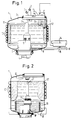
- a storage container 1 is suitable and intended for use in devices for the preparation of soft drinks by admixing an appropriate concentrate to carbonated water or possibly also to normal water.
- Fresh water is supplied to the reservoir via a supply line 2 and CO2 gas is supplied via a supply line 3.
- Sufficiently carbonated and chilled water is removed in portions via an outlet line 4 in order to prepare a soft drink.
- the sufficient carbonation is at least supported by a circulation pump 5, which sucks the CO2 gas located there from the head region 6 of the storage container 1 via an intake pipe 7 and mixes it into the stored water 8 at the level of the circulation pump 5. This CO2 gas is largely dissolved in the water 8.
- the circulation pump 5 is driven by an electric motor 9.
- the cooling of the water supply takes place via evaporator coils 10 of a cooling system, not shown, in such a way that an ice jacket 11 builds up in the interior of the storage container 1 in the region of the evaporator coils 10, which rest on the wall of the storage container 1 with good thermal conductivity.
- the thickness of this ice jacket 11 is monitored by an ice sensor 12, from which the refrigeration cycle and thus the cooling capacity is controlled.
- this ice jacket 11 has the effect that, without very sensitive detection and evaluation measures, the supply of water 8 is cooled to a very constant temperature in the immediate vicinity of the freezing point, and the temperature is also essentially maintained when water changes take place, ie when carbonized Water is removed via the outlet line 4 and - controlled by a water level sensor 13 - warmer water is supplied via the feed line 2 for this purpose.
- the ice jacket degrades relatively quickly around sub-areas, which then be built up again by cooling power supplied via the evaporator lines 10.
- a known measure is to prevent icing of the outlet opening by arranging it in the vicinity and / or below the circulating pump, the heating, in particular of the drive motor 9, having a positive effect against icing.
- this measure cannot be sufficient against floating ice particles.
- the electric motor 9 is driven intermittently.
- An operating phase of approx. 1 to 2 minutes is followed by a rest phase of approx. 10 to 20 times the length.
- the circulated water 8 calms down and ice particles and ice particles floating in this water, because of their lower density, endeavor to reach the area of the surface of the water in order to unite there and / or in the edge areas to put on the ice jacket 10.
- these hazard elements are thus neutralized.
- the electric motor 9 is actuated each time carbonized water is added or fresh water is added, and the circulation pump 5 is put into operation for these time periods including a follow-up time, after which the switch-on-switch-off cycle starts again as originally.
- the circuitry measures are arbitrarily simple and can be implemented, for example, in that a signal is derived from the water level sensor 13, which sets a counting chain into an initial situation during a water inflow, which causes the power supply switch 15 to the electric motor 9 to be closed. If the water level sensor 13 detects that enough water has been refilled, the water supply via the feed line 2 is blocked and the counting chain 14 begins to run off. For a time range of 1 to 2 minutes, depending on the design of the counting chain, the switch 15 remains closed, after which it is opened until the counting chain has reached the upper setting value, after which it can be switched back to the initial situation and run through again.
- FIG. 2 shows a modification of a storage container according to FIG. 1, wherein the storage container 1 'only has evaporator coils 10' applied to it in the upper wall area is so that the ice sheet is also preferably formed in the upper region of the storage container 1 '.
- the circulation pump 5 'and its drive motor 9' run coils 16 through which other water to be cooled is passed through the carbonized water. Due to the resting phases of the circulation pump, the somewhat warmer water 8 'collects in the lower zones of the storage container 1' because of its greater density, so that a risk of icing in the coils 16 is also prevented.
Landscapes
- Chemical & Material Sciences (AREA)
- Chemical Kinetics & Catalysis (AREA)
- Physics & Mathematics (AREA)
- Thermal Sciences (AREA)
- Devices For Dispensing Beverages (AREA)
- Devices That Are Associated With Refrigeration Equipment (AREA)
- Devices For Medical Bathing And Washing (AREA)
- Carbon And Carbon Compounds (AREA)
- Water Treatment By Sorption (AREA)
Claims (5)
- Dispositif pour enrichir de l'eau avec du gaz CO₂ pour la production d'une eau carbonatée dans un réservoir (1), qui comporte, pour le refroidissement de son contenu et la formation d'une enveloppe de glace (11), au niveau de sa paroi, des canalisations de refroidissement (10) d'un circuit de refroidissement, et à l'intérieur duquel est disposée une pompe de circulation (5), au moyen de laquelle du gaz CO₂ provenant de la partie de tête (6) du réservoir est mélangé à l'eau et/ou l'eau à l'intérieur du réservoir est entrainée en rotation et/ou en circulation, et dans lequel aussi bien l'eau que le gaz CO₂ sont envoyés dans la partie de tête, et à partir de la zone du fond duquel peut être prélevée de l'eau carbonatée, caractérisé en ce qu'il est prévu un circuit de commande temporelle et que la pompe de circulation peut être mise en marche et arrêtée d'une manière commandée par le circuit de commande temporelle, dans des cycles continus.
- Utilisation du dispositif selon la revendication 1, caractérisée en ce que la pompe de circulation est mise en marche et arrêtée d'une manière commandée par le circuit de commande temporelle, dans des cycles continus.
- Utilisation selon la revendication 2, caractérisée en ce que la durée de marche de la pompe de circulation est égale à environ 1 à 2 mn et que la rapport de la durée de marche à là durée d'arrêt est compris entre environ 1:10 et 1:20.
- Utilisation selon l'une des revendications 2 ou 3, caractérisée en ce que, dans le cas du prélèvement d'eau carbonatée à partir du réservoir ou lors d'une introduction complémentaire d'eau fraîche dans le réservoir, la pompe de circulation est mise en marche pendant cette phase, y compris une phase de marche complémentaire.
- Utilisation selon la revendication 4, caractérisée en ce que cette phase de marche complémentaire dure d'environ 2 à 4 mn.
Applications Claiming Priority (3)
| Application Number | Priority Date | Filing Date | Title |
|---|---|---|---|
| DE4228771A DE4228771A1 (de) | 1992-08-28 | 1992-08-28 | Vorrichtung zum Anreichern von Wasser mit CO¶2¶-Gas zur Erzeugung von karbonisiertem Wasser |
| DE4228771 | 1992-08-28 | ||
| PCT/EP1993/002282 WO1994005409A1 (fr) | 1992-08-28 | 1993-08-25 | Dispositif pour enrichir de l'eau en gaz carbonique pour produire de l'eau gazeifiee |
Publications (2)
| Publication Number | Publication Date |
|---|---|
| EP0610483A1 EP0610483A1 (fr) | 1994-08-17 |
| EP0610483B1 true EP0610483B1 (fr) | 1996-05-15 |
Family
ID=6466710
Family Applications (1)
| Application Number | Title | Priority Date | Filing Date |
|---|---|---|---|
| EP93919164A Expired - Lifetime EP0610483B1 (fr) | 1992-08-28 | 1993-08-25 | Dispositif pour enrichir de l'eau en gaz carbonique pour produire de l'eau gazeifiee et utilisation du dispositif |
Country Status (10)
| Country | Link |
|---|---|
| US (1) | US5443763A (fr) |
| EP (1) | EP0610483B1 (fr) |
| JP (1) | JP3187053B2 (fr) |
| AT (1) | ATE137991T1 (fr) |
| AU (1) | AU4952993A (fr) |
| CA (1) | CA2122053C (fr) |
| DE (2) | DE4228771A1 (fr) |
| DK (1) | DK0610483T3 (fr) |
| WO (1) | WO1994005409A1 (fr) |
| ZA (1) | ZA936289B (fr) |
Families Citing this family (15)
| Publication number | Priority date | Publication date | Assignee | Title |
|---|---|---|---|---|
| US6427984B1 (en) | 2000-08-11 | 2002-08-06 | Hamilton Beach/Proctor-Silex, Inc. | Evaporative humidifier |
| US6576276B1 (en) | 2000-10-25 | 2003-06-10 | The Coca-Cola Company | CO2-hydrate product and method of manufacture thereof |
| US6574981B2 (en) * | 2001-09-24 | 2003-06-10 | Lancer Partnership, Ltd. | Beverage dispensing with cold carbonation |
| US6662573B2 (en) * | 2002-04-30 | 2003-12-16 | Lancer Partnership, Ltd. | Cooling bank control assembly for a beverage dispensing system |
| US20070221286A1 (en) * | 2006-03-22 | 2007-09-27 | Vinit Chantalat | Apparatus and method for producing water-filled tire |
| US8567767B2 (en) | 2010-05-03 | 2013-10-29 | Apiqe Inc | Apparatuses, systems and methods for efficient solubilization of carbon dioxide in water using high energy impact |
| MX343412B (es) * | 2010-09-24 | 2016-11-04 | Manitowoc Foodservice Companies LLC | Sistema y metodo para obtener ahorros de energia en sistema remoto de bebidas. |
| US20140079856A1 (en) | 2012-06-29 | 2014-03-20 | Darren Hatherell | Beverage Carbonating System and Method for Carbonating a Beverage |
| US9150400B2 (en) | 2013-03-15 | 2015-10-06 | Whirlpool Corporation | Beverage system icemaker and ice and water reservoir |
| EP3021686A4 (fr) * | 2013-07-18 | 2017-02-08 | SodaStream Industries Ltd. | Dispositif de distribution d'eau gazeuse |
| US9272892B2 (en) | 2013-07-29 | 2016-03-01 | Whirpool Corporation | Enhanced heat transfer to water |
| KR101876367B1 (ko) | 2013-09-05 | 2018-07-10 | 삼성전자주식회사 | 냉장고 |
| BR102014018459B1 (pt) * | 2014-07-28 | 2022-02-01 | Whirlpool S.A. | Torre de carbonatação para aparelhos dispensadores de bebidas |
| US11529594B2 (en) | 2018-11-15 | 2022-12-20 | Bonne O Inc. | Beverage carbonation system and beverage carbonator |
| US20230132444A1 (en) * | 2020-03-30 | 2023-05-04 | Societe Des Produits Nestle S.A. | Beverage preparation device |
Family Cites Families (7)
| Publication number | Priority date | Publication date | Assignee | Title |
|---|---|---|---|---|
| US2591440A (en) * | 1945-12-08 | 1952-04-01 | Kollsman Paul | Carbonating apparatus |
| US2586499A (en) * | 1947-08-16 | 1952-02-19 | Anderson & Wagner Inc | Carbonating apparatus |
| US3225965A (en) * | 1961-10-05 | 1965-12-28 | Product R & D Inc | Apparatus for dispensing beverages |
| US3412741A (en) * | 1966-04-11 | 1968-11-26 | New Water Co Inc | Method and apparatus for treating liquids with gas |
| US4123176A (en) * | 1977-10-21 | 1978-10-31 | Barker Raymond H | Photographic developer turning system |
| US5184942A (en) * | 1990-08-16 | 1993-02-09 | The Coca Cola Company | Storage container with an electrically operable circulating pump |
| US5190189A (en) * | 1990-10-30 | 1993-03-02 | Imi Cornelius Inc. | Low height beverage dispensing apparatus |
-
1992
- 1992-08-28 DE DE4228771A patent/DE4228771A1/de not_active Withdrawn
-
1993
- 1993-08-25 EP EP93919164A patent/EP0610483B1/fr not_active Expired - Lifetime
- 1993-08-25 DK DK93919164.9T patent/DK0610483T3/da active
- 1993-08-25 WO PCT/EP1993/002282 patent/WO1994005409A1/fr not_active Ceased
- 1993-08-25 AU AU49529/93A patent/AU4952993A/en not_active Abandoned
- 1993-08-25 DE DE59302605T patent/DE59302605D1/de not_active Expired - Fee Related
- 1993-08-25 CA CA002122053A patent/CA2122053C/fr not_active Expired - Fee Related
- 1993-08-25 JP JP50682894A patent/JP3187053B2/ja not_active Expired - Fee Related
- 1993-08-25 AT AT93919164T patent/ATE137991T1/de not_active IP Right Cessation
- 1993-08-27 ZA ZA936289A patent/ZA936289B/xx unknown
-
1994
- 1994-04-28 US US08/233,971 patent/US5443763A/en not_active Expired - Lifetime
Also Published As
| Publication number | Publication date |
|---|---|
| DK0610483T3 (da) | 1996-10-07 |
| EP0610483A1 (fr) | 1994-08-17 |
| WO1994005409A1 (fr) | 1994-03-17 |
| CA2122053C (fr) | 1997-01-07 |
| JP3187053B2 (ja) | 2001-07-11 |
| US5443763A (en) | 1995-08-22 |
| JPH07503183A (ja) | 1995-04-06 |
| DE59302605D1 (de) | 1996-06-20 |
| DE4228771A1 (de) | 1994-03-03 |
| CA2122053A1 (fr) | 1994-03-17 |
| ZA936289B (en) | 1994-04-05 |
| ATE137991T1 (de) | 1996-06-15 |
| AU4952993A (en) | 1994-03-29 |
Similar Documents
| Publication | Publication Date | Title |
|---|---|---|
| EP0610483B1 (fr) | Dispositif pour enrichir de l'eau en gaz carbonique pour produire de l'eau gazeifiee et utilisation du dispositif | |
| EP0610482B1 (fr) | Dispositif pour preparer et distribuer des boissons rafraichissantes | |
| DE3876929T2 (de) | Vorrichtung zum ausschenken alkoholfreier getraenke. | |
| EP0802155B1 (fr) | Procédé et dispositif de et carbonatation d'eau potable | |
| DE102008012486B4 (de) | Imprägnierverfahren und Schankanlage mit Imprägniervorrichtung | |
| DE60031984T2 (de) | Getränkeabgabevorrichtung mit verbesserter kühlkammervorrichtung | |
| WO1994005591A1 (fr) | Dispositif pour preparer et distribuer des boissons rafraichissantes | |
| DE60033537T2 (de) | Abgabegerät für gefrorene kohlensäurehaltige getränke | |
| DE2359033C3 (de) | Vorrichtung zum Bereiten und Ausgeben von CO↓2↓-haltigen Getränken | |
| DE3522702A1 (de) | Behandlung von fluessigkeiten | |
| CH625402A5 (en) | Method and device for producing and dispensing carbonated liquids | |
| EP0609423B1 (fr) | Procede pour enrichir de l'eau en gaz carbonique afin de produire de l'eau gazeifiee | |
| DE3707779A1 (de) | Vorrichtung zum herstellen von speiseeis, milchshake oder gefrorenen suessspeisen aus einem fliessfaehigen ansatz | |
| EP1776178A1 (fr) | Procede et dispositif de carbonisation d'un liquide, de preference d'eau du robinet | |
| EP0610485B1 (fr) | Dispositif pour l'enrichissement d'eau en gaz carbonique pour la production d'eau gazeifiee | |
| DE4228772A1 (de) | Vorrichtung zum Anreichern von Wasser mit CO¶2¶-Gas zur Erzeugung von karbonisiertem Wasser | |
| DE69920939T2 (de) | Getränke-abgabevorrichtung mit verbesserter kühlungsleistung | |
| DE3024590C2 (fr) | ||
| DE3417004A1 (de) | Ausschank fuer postmixgetraenke | |
| WO1994005407A1 (fr) | Procede et dispositif pour preparer et distribuer des boissons rafraichissantes | |
| DE4228777A1 (de) | Vorrichtung zum Erzeugen und Bereitstellen von karbonisiertem Wasser in einem Vorratsbehälter | |
| DE69301355T2 (de) | Vorrichtung zum automatischen herstellen von halbflüssigen nahrungsmitteln und dabei verwendete reinigungsgerät | |
| DE8414000U1 (de) | Ausgabegerät für Postmixgetränke | |
| DE3213580C2 (de) | Getränkebereiter mit Kühlung eines Getränkekonzentratvorratsbehälters durch das im Karbonisator umgewälzte Trinkwasser | |
| DE3430952A1 (de) | Anordnung einer umwaelzpumpe in einem vorratsbehaelter |
Legal Events
| Date | Code | Title | Description |
|---|---|---|---|
| PUAI | Public reference made under article 153(3) epc to a published international application that has entered the european phase |
Free format text: ORIGINAL CODE: 0009012 |
|
| 17P | Request for examination filed |
Effective date: 19940322 |
|
| AK | Designated contracting states |
Kind code of ref document: A1 Designated state(s): AT CH DE DK ES FR GB IT LI NL SE |
|
| 17Q | First examination report despatched |
Effective date: 19950626 |
|
| GRAH | Despatch of communication of intention to grant a patent |
Free format text: ORIGINAL CODE: EPIDOS IGRA |
|
| GRAA | (expected) grant |
Free format text: ORIGINAL CODE: 0009210 |
|
| AK | Designated contracting states |
Kind code of ref document: B1 Designated state(s): AT CH DE DK ES FR GB IT LI NL SE |
|
| PG25 | Lapsed in a contracting state [announced via postgrant information from national office to epo] |
Ref country code: FR Effective date: 19960515 Ref country code: ES Free format text: THE PATENT HAS BEEN ANNULLED BY A DECISION OF A NATIONAL AUTHORITY Effective date: 19960515 |
|
| REF | Corresponds to: |
Ref document number: 137991 Country of ref document: AT Date of ref document: 19960615 Kind code of ref document: T |
|
| REF | Corresponds to: |
Ref document number: 59302605 Country of ref document: DE Date of ref document: 19960620 |
|
| ITF | It: translation for a ep patent filed | ||
| PG25 | Lapsed in a contracting state [announced via postgrant information from national office to epo] |
Ref country code: SE Effective date: 19960815 |
|
| PGFP | Annual fee paid to national office [announced via postgrant information from national office to epo] |
Ref country code: DK Payment date: 19960815 Year of fee payment: 4 |
|
| REG | Reference to a national code |
Ref country code: DK Ref legal event code: T3 |
|
| EN | Fr: translation not filed | ||
| GBT | Gb: translation of ep patent filed (gb section 77(6)(a)/1977) |
Effective date: 19960919 |
|
| REG | Reference to a national code |
Ref country code: CH Ref legal event code: NV Representative=s name: RITSCHER & SEIFERT PATENTANWAELTE VSP |
|
| PLBE | No opposition filed within time limit |
Free format text: ORIGINAL CODE: 0009261 |
|
| STAA | Information on the status of an ep patent application or granted ep patent |
Free format text: STATUS: NO OPPOSITION FILED WITHIN TIME LIMIT |
|
| 26N | No opposition filed | ||
| PG25 | Lapsed in a contracting state [announced via postgrant information from national office to epo] |
Ref country code: DK Free format text: LAPSE BECAUSE OF NON-PAYMENT OF DUE FEES Effective date: 19970825 |
|
| REG | Reference to a national code |
Ref country code: DK Ref legal event code: EBP |
|
| REG | Reference to a national code |
Ref country code: GB Ref legal event code: IF02 |
|
| PGFP | Annual fee paid to national office [announced via postgrant information from national office to epo] |
Ref country code: CH Payment date: 20020717 Year of fee payment: 10 |
|
| PGFP | Annual fee paid to national office [announced via postgrant information from national office to epo] |
Ref country code: NL Payment date: 20020725 Year of fee payment: 10 |
|
| PG25 | Lapsed in a contracting state [announced via postgrant information from national office to epo] |
Ref country code: LI Free format text: LAPSE BECAUSE OF NON-PAYMENT OF DUE FEES Effective date: 20030831 Ref country code: CH Free format text: LAPSE BECAUSE OF NON-PAYMENT OF DUE FEES Effective date: 20030831 |
|
| PG25 | Lapsed in a contracting state [announced via postgrant information from national office to epo] |
Ref country code: NL Free format text: LAPSE BECAUSE OF NON-PAYMENT OF DUE FEES Effective date: 20040301 |
|
| REG | Reference to a national code |
Ref country code: CH Ref legal event code: PL |
|
| NLV4 | Nl: lapsed or anulled due to non-payment of the annual fee |
Effective date: 20040301 |
|
| PGFP | Annual fee paid to national office [announced via postgrant information from national office to epo] |
Ref country code: DE Payment date: 20040805 Year of fee payment: 12 |
|
| PGFP | Annual fee paid to national office [announced via postgrant information from national office to epo] |
Ref country code: GB Payment date: 20050816 Year of fee payment: 13 Ref country code: AT Payment date: 20050816 Year of fee payment: 13 |
|
| PG25 | Lapsed in a contracting state [announced via postgrant information from national office to epo] |
Ref country code: IT Free format text: LAPSE BECAUSE OF NON-PAYMENT OF DUE FEES Effective date: 20050825 |
|
| PG25 | Lapsed in a contracting state [announced via postgrant information from national office to epo] |
Ref country code: DE Free format text: LAPSE BECAUSE OF NON-PAYMENT OF DUE FEES Effective date: 20060301 |
|
| PG25 | Lapsed in a contracting state [announced via postgrant information from national office to epo] |
Ref country code: AT Free format text: LAPSE BECAUSE OF NON-PAYMENT OF DUE FEES Effective date: 20060825 |
|
| GBPC | Gb: european patent ceased through non-payment of renewal fee |
Effective date: 20060825 |
|
| PG25 | Lapsed in a contracting state [announced via postgrant information from national office to epo] |
Ref country code: GB Free format text: LAPSE BECAUSE OF NON-PAYMENT OF DUE FEES Effective date: 20060825 |