EP0610541B1 - Bausatz - Google Patents
Bausatz Download PDFInfo
- Publication number
- EP0610541B1 EP0610541B1 EP93105114A EP93105114A EP0610541B1 EP 0610541 B1 EP0610541 B1 EP 0610541B1 EP 93105114 A EP93105114 A EP 93105114A EP 93105114 A EP93105114 A EP 93105114A EP 0610541 B1 EP0610541 B1 EP 0610541B1
- Authority
- EP
- European Patent Office
- Prior art keywords
- set according
- building set
- bodies
- connecting bars
- bores
- Prior art date
- Legal status (The legal status is an assumption and is not a legal conclusion. Google has not performed a legal analysis and makes no representation as to the accuracy of the status listed.)
- Expired - Lifetime
Links
Images



Classifications
-
- A—HUMAN NECESSITIES
- A63—SPORTS; GAMES; AMUSEMENTS
- A63H—TOYS, e.g. TOPS, DOLLS, HOOPS OR BUILDING BLOCKS
- A63H33/00—Other toys
- A63H33/04—Building blocks, strips, or similar building parts
- A63H33/10—Building blocks, strips, or similar building parts to be assembled by means of additional non-adhesive elements
-
- A—HUMAN NECESSITIES
- A63—SPORTS; GAMES; AMUSEMENTS
- A63H—TOYS, e.g. TOPS, DOLLS, HOOPS OR BUILDING BLOCKS
- A63H33/00—Other toys
- A63H33/04—Building blocks, strips, or similar building parts
Definitions
- the invention relates to a kit for building spatial structures. Furthermore, the invention relates to special uses of this kit, as well as the individual basic elements from which the kit is constructed. Finally, the invention relates to a spatial structure that is constructed with this kit.
- Game kits are already known for building smaller spatial structures.
- Such play kits essentially comprise two basic elements, namely bodies with bores on the one hand and connecting rods on the other hand, by means of which these bodies can be connected to one another (see FR-A-2 384 519).
- the connecting rods can be inserted into the holes in the body by clamping. You generally have to hammer them in and special pliers are required to remove them. Subsequent installation of a body between two bodies of an existing spatial structure is practically impossible, since for this purpose the two bodies of the existing spatial structure would have to be spread apart in order to be able to use connecting rods between them for the new body to be inserted.
- the known toy kits are not suitable for building larger structures, such as shelves, stands, scaffolding or walk-in children's houses, children's cars or children's cranes with typical dimensions of one meter and above.
- the primary object of the invention is to create a novel, easy-to-use kit with which stable spatial structures can be constructed in a wide variety of variations.
- the bodies Via the connecting rods, which are inserted into the holes in the body, the bodies can first be fixed relative to one another to such an extent that they can only be moved along the connecting rod.
- the additional third basic element according to the invention namely the spacer sleeves that can be pushed onto the connecting rods
- the distance between two adjacent bodies on the connecting rod can be determined in a simple manner by the connecting rod resting on the left and right of the respective body.
- the construction of a spatial structure is very simple: you push a connecting rod into or through a first body, then slide a spacer sleeve onto the relevant connecting rod and then push the next body onto the connecting rod. The spacer sleeve, against which the two bodies rest, then automatically defines the distance between the two bodies along the connecting rod in a well-defined manner.
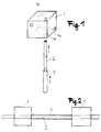
- Fig. 1 the three basic elements of the kit according to the invention are described, namely a body 1, which is penetrated by bores 1a, a connecting rod 2 which can be pushed into the bores or through the bores 1a and, as a third element, a spacer sleeve 3 which can be pushed onto the connecting rod 2 to a further body 1, not shown in FIG. 1.
- the body is a cube which is penetrated by three mutually perpendicular bores. Because the holes in the body run past each other (i.e. do not intersect), you can continue building from body 1 in all three spatial directions.
- the connecting rods 2 preferably fit exactly into the bores 1a of the body 1 with little play and are initially loosely displaceable and rotatable therein. This allows the connecting rods 2 (also for children) to be easily inserted around the bores 1a of the body.
- the spacer sleeves 3 are also conveniently displaceable loosely with respect to the connecting rods 2 in order to allow them to be easily pushed on.
- cylindrical connecting rods 2, on which hollow cylindrical spacer sleeves 3 are pushed are the cheapest.
- wood in particular is a suitable material, while the spacer sleeves 3 are advantageously made of plastic. In principle, however, it is also conceivable to adapt the material of the three basic elements of the kit according to the invention to the existing requirements. Other materials such as metal (for example for building shelves) can also be used.
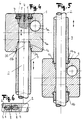
- FIG. 2 shows part of a spatial structure that is constructed by the kit according to the invention.
- the two bodies 1 are connected to one another by a connecting rod 2 which, in the rest, can run continuously to further bodies (not shown in more detail).
- a spacer sleeve 3 is pushed onto the connecting rods 2.
- FIG. 3 shows different embodiments of bodies 1 of the kit according to the invention.
- these are advantageously of convex design, as is shown in FIG. 3.
- the spherical ones shown there are particularly suitable and cuboid or cube-shaped body.
- prism-shaped bodies and bodies of other shapes are also suitable in principle as bodies for the kit according to the invention.
- the two uppermost bodies shown in FIG. 3 each have three mutually perpendicular bores 1a which pass through the respective body 1.
- Such bodies can be used as basic elements in a universal kit and allow assembly in all three spatial directions.
- the plate-shaped body shown below is particularly suitable for the construction of shelves, tables, chair surfaces and other flat structures.
- the prism-shaped body 1 shown at the bottom left in FIG. 3 is suitable for connecting inclined elements such as the roof of a children's home.
- a cube-shaped body is shown at the bottom right in FIG. 3, which has four parallel bores in each of the three spatial directions, but which do not intersect in the interior of the cube-shaped body.
- Such a body offers further possible variations in construction, in particular the use of parallel connecting rods with pushed-on spacer sleeves in order to achieve a higher stability of the connection between two adjacent bodies.
- Body shapes other than those shown in FIG. 3 are of course also conceivable and possible.
- the connecting rods 2 can be easily inserted into the openings 1 a of the body 1 in order to enable a simple, rapid construction.
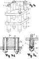
- the connecting rod In order to increase the stability of the built-up spatial structure, there is fundamentally the possibility of slightly boring the body 1 a to make it narrower so that the connecting rod is clamped in it. However, this also makes it difficult to insert the connecting rod. Therefore, it is advantageous if separate means for inhibiting or preventing displacement or twisting of the connecting rod in the body 1 are arranged, which allow the connecting rod 2 to be inserted relatively easily into the body 1, but nevertheless improve the hold of the connecting rod 2 in the body 1. An exemplary embodiment of this is shown in FIG. 4.
- the connecting rod 2 shown there has a slot-shaped recess 4 at the end region, which allows the end region of the connecting rod 2 to be compressed radially.
- the connecting rod has at the end region a circumferential groove 5 into which an annular holding element 6 can penetrate, which on the other hand also bears against the body 1 in a circumferential groove 7.
- This holding element 7 inhibits the axial movement of the connecting rod 2 in the body 1, but nevertheless allows the connecting rod 2 to be pushed in or pulled out by the end region of the connecting rod being able to yield radially due to the longitudinal slot 4.
- the retaining ring 6 is not absolutely necessary for the functioning of the kit according to the invention.
- the stability of the spatial structures is sufficient even without such retaining rings 6, especially for playing purposes.
- Even with higher stability requirements such as, for example, shelves, the retaining ring 6 or a functionally equivalent means need not be provided for all the bodies 1 threaded onto a connecting rod 2. Rather, it is sufficient if this is done on the bodies 1 which are arranged at the end of a connecting rod.
- the spacer sleeves 3 can be provided that the spacer sleeves 3 penetrate a little into the bore 1a of the body 1 and are held there by clamping, as shown in FIG. 2.
- the bores 1a of the body 1 each have an enlarged area 1b at the end into which the connecting rods 2 can be inserted by clamping.
- the enlarged area 1b has a section 1c which is flared outwards.
- the spacer sleeves 3 In order to reach the conical region 1c of the bores 1a, at least some of the spacer sleeves 3 have a conically tapered end 3a.
- a spacer sleeve 3 can have two diametrically opposed longitudinal cuts 3b at the end, which enable the end of the spacer sleeves 3 to be compressed radially and thus enable a firm clamping fit in the body 1.
- the clamping fit of the spacer sleeves 3 in the body 1 is advantageous for some embodiments but is fundamentally not necessary.
- the spacer sleeves 3 can be inserted into the body 1 relatively loosely or only very slightly by clamping, as is shown in FIG. 5.
- the bodies 1 can look the same as in FIG. 4.
- the non-conical spacer sleeves 3 of FIG. 5 simply do not use the conical section of the bores in the bodies 1.
- the circumferential groove 7 in the body 1 at the there continuous connecting rod 2 is not required, but is generally available if necessary (see FIG. 4).
- connecting rods can be pieced together according to a preferred embodiment of the invention.
- An example of this is shown in FIG. 6.
- FIG. 7a, 7b and 7c show a shelf constructed by means of a kit according to the invention.
- This shelf consists of two plate-shaped bodies 1, each with four holes, through which four connecting rods 2 are passed. Spacers 3 are pushed onto the connecting rods 2 according to the invention.
- the shelf shown can be assembled easily and quickly with high stability.
- a preferred embodiment of the spacer sleeves 3 is that they have grooves 3c running in the axial direction, into which plates 11 can be inserted axially if necessary.
- Fig. 7b shows a plate 11 axially inserted in this way in section.
- FIG. 8 shows the construction of a walk-in children's house by means of a kit according to the invention.
- FIG. 9 shows a child's car built from a kit according to the invention, with which children can actually drive.
- the connecting rods and spacers 2, 3 are only shown schematically.
- the wheels 12 can be rotatably mounted on connecting rods which extend beyond the bodies 1, a groove 5 in the connecting rods 2 being able to prevent the wheels from falling if, as shown for example in FIG. 12, a projection 13 penetrating into the groove exhibit.
- the seat and the back of the chair can consist of simple plates 14 or the like, for example, via a plug connection. are connected to the bodies 1 of the kit.
- the kit according to the invention can also be used to mount rotatable parts on the bodies 1, for example an impeller 12, a gear 15 or a pulley 16.
- kit according to the invention essentially the same basic elements can be used to build up the most diverse spatial structures.
- the connecting rods and / or the spacer sleeves are available in different lengths.
- bodies for example spherical bodies and cube-shaped bodies, mixed in a kit.
- the kit according to the invention is suitable as a toy, since it is easy to assemble and disassemble and, with simple, straightforward basic elements, allows numerous variation options for children.
- the kit system according to the invention is also suitable for utility applications, for example for assembling shelves, stands, scaffolding or the like.
- the body connecting rods or spacer sleeves of the kit according to the invention can in principle also be sold individually, which is why the invention also relates to these individual basic elements.
- the invention also relates to a spatial structure which is constructed using a kit according to the invention.
Landscapes
- Toys (AREA)
- Reinforcement Elements For Buildings (AREA)
- Fencing (AREA)
- Conveying And Assembling Of Building Elements In Situ (AREA)
- Heterocyclic Carbon Compounds Containing A Hetero Ring Having Oxygen Or Sulfur (AREA)
- Polysaccharides And Polysaccharide Derivatives (AREA)
- Glass Compositions (AREA)
- Biological Treatment Of Waste Water (AREA)
- Medicines Containing Plant Substances (AREA)
- Investigating, Analyzing Materials By Fluorescence Or Luminescence (AREA)
- Devices For Use In Laboratory Experiments (AREA)
Priority Applications (6)
| Application Number | Priority Date | Filing Date | Title |
|---|---|---|---|
| AT93105114T ATE110290T1 (de) | 1993-03-29 | 1993-03-29 | Bausatz. |
| ES93105114T ES2059219T3 (es) | 1993-03-29 | 1993-03-29 | Juego de piezas de construccion. |
| DE59300008T DE59300008D1 (de) | 1993-03-29 | 1993-03-29 | Bausatz. |
| DK93105114.8T DK0610541T3 (da) | 1993-03-29 | 1993-03-29 | Byggesæt |
| EP93105114A EP0610541B1 (de) | 1993-03-29 | 1993-03-29 | Bausatz |
| CA002119605A CA2119605A1 (en) | 1993-03-29 | 1994-03-22 | Building set |
Applications Claiming Priority (1)
| Application Number | Priority Date | Filing Date | Title |
|---|---|---|---|
| EP93105114A EP0610541B1 (de) | 1993-03-29 | 1993-03-29 | Bausatz |
Publications (2)
| Publication Number | Publication Date |
|---|---|
| EP0610541A1 EP0610541A1 (de) | 1994-08-17 |
| EP0610541B1 true EP0610541B1 (de) | 1994-08-24 |
Family
ID=8212752
Family Applications (1)
| Application Number | Title | Priority Date | Filing Date |
|---|---|---|---|
| EP93105114A Expired - Lifetime EP0610541B1 (de) | 1993-03-29 | 1993-03-29 | Bausatz |
Country Status (6)
| Country | Link |
|---|---|
| EP (1) | EP0610541B1 (da) |
| AT (1) | ATE110290T1 (da) |
| CA (1) | CA2119605A1 (da) |
| DE (1) | DE59300008D1 (da) |
| DK (1) | DK0610541T3 (da) |
| ES (1) | ES2059219T3 (da) |
Family Cites Families (3)
| Publication number | Priority date | Publication date | Assignee | Title |
|---|---|---|---|---|
| DE311277C (da) * | ||||
| SE400901B (sv) * | 1977-03-24 | 1978-04-17 | Intermatch Sa | Modulsystem for forstroelse- och/eller pedagogiska lekar |
| DE8515260U1 (de) * | 1985-05-21 | 1986-09-18 | Bogenschütz, Peter, 1000 Berlin | Zusammenbaubares und zerlegbares Spielzeug vorzugsweise für Kinder |
-
1993
- 1993-03-29 AT AT93105114T patent/ATE110290T1/de active
- 1993-03-29 EP EP93105114A patent/EP0610541B1/de not_active Expired - Lifetime
- 1993-03-29 DK DK93105114.8T patent/DK0610541T3/da active
- 1993-03-29 DE DE59300008T patent/DE59300008D1/de not_active Expired - Fee Related
- 1993-03-29 ES ES93105114T patent/ES2059219T3/es not_active Expired - Lifetime
-
1994
- 1994-03-22 CA CA002119605A patent/CA2119605A1/en not_active Abandoned
Also Published As
| Publication number | Publication date |
|---|---|
| EP0610541A1 (de) | 1994-08-17 |
| ES2059219T3 (es) | 1994-11-01 |
| CA2119605A1 (en) | 1994-09-30 |
| DE59300008D1 (de) | 1994-10-27 |
| ATE110290T1 (de) | 1994-09-15 |
| DK0610541T3 (da) | 1995-01-30 |
Similar Documents
| Publication | Publication Date | Title |
|---|---|---|
| DE3342616A1 (de) | Profilrohr fuer die herstellung von leicht montier- und wieder demontierbaren aufbauten | |
| DE1478447B1 (de) | Baukastenspiel | |
| DE2520510A1 (de) | Verbindungs-knotenstueck | |
| DE2152341A1 (de) | Bauspielzeug | |
| DE3620379C2 (da) | ||
| DE2457674A1 (de) | Knotenverbindung fuer aus stangenfoermigen bauelementen zusammensetzbare konstruktionen | |
| EP2392742A2 (de) | Kantenprofilelement | |
| DE3014507C2 (da) | ||
| EP0610541B1 (de) | Bausatz | |
| DE3920959C2 (da) | ||
| DE102006031417A1 (de) | Bausatz | |
| DE202006014679U1 (de) | Vorrichtung zur Bildung von Stabfachwerken | |
| DE2434365A1 (de) | Spielbausatz | |
| DE9315767U1 (de) | Variabel einsetzbares, universelles Bauelement zur Herstellung von Präsentations- und Verkaufseinrichtungen, Möbeln, räumlicher Gebilde, Innenausbauten u.dgl. | |
| DE10200298B4 (de) | Modell-Mehrzweckscheibe und Modellbau-Lagerelement | |
| DE29603402U1 (de) | Rahmenwerk mit Winkel- oder Eckverbindungen von Metallprofilen, insbesondere aus Leichtmetall | |
| DE8336732U1 (de) | Verbindungselement für Baukasten-Möbel | |
| DE2626407A1 (de) | Biegesteife steckverbindung zum verbinden von regal-, geruest-, tribuenen-, treppen- oder dergleichen bauteilen | |
| DE9200616U1 (de) | Möbeltisch | |
| DE2200822A1 (de) | Baukasten-system | |
| DE2410211A1 (de) | Kombinationsmoebel | |
| DE202016001304U1 (de) | Verbindungselement für Bauteile eines Katzenkratzbaums und Katzenkratzbaum mit einem solchen Verbindungselement | |
| DE202005016961U1 (de) | Bausatz | |
| EP1157216B1 (de) | Vorrichtung zum befestigen von gegenständen an säulen | |
| AT510934B1 (de) | Verbindungselement |
Legal Events
| Date | Code | Title | Description |
|---|---|---|---|
| PUAI | Public reference made under article 153(3) epc to a published international application that has entered the european phase |
Free format text: ORIGINAL CODE: 0009012 |
|
| GRAA | (expected) grant |
Free format text: ORIGINAL CODE: 0009210 |
|
| 17P | Request for examination filed |
Effective date: 19931002 |
|
| AK | Designated contracting states |
Kind code of ref document: A1 Designated state(s): AT BE CH DE DK ES FR GB GR IE IT LI LU NL PT SE |
|
| AK | Designated contracting states |
Kind code of ref document: B1 Designated state(s): AT BE CH DE DK ES FR GB GR IE IT LI LU NL PT SE |
|
| REF | Corresponds to: |
Ref document number: 110290 Country of ref document: AT Date of ref document: 19940915 Kind code of ref document: T |
|
| GBT | Gb: translation of ep patent filed (gb section 77(6)(a)/1977) |
Effective date: 19940826 |
|
| REF | Corresponds to: |
Ref document number: 59300008 Country of ref document: DE Date of ref document: 19941027 |
|
| REG | Reference to a national code |
Ref country code: ES Ref legal event code: FG2A Ref document number: 2059219 Country of ref document: ES Kind code of ref document: T3 |
|
| ITF | It: translation for a ep patent filed | ||
| REG | Reference to a national code |
Ref country code: IE Ref legal event code: FG4D Free format text: 61107 |
|
| ET | Fr: translation filed | ||
| REG | Reference to a national code |
Ref country code: GR Ref legal event code: FG4A Free format text: 3013753 |
|
| REG | Reference to a national code |
Ref country code: DK Ref legal event code: T3 |
|
| EAL | Se: european patent in force in sweden |
Ref document number: 93105114.8 |
|
| SC4A | Pt: translation is available |
Free format text: 940824 AVAILABILITY OF NATIONAL TRANSLATION |
|
| PG25 | Lapsed in a contracting state [announced via postgrant information from national office to epo] |
Ref country code: LU Free format text: LAPSE BECAUSE OF NON-PAYMENT OF DUE FEES Effective date: 19950331 |
|
| PG25 | Lapsed in a contracting state [announced via postgrant information from national office to epo] |
Ref country code: IE Free format text: LAPSE BECAUSE OF NON-PAYMENT OF DUE FEES Effective date: 19950419 |
|
| REG | Reference to a national code |
Ref country code: IE Ref legal event code: FD4D Ref document number: 61107 Country of ref document: IE |
|
| PLBE | No opposition filed within time limit |
Free format text: ORIGINAL CODE: 0009261 |
|
| 26N | No opposition filed | ||
| REG | Reference to a national code |
Ref country code: GB Ref legal event code: IF02 |
|
| PGFP | Annual fee paid to national office [announced via postgrant information from national office to epo] |
Ref country code: GB Payment date: 20050323 Year of fee payment: 13 |
|
| PGFP | Annual fee paid to national office [announced via postgrant information from national office to epo] |
Ref country code: FR Payment date: 20050325 Year of fee payment: 13 |
|
| PGFP | Annual fee paid to national office [announced via postgrant information from national office to epo] |
Ref country code: PT Payment date: 20050328 Year of fee payment: 13 |
|
| PGFP | Annual fee paid to national office [announced via postgrant information from national office to epo] |
Ref country code: GR Payment date: 20050329 Year of fee payment: 13 |
|
| PGFP | Annual fee paid to national office [announced via postgrant information from national office to epo] |
Ref country code: CH Payment date: 20050330 Year of fee payment: 13 |
|
| PGFP | Annual fee paid to national office [announced via postgrant information from national office to epo] |
Ref country code: SE Payment date: 20050331 Year of fee payment: 13 Ref country code: NL Payment date: 20050331 Year of fee payment: 13 Ref country code: ES Payment date: 20050331 Year of fee payment: 13 Ref country code: DK Payment date: 20050331 Year of fee payment: 13 |
|
| PGFP | Annual fee paid to national office [announced via postgrant information from national office to epo] |
Ref country code: BE Payment date: 20050414 Year of fee payment: 13 |
|
| PGFP | Annual fee paid to national office [announced via postgrant information from national office to epo] |
Ref country code: DE Payment date: 20050421 Year of fee payment: 13 |
|
| PG25 | Lapsed in a contracting state [announced via postgrant information from national office to epo] |
Ref country code: GB Free format text: LAPSE BECAUSE OF NON-PAYMENT OF DUE FEES Effective date: 20060329 |
|
| PG25 | Lapsed in a contracting state [announced via postgrant information from national office to epo] |
Ref country code: SE Free format text: LAPSE BECAUSE OF NON-PAYMENT OF DUE FEES Effective date: 20060330 Ref country code: ES Free format text: LAPSE BECAUSE OF NON-PAYMENT OF DUE FEES Effective date: 20060330 |
|
| PG25 | Lapsed in a contracting state [announced via postgrant information from national office to epo] |
Ref country code: LI Free format text: LAPSE BECAUSE OF NON-PAYMENT OF DUE FEES Effective date: 20060331 Ref country code: DK Free format text: LAPSE BECAUSE OF NON-PAYMENT OF DUE FEES Effective date: 20060331 Ref country code: CH Free format text: LAPSE BECAUSE OF NON-PAYMENT OF DUE FEES Effective date: 20060331 Ref country code: BE Free format text: LAPSE BECAUSE OF NON-PAYMENT OF DUE FEES Effective date: 20060331 |
|
| PGFP | Annual fee paid to national office [announced via postgrant information from national office to epo] |
Ref country code: IT Payment date: 20060331 Year of fee payment: 14 |
|
| PG25 | Lapsed in a contracting state [announced via postgrant information from national office to epo] |
Ref country code: PT Free format text: LAPSE BECAUSE OF NON-PAYMENT OF DUE FEES Effective date: 20060929 |
|
| PG25 | Lapsed in a contracting state [announced via postgrant information from national office to epo] |
Ref country code: NL Free format text: LAPSE BECAUSE OF NON-PAYMENT OF DUE FEES Effective date: 20061001 |
|
| PG25 | Lapsed in a contracting state [announced via postgrant information from national office to epo] |
Ref country code: DE Free format text: LAPSE BECAUSE OF NON-PAYMENT OF DUE FEES Effective date: 20061003 |
|
| REG | Reference to a national code |
Ref country code: DK Ref legal event code: EBP |
|
| REG | Reference to a national code |
Ref country code: CH Ref legal event code: PL |
|
| EUG | Se: european patent has lapsed | ||
| GBPC | Gb: european patent ceased through non-payment of renewal fee |
Effective date: 20060329 |
|
| REG | Reference to a national code |
Ref country code: PT Ref legal event code: MM4A Free format text: LAPSE DUE TO NON-PAYMENT OF FEES Effective date: 20060929 |
|
| NLV4 | Nl: lapsed or anulled due to non-payment of the annual fee |
Effective date: 20061001 |
|
| REG | Reference to a national code |
Ref country code: FR Ref legal event code: ST Effective date: 20061130 |
|
| REG | Reference to a national code |
Ref country code: ES Ref legal event code: FD2A Effective date: 20060330 |
|
| BERE | Be: lapsed |
Owner name: *SIKORA GUNTHER Effective date: 20060331 |
|
| PG25 | Lapsed in a contracting state [announced via postgrant information from national office to epo] |
Ref country code: FR Free format text: LAPSE BECAUSE OF NON-PAYMENT OF DUE FEES Effective date: 20060331 |
|
| PG25 | Lapsed in a contracting state [announced via postgrant information from national office to epo] |
Ref country code: GR Free format text: LAPSE BECAUSE OF NON-PAYMENT OF DUE FEES Effective date: 20061002 |
|
| PG25 | Lapsed in a contracting state [announced via postgrant information from national office to epo] |
Ref country code: IT Free format text: LAPSE BECAUSE OF NON-PAYMENT OF DUE FEES Effective date: 20070329 |
|
| PGFP | Annual fee paid to national office [announced via postgrant information from national office to epo] |
Ref country code: AT Payment date: 20120314 Year of fee payment: 20 |
|
| REG | Reference to a national code |
Ref country code: AT Ref legal event code: MK07 Ref document number: 110290 Country of ref document: AT Kind code of ref document: T Effective date: 20130329 |