EP0610547A1 - Casier pour le stockage d'objets - Google Patents
Casier pour le stockage d'objets Download PDFInfo
- Publication number
- EP0610547A1 EP0610547A1 EP93115968A EP93115968A EP0610547A1 EP 0610547 A1 EP0610547 A1 EP 0610547A1 EP 93115968 A EP93115968 A EP 93115968A EP 93115968 A EP93115968 A EP 93115968A EP 0610547 A1 EP0610547 A1 EP 0610547A1
- Authority
- EP
- European Patent Office
- Prior art keywords
- side wall
- wall parts
- objects
- rod
- angle
- Prior art date
- Legal status (The legal status is an assumption and is not a legal conclusion. Google has not performed a legal analysis and makes no representation as to the accuracy of the status listed.)
- Granted
Links
- 230000015572 biosynthetic process Effects 0.000 claims description 6
- 239000000969 carrier Substances 0.000 claims description 2
- 230000000149 penetrating effect Effects 0.000 claims 1
- 238000003860 storage Methods 0.000 abstract description 2
- 230000005484 gravity Effects 0.000 description 3
- 239000000463 material Substances 0.000 description 3
- 238000006748 scratching Methods 0.000 description 3
- 230000002393 scratching effect Effects 0.000 description 3
- 230000000694 effects Effects 0.000 description 2
- 230000001154 acute effect Effects 0.000 description 1
- 238000010276 construction Methods 0.000 description 1
- 238000005520 cutting process Methods 0.000 description 1
- 238000006073 displacement reaction Methods 0.000 description 1
- 238000003780 insertion Methods 0.000 description 1
- 230000037431 insertion Effects 0.000 description 1
- 238000004519 manufacturing process Methods 0.000 description 1
- 239000002184 metal Substances 0.000 description 1
- 238000000034 method Methods 0.000 description 1
- 239000006223 plastic coating Substances 0.000 description 1
- 238000004080 punching Methods 0.000 description 1
- 230000000284 resting effect Effects 0.000 description 1
- 238000001338 self-assembly Methods 0.000 description 1
Images

Classifications
-
- G—PHYSICS
- G11—INFORMATION STORAGE
- G11B—INFORMATION STORAGE BASED ON RELATIVE MOVEMENT BETWEEN RECORD CARRIER AND TRANSDUCER
- G11B33/00—Constructional parts, details or accessories not provided for in the other groups of this subclass
- G11B33/02—Cabinets; Cases; Stands; Disposition of apparatus therein or thereon
- G11B33/04—Cabinets; Cases; Stands; Disposition of apparatus therein or thereon modified to store record carriers
- G11B33/0405—Cabinets; Cases; Stands; Disposition of apparatus therein or thereon modified to store record carriers for storing discs
- G11B33/0461—Disc storage racks
- G11B33/0483—Disc storage racks for single disc boxes
-
- A—HUMAN NECESSITIES
- A47—FURNITURE; DOMESTIC ARTICLES OR APPLIANCES; COFFEE MILLS; SPICE MILLS; SUCTION CLEANERS IN GENERAL
- A47B—TABLES; DESKS; OFFICE FURNITURE; CABINETS; DRAWERS; GENERAL DETAILS OF FURNITURE
- A47B81/00—Cabinets or racks specially adapted for other particular purposes, e.g. for storing guns or skis
- A47B81/06—Furniture aspects of radio, television, gramophone, or record cabinets
- A47B81/067—Record cabinets
-
- G—PHYSICS
- G11—INFORMATION STORAGE
- G11B—INFORMATION STORAGE BASED ON RELATIVE MOVEMENT BETWEEN RECORD CARRIER AND TRANSDUCER
- G11B23/00—Record carriers not specific to the method of recording or reproducing; Accessories, e.g. containers, specially adapted for co-operation with the recording or reproducing apparatus ; Intermediate mediums; Apparatus or processes specially adapted for their manufacture
- G11B23/02—Containers; Storing means both adapted to cooperate with the recording or reproducing means
- G11B23/023—Containers for magazines or cassettes
- G11B23/0236—Containers for several cassettes
Definitions
- the invention relates to a stand for storing flat, cuboid objects, in particular sleeves for information carriers such as compact discs, music cassettes or video cassettes, with two side wall parts enclosing an angle between them, which at least serves the purpose of forming a compartment, by means of which the objects are held laterally.
- Such stands for storing objects in particular compact disks (CDs), of which only the following will be spoken for the sake of simplicity, are often constructed in the form of a tower, in which these objects are stacked horizontally in parallel one above the other.
- CDs compact disks
- a tower of this type is known from German utility model G 91 03 216 and has two vertically extending side walls with a large number of receiving openings which are arranged at an acute angle to one another. Most of the side walls are made of sheet metal, which is why the receiving openings are formed by stamping. This rather complex production process, however, causes quite sharp-edged receiving openings, as a result of which the deposited objects, for example the CD covers, are scratched. Can not the openings are produced by punching, so their introduction into the side walls is even more complex.
- the CD When the CD is put down, it only comes into engagement with the receiving openings shortly before reaching the stable end position, which makes it particularly difficult to put down, especially when the neighboring openings are already occupied.
- the storage is particularly complicated by the fact that the receiving openings also serve as lateral guides to improve a stable position, as a result of which the CDs have to be threaded into the receiving openings, which have little play, without horizontal support.
- the height of the receiving openings also has only a slight play, since, because of the outer center of gravity of the CDs, the upper edges must be arranged as close as possible to the top of the CD in order to prevent them from tipping out.
- the side wall parts capture or support the objects at least in the area of the ends of one of their diagonals by mutual, lateral contact that the object facing sides of the wall parts are arranged at an angle greater than 90 ° to one another, and that between the wall parts for compartment formation there are arranged essentially horizontally extending supports for the objects in the form of rod-shaped elements which are slightly within the range of the diagonals of the corner between the wall parts inserted objects are positioned in the direction of the apex of the angle.
- the two side wall parts positioned at an obtuse angle in particular between 100 ° and 110 °, have no receiving openings, contrary to the prior art, but only serve to fasten the rod-shaped support elements and as a lateral contact surface.
- the rod-shaped support elements which due to their smooth, edgeless shape largely prevent scratching of the CDs on top, are arranged in parallel one above the other and form the insertion openings for the CDs.
- the features according to the invention have the effect that the respective CD case is pivoted out of the horizontal by one of its base diagonals by approximately 30 ° and is pushed with its corner edge pointing downward along its other diagonal between two support elements. Shortly after it comes into contact with the lower of the two support elements, due to its gravity, it slides down automatically according to its angle of inclination between the side wall parts in the CD stand, where it touches the side edges adjacent to the downwardly inclined corner edge Sidewall parts and by simultaneously resting on the rod-shaped receiving element located below them along a roughly their pivot diagonals assumes a stable position.
- the distance between the respective attachment point and the apex of the two side wall parts is to be determined so that the center of gravity of the body to be stacked is slightly outside the triangle formed between the apex and the attachment points, which is achieved in particular by the fact that this distance on the respective side part is somewhat is smaller than the corresponding adjacent body side.
- the support elements are each arranged somewhat in the direction of the apex in the region of the pivot diagonals, a form-fitting holding of the CD sleeves in their stable position, thereby preventing the triangle mentioned from slipping through.
- the swivel angle of the CD case in the stable position is determined by the angle that the two side wall parts form with one another.
- CD sleeves can be easily removed from the CD stand by pivoting around a corner point adjacent to a fastening point on the side wall part.
- the swiveling movement can be carried out in a simple manner with only one finger by gripping the corner point protruding from the CD stand.
- the side wall parts which serve not only as a contact surface for the CD sleeves, but also as a guide surface which specifies the displacement path, can in principle proceed from the fastening points of the rod-shaped support elements on the side wall parts only over a partial area between the fastening points and the possibly intended apex of the two Side wall parts extend, which is sufficient for an arrangement and guidance of the CDs.
- the side wall parts can consist of several individual elements or be partially interrupted by hole-like openings for reasons of material savings or the attractive appearance, but at least the side of the respective side wall part facing the object to be stacked must form a flat contact surface.
- the side wall parts have bores in accordance with a hole grid running from bottom to top, which corresponds to the vertical distance between adjacent rod-shaped elements, this allows the rod-shaped support elements to be attached at different fastening positions, as a result of which objects of different heights can be deposited.
- the bores are to be made obliquely in the direction in the side wall parts in which the rods extend.
- the CD stand can also be easily inserted or retrofitted into furniture, wherein only correspondingly positioned side wall parts, bores for the fastening openings and a rope or the like are required for the support elements.
- the rod-shaped support elements consist of a material whose surface hardness is less than the surface hardness of the object to be stacked, that is to say, for example, of plastic or plastic coating, the risk of scratching the CD sleeves is counteracted even more. This effect is particularly enhanced by the fact that the number of support points is minimized compared to conventional CD stands.
- FIG. 1 shows a CD stand, in which the vertically extending side wall parts 1a and 1b enclose an angle ⁇ between them, which is preferably between 100 ° and 110 °. If the two side wall parts 1a and 1b do not touch at the apex 4, then the angle ⁇ in the then imaginary apex must still be observed.
- a rod 2 extends horizontally between the outer ends of the two side wall parts 1a and 1b, the ends 2a and 2b of which are introduced into bores 3a and 3b at fastening points 4a and 4b in the side wall parts 1a and 1b.
- the further rods lying exactly vertically under the rod 2 are arranged for shed formation.
- the bores 3a and 3b which can be formed as blind holes or continuously, are arranged in the same direction as the rod 2.
- the attachment to the side wall parts 1a and 1b is carried out using suitable fastening devices, which are not explained in detail here.
- a CD case 5 is placed on the rod 2. Since this CD case is pivoted about its diagonal from the apex angle ⁇ by an approximately 30 ° large angle ⁇ (see FIG. 4), the end faces 5a and 5b of the CD case 5 can also be seen in the top view.
- the rod 2 lies somewhat within a diagonal 6 of the CD case 5 in the direction of the apex 4, as a result of which the CD case 5 is positively held in its stable position. Since the respective distance between the fastening points 4a and 4b and the apex is smaller than the respective side of the CD case 5 which lies against the side wall parts 1a and 1b, the CD case is slipped through by that formed between 4, 4a and 4b Triangle safely prevented.
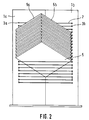
- FIG. 2 shows a front view of a CD stand with several inserted CD sleeves, in which a zigzag-shaped back and forth tensioning of a rope, for example a tennis string, is indicated by dashed lines.
- the bores 3a and 3b are expediently arranged vertically through the side wall parts. While the end 2b of the cable 2 is held in a form-fitting manner by the side wall part 1b with the aid of an end piece (not shown), the other end 2a is inserted into the hole below via a vertically downwardly extending cable piece, from where it is stretched horizontally to the side wall part 1b again . After the formation of further rod-shaped support elements, the outermost end of the rope is finally clamped to the lowermost bore of a side wall part using suitable fastening means.
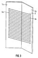
- FIG. 3 shows the CD stand from FIG. 1 without CD cases in a perspective side view.
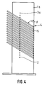
- FIG. 4 shows the CD stand from FIG. 1 with CD sleeves in a sectional view along the line I-I from FIG. 1.
- the cutting plane was placed perpendicular to the course of the rod 2, as a result of which it is also perpendicular to the base area of the CD sleeves 5.
- the CD stand can be provided with a base or cover plate in particular if, according to one embodiment of the invention, the side wall parts only extend over a partial area between the attachment points of the support elements and the then intended apex of the two side wall parts.
- the two end faces 5a and 5b of the object to be stacked are of approximately the same length, a reciprocal arrangement is also possible in which, for example, the end face 5a would rest on the side wall part 1a and the end face 5b on the side wall part 1b.
- a side wall part can also serve as a fastening and contact surface on its two sides, that is to say for two CD stands, in accordance with an exemplary embodiment that is not shown.
Landscapes
- Packaging For Recording Disks (AREA)
- Container Filling Or Packaging Operations (AREA)
- Passenger Equipment (AREA)
- Transition And Organic Metals Composition Catalysts For Addition Polymerization (AREA)
- Supports Or Holders For Household Use (AREA)
- Liquid Crystal (AREA)
- Centrifugal Separators (AREA)
- Valve-Gear Or Valve Arrangements (AREA)
- Mirrors, Picture Frames, Photograph Stands, And Related Fastening Devices (AREA)
- Pallets (AREA)
- Packaging Of Annular Or Rod-Shaped Articles, Wearing Apparel, Cassettes, Or The Like (AREA)
- Catching Or Destruction (AREA)
Applications Claiming Priority (2)
| Application Number | Priority Date | Filing Date | Title |
|---|---|---|---|
| DE4303698 | 1993-02-09 | ||
| DE4303698A DE4303698A1 (en) | 1993-02-09 | 1993-02-09 | Frame for storing CD, music and video cassettes - has side wall parts gripping stored objects at least at their diagonal ends |
Publications (2)
| Publication Number | Publication Date |
|---|---|
| EP0610547A1 true EP0610547A1 (fr) | 1994-08-17 |
| EP0610547B1 EP0610547B1 (fr) | 1998-03-04 |
Family
ID=6479958
Family Applications (1)
| Application Number | Title | Priority Date | Filing Date |
|---|---|---|---|
| EP93115968A Expired - Lifetime EP0610547B1 (fr) | 1993-02-09 | 1993-10-04 | Casier pour le stockage d'objets |
Country Status (8)
| Country | Link |
|---|---|
| US (1) | US5358124A (fr) |
| EP (1) | EP0610547B1 (fr) |
| AT (1) | ATE163794T1 (fr) |
| AU (1) | AU667598B2 (fr) |
| DE (2) | DE4303698A1 (fr) |
| DK (1) | DK0610547T3 (fr) |
| ES (1) | ES2114989T3 (fr) |
| GR (1) | GR3026466T3 (fr) |
Families Citing this family (41)
| Publication number | Priority date | Publication date | Assignee | Title |
|---|---|---|---|---|
| USD361917S (en) | 1994-01-04 | 1995-09-05 | Shahriar Dardashti | Storage rack |
| US5553720A (en) * | 1994-01-06 | 1996-09-10 | Dardashti; Shahriar | Storage and display assembly for musical media or the like |
| USD359647S (en) | 1994-01-04 | 1995-06-27 | Shahriar Dardashti | Storage rack |
| USD359648S (en) | 1994-01-21 | 1995-06-27 | Martin Hwang | Laser disc storage rack |
| US5607065A (en) * | 1995-01-04 | 1997-03-04 | Todd; Michael L. | Shelving storage unit |
| JPH09168441A (ja) * | 1995-12-21 | 1997-06-30 | Elecom Kk | ラック |
| USD387226S (en) * | 1996-02-20 | 1997-12-09 | Shahriar Dardashti | Storage and display stand |
| US5595312A (en) * | 1996-03-11 | 1997-01-21 | Dardashti; Shahriar | Easily assembled and adjustable storage and display tower assembly |
| US5908121A (en) * | 1996-03-11 | 1999-06-01 | Dardashti; Shahriar | Adjustable display assembly |
| USD384234S (en) * | 1996-03-12 | 1997-09-30 | Shahriar Dardashti | Storage assembly |
| USD403175S (en) | 1996-08-06 | 1998-12-29 | Shahriar Dardashti | Storage and display stand |
| DE19634630A1 (de) * | 1996-08-27 | 1998-03-05 | Boeder Deutschland Gmbh | Aufnahmevorrichtung für Compact-Discs (CD), Musikkassetten oder dergleichen |
| USD385726S (en) * | 1996-09-23 | 1997-11-04 | Shahriar Dardashti | Storage and display stand |
| GB2317327B (en) * | 1996-09-24 | 1998-08-05 | Kao Kuo Ming | An inclined type stackable CD rack |
| FR2754379B1 (fr) * | 1996-10-07 | 1998-12-11 | Azema Laurent | Ensemble modulable pour le rangement d'articles sensiblement plats, notamment de disques compacts |
| USD415632S (en) * | 1996-10-16 | 1999-10-26 | Shahriar Dardashti | Storage and display stand |
| USD406204S (en) * | 1997-01-21 | 1999-03-02 | Shahriar Dardashti | Storage and display stand |
| USD396985S (en) | 1997-06-27 | 1998-08-18 | Midwest Tropical, Inc. | Storage rack |
| USD407582S (en) | 1997-07-16 | 1999-04-06 | Shahriar Dardashti | Storage and display stand |
| USD406205S (en) * | 1997-07-16 | 1999-03-02 | Shahriar Dardashti | Storage and display stand |
| USD404936S (en) * | 1997-07-16 | 1999-02-02 | Shahriar Dardashti | Storage and display stand |
| AU693412B3 (en) * | 1997-09-24 | 1998-06-25 | Brant Trim | CD case storage and presentation system |
| USD403913S (en) | 1997-09-29 | 1999-01-12 | Shahriar Dardashti | Storage assembly |
| GB2336770A (en) * | 1998-04-29 | 1999-11-03 | Jackson Yu | Storage rack |
| US6050425A (en) * | 1998-07-06 | 2000-04-18 | Kantek, Inc. | Storage rack for recording media |
| US6126020A (en) * | 1999-01-06 | 2000-10-03 | Sunhing Millennium Limited | Assemblable storage and display unit |
| USD431936S (en) * | 1999-05-25 | 2000-10-17 | Lisanne Marie Moen | Shelving unit |
| USD444061S1 (en) | 1999-12-08 | 2001-06-26 | Shahriar Dardashti | Transparent display and storage box |
| USD443791S1 (en) | 2000-10-13 | 2001-06-19 | Lilliam Vernon Corporation | DVD rack |
| DE20020387U1 (de) * | 2000-12-01 | 2001-03-01 | Sunhing Millennium Ltd., Kowloon | Ablageeinrichtung für CD-Kassetten |
| US6536608B2 (en) * | 2001-07-12 | 2003-03-25 | Saint-Gobain Ceramics & Plastics, Inc. | Single cast vertical wafer boat with a Y shaped column rack |
| US6811040B2 (en) * | 2001-07-16 | 2004-11-02 | Rohm And Haas Company | Wafer holding apparatus |
| US6588604B1 (en) * | 2002-05-21 | 2003-07-08 | Chun-Hsien Tseng | Storage rack for compact discs |
| AU2003241777A1 (en) * | 2002-05-24 | 2003-12-12 | Takashi Ito | Disc stand |
| USD509983S1 (en) * | 2003-11-28 | 2005-09-27 | Kwok's Brother Manfacturing Limited | Rack for CDs, DVDs, VCDs, MDs, cassettes and the like |
| US20050236343A1 (en) * | 2004-04-26 | 2005-10-27 | Ta-Cheng Chien | Compact disk storage tower |
| HK1084828A2 (en) * | 2006-05-26 | 2006-08-04 | 凌思设计有限公司 | Multipurpose stereoscopic display shelf |
| US20090127143A1 (en) * | 2007-11-19 | 2009-05-21 | Stax Development | Interlocking Media Tray |
| DE102014000303B4 (de) * | 2014-01-10 | 2021-02-25 | Ignaz Funke | Stapelsteckgestell für gleichförmige Serien von Körperformen wie z.B. CD-, DVD- und Blu-ray - Hüllen oder dgl. |
| US10376083B1 (en) * | 2018-06-19 | 2019-08-13 | Adrian Lee | Storage rack device |
| US12515309B2 (en) * | 2023-08-02 | 2026-01-06 | A & E Incorporated | Pliers rack |
Citations (4)
| Publication number | Priority date | Publication date | Assignee | Title |
|---|---|---|---|---|
| DE732697C (de) * | 1941-09-05 | 1943-03-10 | Hans Schieren | Schallplattenstaender |
| US2825465A (en) * | 1953-10-05 | 1958-03-04 | Charles R Burgo | Phonograph record rack |
| DE8910971U1 (de) * | 1989-09-14 | 1989-12-07 | Herzig, Karl Peter | Magazin zur Aufbewahrung von Kassetten, insbesondere Compact-Disc-Kassetten |
| DE9107752U1 (de) * | 1991-06-24 | 1991-08-22 | Grimm, Karl-Heinz, 7148 Remseck | Regal zur Aufnahme von Bild- oder Tonträgern |
Family Cites Families (19)
| Publication number | Priority date | Publication date | Assignee | Title |
|---|---|---|---|---|
| US415634A (en) * | 1889-11-19 | Dish-drainer | ||
| GB200695A (en) * | 1922-07-08 | 1923-07-19 | Parker Winder & Achurch Ltd | Improvements in operating devices for fanlights or other pivoted windows or flaps |
| FR1181017A (fr) * | 1957-08-09 | 1959-06-11 | Classeur perfectionné pour disques ou analogues | |
| US3173546A (en) * | 1963-07-01 | 1965-03-16 | Serv O Lift Corp | Dish cart |
| US3682083A (en) * | 1971-07-19 | 1972-08-08 | Jose R Puente | Processing rack for photographic glass plates |
| US4241955A (en) * | 1979-04-23 | 1980-12-30 | Armistead Hubert P | Storage rack for record albums |
| US5033406A (en) * | 1987-06-24 | 1991-07-23 | Asq Boats, Inc. | Side lifting tool wafer-boat assembly |
| US4872554A (en) * | 1987-07-02 | 1989-10-10 | Fluoroware, Inc. | Reinforced carrier with embedded rigid insert |
| DE4022182C1 (fr) * | 1990-07-12 | 1992-01-16 | Rudolf Wittner Gmbh U. Co, 7972 Isny, De | |
| DE9102999U1 (de) * | 1991-03-13 | 1991-06-20 | Holtkamp, Manfred, 4630 Bochum | Ständer zur Aufnahme von flachen Gegenständen wie Compact Discs, Musik- und Videocassetten |
| DE9103216U1 (de) * | 1991-03-15 | 1991-06-20 | Westphal & Lange GmbH, 3012 Langenhagen | Vorrichtung zum Ablegen und Entnehmen von Gegenständen |
| US5117984A (en) * | 1991-04-09 | 1992-06-02 | Dreadnought Industries Inc. | Adjustable CD storage rack |
| US5145074A (en) * | 1991-05-30 | 1992-09-08 | Miley Jerry N | Plate display apparatus |
| DE9106686U1 (de) * | 1991-05-31 | 1991-08-08 | Gödeke Metall- & Lasertechnik GmbH, 3160 Lehrte | Ständer zur Aufnahme von Kassetten, insbesondere CD-Kassetten |
| US5188240A (en) * | 1991-07-05 | 1993-02-23 | Robert K. Hanson | Storage unit for recording-media boxes |
| DE9200776U1 (de) * | 1992-01-13 | 1992-05-07 | Jänig, Franz G., 8500 Nürnberg | Einrichtung zum Aufbewahren und zum Zurschaustellen von Gegenständen |
| US5195642A (en) * | 1992-03-30 | 1993-03-23 | Shahriar Dardashti | Display or storage unit |
| DE9204421U1 (de) * | 1992-04-01 | 1992-05-27 | Hombach Wärmetechnik-Gerätebau GmbH, 5241 Rosenheim | Ständer zur Aufbewahrung von Ton- und/oder Bildträgerkassetten, insbesondere von Compact-Disc-Kassetten, Audio-Kassetten, Video-Kasetten oder Bildplatten-Kassetten |
| DE9216740U1 (de) * | 1992-12-09 | 1993-04-15 | Assi-Well Verpackungswerke GmbH, 4010 Hilden | Zuschnitt für CD-Aufnahmeständer bzw. CD-Aufnahmeregal |
-
1993
- 1993-02-09 DE DE4303698A patent/DE4303698A1/de not_active Withdrawn
- 1993-08-24 US US08/111,290 patent/US5358124A/en not_active Expired - Lifetime
- 1993-10-04 ES ES93115968T patent/ES2114989T3/es not_active Expired - Lifetime
- 1993-10-04 EP EP93115968A patent/EP0610547B1/fr not_active Expired - Lifetime
- 1993-10-04 DE DE59308217T patent/DE59308217D1/de not_active Expired - Lifetime
- 1993-10-04 AT AT93115968T patent/ATE163794T1/de active
- 1993-10-04 DK DK93115968.5T patent/DK0610547T3/da active
-
1994
- 1994-01-20 AU AU53917/94A patent/AU667598B2/en not_active Expired
-
1998
- 1998-03-27 GR GR980400650T patent/GR3026466T3/el unknown
Patent Citations (4)
| Publication number | Priority date | Publication date | Assignee | Title |
|---|---|---|---|---|
| DE732697C (de) * | 1941-09-05 | 1943-03-10 | Hans Schieren | Schallplattenstaender |
| US2825465A (en) * | 1953-10-05 | 1958-03-04 | Charles R Burgo | Phonograph record rack |
| DE8910971U1 (de) * | 1989-09-14 | 1989-12-07 | Herzig, Karl Peter | Magazin zur Aufbewahrung von Kassetten, insbesondere Compact-Disc-Kassetten |
| DE9107752U1 (de) * | 1991-06-24 | 1991-08-22 | Grimm, Karl-Heinz, 7148 Remseck | Regal zur Aufnahme von Bild- oder Tonträgern |
Also Published As
| Publication number | Publication date |
|---|---|
| AU667598B2 (en) | 1996-03-28 |
| DE4303698A1 (en) | 1993-09-02 |
| DK0610547T3 (da) | 1998-03-30 |
| US5358124A (en) | 1994-10-25 |
| AU5391794A (en) | 1994-08-11 |
| ATE163794T1 (de) | 1998-03-15 |
| EP0610547B1 (fr) | 1998-03-04 |
| DE59308217D1 (de) | 1998-04-09 |
| ES2114989T3 (es) | 1998-06-16 |
| GR3026466T3 (en) | 1998-06-30 |
Similar Documents
| Publication | Publication Date | Title |
|---|---|---|
| EP0610547B1 (fr) | Casier pour le stockage d'objets | |
| EP0476343B1 (fr) | Boîte pour jeux de tournevis | |
| DE69126214T2 (de) | Vorrichtung zum aufbewahren von cd-kassetten | |
| DE3729028A1 (de) | Kombinierter zug- und tragegriff | |
| DE2311602C3 (de) | Halterung für die Entladungselektroden eines elektrostatischen Staubfilters | |
| DE3411313A1 (de) | Lager- bzw. speicher- und/oder ausstellungseinrichtung | |
| EP0271651A2 (fr) | Dispositif d'approvisionnement et d'exposition de paquets | |
| DE29713629U1 (de) | Ablagerost für Kühlschränke | |
| CH687050A5 (de) | Staender fuer die Aufnahme von Gegenstaenden einheitlicher Gestalt. | |
| DE3108696C2 (de) | Längsmagazin | |
| DE9306650U1 (de) | Kassette zur Aufbewahrung mehrerer plattenförmiger Datenträger o.dgl. | |
| EP0542020B1 (fr) | Dispositif de verrouillage pour meubles à tiroirs | |
| DE4119286A1 (de) | Cd-plattenmagazin fuer einen musikspielautomaten | |
| DE10047954A1 (de) | Rahmenstruktur zum einbauen von Einschubplatten | |
| DE4317726C2 (de) | Regalsystem zur Aufnahme von Gegenständen | |
| DE2928327C2 (de) | Münzspeicher | |
| DE4426143A1 (de) | Verbinder | |
| DE3810842C2 (de) | Vorrichtung für die Aufbewahrung von Kassetten für Ton- und Datenträger | |
| DE4100207A1 (de) | Gestell fuer schachtelfoermige gegenstaende | |
| EP0590470A1 (fr) | Palette pour le tri et le dépôt de panneaux de verre solitaires | |
| EP1106120B1 (fr) | Présentoir | |
| DE9408013U1 (de) | Ständer für CD-Kassetten, Musikkassetten oder Videokassetten | |
| DE3439624A1 (de) | Tragrahmen | |
| DE2717096C2 (de) | Schrankelement mit einer Kipplade | |
| DE8431787U1 (de) | Tragrahmen |
Legal Events
| Date | Code | Title | Description |
|---|---|---|---|
| PUAI | Public reference made under article 153(3) epc to a published international application that has entered the european phase |
Free format text: ORIGINAL CODE: 0009012 |
|
| AK | Designated contracting states |
Kind code of ref document: A1 Designated state(s): AT BE CH DE DK ES FR GB GR IT LI NL PT SE |
|
| 17P | Request for examination filed |
Effective date: 19941129 |
|
| GRAG | Despatch of communication of intention to grant |
Free format text: ORIGINAL CODE: EPIDOS AGRA |
|
| 17Q | First examination report despatched |
Effective date: 19970530 |
|
| GRAG | Despatch of communication of intention to grant |
Free format text: ORIGINAL CODE: EPIDOS AGRA |
|
| GRAH | Despatch of communication of intention to grant a patent |
Free format text: ORIGINAL CODE: EPIDOS IGRA |
|
| GRAH | Despatch of communication of intention to grant a patent |
Free format text: ORIGINAL CODE: EPIDOS IGRA |
|
| GRAA | (expected) grant |
Free format text: ORIGINAL CODE: 0009210 |
|
| AK | Designated contracting states |
Kind code of ref document: B1 Designated state(s): AT BE CH DE DK ES FR GB GR IT LI NL PT SE |
|
| REF | Corresponds to: |
Ref document number: 163794 Country of ref document: AT Date of ref document: 19980315 Kind code of ref document: T |
|
| REG | Reference to a national code |
Ref country code: CH Ref legal event code: NV Representative=s name: COM PAT AG Ref country code: CH Ref legal event code: EP |
|
| REG | Reference to a national code |
Ref country code: DK Ref legal event code: T3 |
|
| REF | Corresponds to: |
Ref document number: 59308217 Country of ref document: DE Date of ref document: 19980409 |
|
| ITF | It: translation for a ep patent filed | ||
| GBT | Gb: translation of ep patent filed (gb section 77(6)(a)/1977) |
Effective date: 19980407 |
|
| ET | Fr: translation filed | ||
| REG | Reference to a national code |
Ref country code: ES Ref legal event code: FG2A Ref document number: 2114989 Country of ref document: ES Kind code of ref document: T3 |
|
| REG | Reference to a national code |
Ref country code: PT Ref legal event code: SC4A Free format text: AVAILABILITY OF NATIONAL TRANSLATION Effective date: 19980304 |
|
| PLBE | No opposition filed within time limit |
Free format text: ORIGINAL CODE: 0009261 |
|
| STAA | Information on the status of an ep patent application or granted ep patent |
Free format text: STATUS: NO OPPOSITION FILED WITHIN TIME LIMIT |
|
| 26N | No opposition filed | ||
| REG | Reference to a national code |
Ref country code: GB Ref legal event code: IF02 |
|
| PGFP | Annual fee paid to national office [announced via postgrant information from national office to epo] |
Ref country code: DK Payment date: 20121025 Year of fee payment: 20 |
|
| PGFP | Annual fee paid to national office [announced via postgrant information from national office to epo] |
Ref country code: FR Payment date: 20121113 Year of fee payment: 20 Ref country code: DE Payment date: 20121023 Year of fee payment: 20 Ref country code: CH Payment date: 20121024 Year of fee payment: 20 Ref country code: BE Payment date: 20121022 Year of fee payment: 20 |
|
| PGFP | Annual fee paid to national office [announced via postgrant information from national office to epo] |
Ref country code: IT Payment date: 20121023 Year of fee payment: 20 Ref country code: PT Payment date: 20120404 Year of fee payment: 20 Ref country code: ES Payment date: 20121023 Year of fee payment: 20 Ref country code: GR Payment date: 20121029 Year of fee payment: 20 Ref country code: GB Payment date: 20121023 Year of fee payment: 20 Ref country code: SE Payment date: 20121024 Year of fee payment: 20 |
|
| PGFP | Annual fee paid to national office [announced via postgrant information from national office to epo] |
Ref country code: NL Payment date: 20121018 Year of fee payment: 20 Ref country code: AT Payment date: 20121022 Year of fee payment: 20 |
|
| REG | Reference to a national code |
Ref country code: DE Ref legal event code: R071 Ref document number: 59308217 Country of ref document: DE |
|
| REG | Reference to a national code |
Ref country code: DE Ref legal event code: R071 Ref document number: 59308217 Country of ref document: DE |
|
| REG | Reference to a national code |
Ref country code: DK Ref legal event code: EUP Effective date: 20131004 Ref country code: DK Ref legal event code: EUP |
|
| REG | Reference to a national code |
Ref country code: PT Ref legal event code: MM4A Free format text: MAXIMUM VALIDITY LIMIT REACHED Effective date: 20131004 |
|
| REG | Reference to a national code |
Ref country code: CH Ref legal event code: PL |
|
| REG | Reference to a national code |
Ref country code: NL Ref legal event code: V4 Effective date: 20131004 |
|
| REG | Reference to a national code |
Ref country code: GB Ref legal event code: PE20 Expiry date: 20131003 |
|
| BE20 | Be: patent expired |
Owner name: *MULLER FRANK Effective date: 20131004 |
|
| REG | Reference to a national code |
Ref country code: AT Ref legal event code: MK07 Ref document number: 163794 Country of ref document: AT Kind code of ref document: T Effective date: 20131004 |
|
| REG | Reference to a national code |
Ref country code: SE Ref legal event code: EUG |
|
| REG | Reference to a national code |
Ref country code: ES Ref legal event code: FD2A Effective date: 20131218 |
|
| REG | Reference to a national code |
Ref country code: GR Ref legal event code: MA Ref document number: 980400650 Country of ref document: GR Effective date: 20131005 |
|
| PG25 | Lapsed in a contracting state [announced via postgrant information from national office to epo] |
Ref country code: DE Free format text: LAPSE BECAUSE OF EXPIRATION OF PROTECTION Effective date: 20131005 Ref country code: GB Free format text: LAPSE BECAUSE OF EXPIRATION OF PROTECTION Effective date: 20131003 Ref country code: PT Free format text: LAPSE BECAUSE OF EXPIRATION OF PROTECTION Effective date: 20131011 |
|
| PG25 | Lapsed in a contracting state [announced via postgrant information from national office to epo] |
Ref country code: ES Free format text: LAPSE BECAUSE OF EXPIRATION OF PROTECTION Effective date: 20131005 |