EP0610678A1 - Système d'aspiration pour un moteur - Google Patents
Système d'aspiration pour un moteur Download PDFInfo
- Publication number
- EP0610678A1 EP0610678A1 EP94100516A EP94100516A EP0610678A1 EP 0610678 A1 EP0610678 A1 EP 0610678A1 EP 94100516 A EP94100516 A EP 94100516A EP 94100516 A EP94100516 A EP 94100516A EP 0610678 A1 EP0610678 A1 EP 0610678A1
- Authority
- EP
- European Patent Office
- Prior art keywords
- induction system
- intake
- action
- control valve
- induction
- Prior art date
- Legal status (The legal status is an assumption and is not a legal conclusion. Google has not performed a legal analysis and makes no representation as to the accuracy of the status listed.)
- Granted
Links
- 230000006698 induction Effects 0.000 title claims abstract description 99
- 230000009471 action Effects 0.000 claims abstract description 69
- 238000002485 combustion reaction Methods 0.000 claims abstract description 50
- 230000001154 acute effect Effects 0.000 claims description 9
- 230000003247 decreasing effect Effects 0.000 claims description 4
- 230000000694 effects Effects 0.000 abstract description 6
- 238000010276 construction Methods 0.000 description 7
- 239000000446 fuel Substances 0.000 description 3
- 230000001965 increasing effect Effects 0.000 description 3
- 230000002411 adverse Effects 0.000 description 2
- 230000006835 compression Effects 0.000 description 2
- 238000007906 compression Methods 0.000 description 2
- 239000000203 mixture Substances 0.000 description 2
- 230000029058 respiratory gaseous exchange Effects 0.000 description 2
- 230000000712 assembly Effects 0.000 description 1
- 238000000429 assembly Methods 0.000 description 1
- 230000008859 change Effects 0.000 description 1
- 239000011248 coating agent Substances 0.000 description 1
- 238000000576 coating method Methods 0.000 description 1
- 238000011217 control strategy Methods 0.000 description 1
- 230000002542 deteriorative effect Effects 0.000 description 1
- 238000007599 discharging Methods 0.000 description 1
- 239000007789 gas Substances 0.000 description 1
- 230000001939 inductive effect Effects 0.000 description 1
- 239000004615 ingredient Substances 0.000 description 1
- 238000002347 injection Methods 0.000 description 1
- 239000007924 injection Substances 0.000 description 1
- 238000007689 inspection Methods 0.000 description 1
- 230000000873 masking effect Effects 0.000 description 1
- 230000007246 mechanism Effects 0.000 description 1
- 230000004048 modification Effects 0.000 description 1
- 238000012986 modification Methods 0.000 description 1
- 238000004904 shortening Methods 0.000 description 1
- 238000011282 treatment Methods 0.000 description 1
Images




Classifications
-
- F—MECHANICAL ENGINEERING; LIGHTING; HEATING; WEAPONS; BLASTING
- F01—MACHINES OR ENGINES IN GENERAL; ENGINE PLANTS IN GENERAL; STEAM ENGINES
- F01L—CYCLICALLY OPERATING VALVES FOR MACHINES OR ENGINES
- F01L1/00—Valve-gear or valve arrangements, e.g. lift-valve gear
- F01L1/26—Valve-gear or valve arrangements, e.g. lift-valve gear characterised by the provision of two or more valves operated simultaneously by same transmitting-gear; peculiar to machines or engines with more than two lift-valves per cylinder
- F01L1/265—Valve-gear or valve arrangements, e.g. lift-valve gear characterised by the provision of two or more valves operated simultaneously by same transmitting-gear; peculiar to machines or engines with more than two lift-valves per cylinder peculiar to machines or engines with three or more intake valves per cylinder
-
- F—MECHANICAL ENGINEERING; LIGHTING; HEATING; WEAPONS; BLASTING
- F02—COMBUSTION ENGINES; HOT-GAS OR COMBUSTION-PRODUCT ENGINE PLANTS
- F02B—INTERNAL-COMBUSTION PISTON ENGINES; COMBUSTION ENGINES IN GENERAL
- F02B31/00—Modifying induction systems for imparting a rotation to the charge in the cylinder
- F02B31/04—Modifying induction systems for imparting a rotation to the charge in the cylinder by means within the induction channel, e.g. deflectors
- F02B31/06—Movable means, e.g. butterfly valves
-
- F—MECHANICAL ENGINEERING; LIGHTING; HEATING; WEAPONS; BLASTING
- F02—COMBUSTION ENGINES; HOT-GAS OR COMBUSTION-PRODUCT ENGINE PLANTS
- F02F—CYLINDERS, PISTONS OR CASINGS, FOR COMBUSTION ENGINES; ARRANGEMENTS OF SEALINGS IN COMBUSTION ENGINES
- F02F1/00—Cylinders; Cylinder heads
- F02F1/02—Cylinders; Cylinder heads having cooling means
- F02F1/10—Cylinders; Cylinder heads having cooling means for liquid cooling
- F02F1/108—Siamese-type cylinders, i.e. cylinders cast together
-
- F—MECHANICAL ENGINEERING; LIGHTING; HEATING; WEAPONS; BLASTING
- F02—COMBUSTION ENGINES; HOT-GAS OR COMBUSTION-PRODUCT ENGINE PLANTS
- F02B—INTERNAL-COMBUSTION PISTON ENGINES; COMBUSTION ENGINES IN GENERAL
- F02B1/00—Engines characterised by fuel-air mixture compression
- F02B1/02—Engines characterised by fuel-air mixture compression with positive ignition
- F02B1/04—Engines characterised by fuel-air mixture compression with positive ignition with fuel-air mixture admission into cylinder
-
- F—MECHANICAL ENGINEERING; LIGHTING; HEATING; WEAPONS; BLASTING
- F02—COMBUSTION ENGINES; HOT-GAS OR COMBUSTION-PRODUCT ENGINE PLANTS
- F02B—INTERNAL-COMBUSTION PISTON ENGINES; COMBUSTION ENGINES IN GENERAL
- F02B2275/00—Other engines, components or details, not provided for in other groups of this subclass
- F02B2275/18—DOHC [Double overhead camshaft]
-
- F—MECHANICAL ENGINEERING; LIGHTING; HEATING; WEAPONS; BLASTING
- F02—COMBUSTION ENGINES; HOT-GAS OR COMBUSTION-PRODUCT ENGINE PLANTS
- F02B—INTERNAL-COMBUSTION PISTON ENGINES; COMBUSTION ENGINES IN GENERAL
- F02B2275/00—Other engines, components or details, not provided for in other groups of this subclass
- F02B2275/48—Tumble motion in gas movement in cylinder
-
- F—MECHANICAL ENGINEERING; LIGHTING; HEATING; WEAPONS; BLASTING
- F02—COMBUSTION ENGINES; HOT-GAS OR COMBUSTION-PRODUCT ENGINE PLANTS
- F02F—CYLINDERS, PISTONS OR CASINGS, FOR COMBUSTION ENGINES; ARRANGEMENTS OF SEALINGS IN COMBUSTION ENGINES
- F02F1/00—Cylinders; Cylinder heads
- F02F1/24—Cylinder heads
- F02F1/42—Shape or arrangement of intake or exhaust channels in cylinder heads
- F02F1/4214—Shape or arrangement of intake or exhaust channels in cylinder heads specially adapted for four or more valves per cylinder
- F02F1/4221—Shape or arrangement of intake or exhaust channels in cylinder heads specially adapted for four or more valves per cylinder particularly for three or more inlet valves
-
- F—MECHANICAL ENGINEERING; LIGHTING; HEATING; WEAPONS; BLASTING
- F02—COMBUSTION ENGINES; HOT-GAS OR COMBUSTION-PRODUCT ENGINE PLANTS
- F02F—CYLINDERS, PISTONS OR CASINGS, FOR COMBUSTION ENGINES; ARRANGEMENTS OF SEALINGS IN COMBUSTION ENGINES
- F02F1/00—Cylinders; Cylinder heads
- F02F1/24—Cylinder heads
- F02F2001/244—Arrangement of valve stems in cylinder heads
- F02F2001/245—Arrangement of valve stems in cylinder heads the valve stems being orientated at an angle with the cylinder axis
-
- Y—GENERAL TAGGING OF NEW TECHNOLOGICAL DEVELOPMENTS; GENERAL TAGGING OF CROSS-SECTIONAL TECHNOLOGIES SPANNING OVER SEVERAL SECTIONS OF THE IPC; TECHNICAL SUBJECTS COVERED BY FORMER USPC CROSS-REFERENCE ART COLLECTIONS [XRACs] AND DIGESTS
- Y02—TECHNOLOGIES OR APPLICATIONS FOR MITIGATION OR ADAPTATION AGAINST CLIMATE CHANGE
- Y02T—CLIMATE CHANGE MITIGATION TECHNOLOGIES RELATED TO TRANSPORTATION
- Y02T10/00—Road transport of goods or passengers
- Y02T10/10—Internal combustion engine [ICE] based vehicles
- Y02T10/12—Improving ICE efficiencies
Definitions
- This invention relates to an induction system for an engine and more particularly to an improved induction system that improves the performance of the engine at low and mid-range conditions without deteriorating high-speed performance.
- the induction system of an internal combustion engine is extremely important in determining the performance of the engine.
- the induction system is designed so as to provide a compromise between the requirements of high-speed and low-speed performance. That is, to achieve maximum high-speed performance, the induction system should be designed so as to permit maximum charging of the cylinder. This can be achieved by providing relatively large unrestricted flow passages and in which the intake charge enters the cylinder in a direction so as to flow generally parallel to the axis of the cylinder bore.
- the described type of induction system provides high power outputs, the unobstructed flow and large flow areas tend to reduce the flow velocity entering the cylinder when the engine is operated at low and mid-range speeds. Under these conditions, it is desirable to have the flow velocity entering the chamber to be more rapid and also to introduce some turbulence so as to improve the flame propagation and combustion. However, these turbulence increasing devices can significantly reduce the breathing ability of the engine and its high-speed performance.
- Tumble is a type of swirling motion that occurs in the combustion chamber about an axis that extends transversely to the cylinder bore axis. With this type of motion, the intake charge is introduced from one side of the cylinder bore and flows across to the other side to be redirected in a downward direction where it will strike the head of the piston and then flow back to the side where it is entered so as to accomplish this tumble motion.
- Swirl is a rotary motion within the cylinder bore that occurs about the cylinder bore axis. Under some conditions, tumble is preferred and under other conditions, swirl is preferred.
- slant tumble This is a motion which may be referred to as "slant tumble".
- slant tumble there is superimposed upon the normal tumble action a slight action that tends to cause the charge to flow at an angle to a plane containing the axis of the cylinder bore but one which is not strong enough to be considered swirl.
- This type of motion is particularly advantageous if the charge to the engine is introduced through the induction system in a somewhat nonhomogeneous fashion because the slant tumble action will promote mixing and improve mixture distribution in the combustion chamber as can be desired.
- a first feature of this invention is adapted to be embodied in an induction system for an internal combustion engine having a cylinder bore defining in part a combustion chamber.
- Induction passage means are provided for delivering a charge to the combustion chamber.
- the induction passage means is configured so that the charge introduced thereby into the combustion chamber is generally unrestricted and flows in a generally axial direction into the cylinder bore.
- Control valve means are provided in the induction passage means and are movable between a first position wherein the flow of a charge into the combustion chamber is generally unrestricted and in a generally axial direction and a second position to redirect the flow into the combustion chamber in a direction to generate a slant tumble flow to the charge flowing in a tumble motion about an axis transverse to the axis of the cylinder bore and at an angle to a plane containing the cylinder bore axis without generating swirl.
- Another feature of the invention is adapted to be embodied in an induction system for an internal combustion engine comprised of a cylinder block having a cylinder bore, a piston reciprocating in the cylinder bore and a cylinder head affixed to the cylinder block enclosing the cylinder bore to define with the piston and cylinder bore a combustion chamber.
- At least three intake valve seats are formed in the cylinder head and form three intake ports serving the combustion chamber.
- Poppet valves are associated with the intake valve seats and are supported for reciprocation by the cylinder head for opening and closing the intake ports.
- Induction passage means terminate at the intake ports for supplying an induction charge to the combustion chamber.
- the induction passage means and intake ports are configured so as to provide a generally unrestricted flow of an intake charge into the combustion chamber in a generally axial direction.
- a single control valve is supported within the cylinder head and intersects the induction passage means. This control valve is movable between a first position wherein the flow into the combustion chamber is substantially unrestricted and a second position wherein the flow into the combustion chamber is redirected so as to create a tumble action.
- Figure 1 is a cross-sectional view taken through a portion of an internal combustion engine constructed in accordance with a first embodiment of the invention.
- Figure 2 is an enlarged view of the area shown in Figure 1 but is taken along a slightly different plane from that of Figure 1.
- Figure 3 is a cross-sectional view taken along the same plane as Figure 2 and shows the air flow into the combustion chamber when the control valve is in its second position through the center intake port.
- Figure 4 is an enlarged cross-sectional view taken along the same plane as Figure 1 and shows the flow entering the combustion chamber through the side intake ports.
- Figure 5 is a cross-sectional view taken along the line 5-5 of Figure 2.
- Figure 6 is a cross-sectional view taken along the line 6-6 of Figure 2.
- Figure 7 is a bottom plan view of the cylinder head of this embodiment.
- Figure 8 is an enlarged cross-sectional view, in part similar to Figure 3, and shows an embodiment of how the flow pattern can be redirected or controlled.
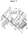
- Figure 9 is an enlarged cross-sectional view, in part similar to Figure 4, and shows another embodiment of the invention.
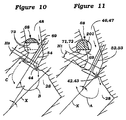
- Figure 10 is a cross-sectional view, in part similar to Figures 3 and 8 and shows another embodiment of the invention.
- Figure 11 is a cross-sectional view, in part similar to Figures 4 and 9 and shows another embodiment of the invention.
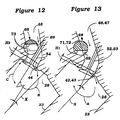
- Figure 12 is a cross-sectional view, in part similar to Figures 3, 8, and 10 and shows yet another embodiment of the invention.
- Figure 13 is a cross-sectional view, in part similar to Figures 4, 9, and 11, and shows yet another embodiment of the invention.
- Figure 14 is a cross-sectional view, in part similar to Figures 3, 8, 10, and 12 and shows a still further embodiment of the invention.
- Figure 15 is a cross-sectional view, in part similar to Figures 4, 9, 11, and 13, and shows yet another embodiment of the invention.
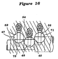
- Figure 16 is a cross-sectional view, in part similar to Figure 6 and shows a still further embodiment of the invention.
- an internal combustion engine constructed in accordance with this embodiment of the invention is identified generally by the reference numeral 21. Since the invention deals primarily with the induction system for the engine, only the upper portion of the engine 21 has been depicted and will be described. Where any details of the engine 21 are not described; they may be considered to be conventional. Also, for the most part, the invention is described in conjunction with only a single cylinder of the engine, although other cylinders appear in certain of the figures. It should be readily apparent to those skilled in the art that the invention may be practiced in conjunction with either single cylinder engines or multiple cylinder engines and multiple cylinder engines having various configurations.
- the engine 21 is comprised of a cylinder block 22 that has one or more cylinder bores 23 formed therein by pressed or cast-in cylinder liners 24. Obviously, the invention may be employed in conjunction with engines wherein the cylinder bores are formed directly by the cylinder block 22.
- the axis of the cylinder bore 23 is designated in certain of the figures by the line X.
- Pistons 25 are supported for reciprocation within the cylinder bores 23 and are connected by means of connecting rods 26 to a crank shaft (not shown) in a conventional manner.
- a cylinder head assembly indicated generally by the reference numeral 27 is affixed to the cylinder block 22 in a known manner and closes the cylinder bores 23.
- the cylinder head 27 is provided with recesses 29 which cooperate with the heads of the pistons 25 and the cylinder bores 23 to form variable volume chambers of the engine, which may be considered to be the combustion chambers.
- the engine 21 in all embodiments described is of the cross-flow pattern and therefore one side of the cylinder head, lying substantially on one side of a plane L x ( Figure 7) containing the axis X of the cylinder bore and passing through the rotational axis of the crankshaft is comprised of the intake side and this includes an induction system, indicated generally by the reference numeral 29.
- the opposite side comprises the exhaust side of the engine and contains the exhaust system, which will be described.
- the induction system 29 includes an arrangement for drawing atmospheric air and delivering it to the combustion chamber.
- This includes an air inlet device, shown partially and identified by the reference numeral 31 which draws atmospheric air and which may silence and filter this air.
- the air is then delivered, in the embodiments described, to a charge former in the form of a carburetor 32.
- a charge former in the form of a carburetor 32.
- the carburetors 32 are of the so-called air valve type and include manually operated throttle valves 31 which are operated under operator control in any well known manner.
- a sliding piston 34 is supported in the induction passage 35 of the carburetor 32 and has a metering rod 36 for controlling the fuel flow.
- the piston 34 also moves automatically in position in the induction passage 35 so as to maintain a substantially constant pressure differential for the flow through the carburetor 32.
- the carburetor 32 supplies the air fuel mixture to an intake manifold 37 which is affixed in a suitable manner to the cylinder head assembly 27 and which communicates with intake passages 38 formed in of the cylinder head assembly 27 beginning at an exterior surface 39.
- the induction passage 38 is of the siamese type and serves three intake ports formed by three intake valve seats comprised of a pair of side intake valve seats 42 and 43 and a center intake valve seat 44.
- the relation of these valve seats may be best seen in Figure 7 which is an underside view of the cylinder head assembly 27 it will be seen that the centers of the intake ports defined by the side intake valve seats 42 and 43 lie on a common line L1 that extends parallel to the plane L x containing the cylinder bore axes X and the axis of rotation of the crankshaft.
- the intake valve port formed by the center intake valve seat 44 lies on a line L2 which is spaced further from the plane L x as clearly shown in Figure 7.
- the orientation of the valve seats 42, 43, and 44 and the valves which are associated with them will be described in more detail later.
- the intake passage 38 is of the siamese type in this embodiment and it includes an inlet opening 45 which is formed in the outer surface 39 of the cylinder head assembly 27, as previously noted. This passage is then divided into three intake passages comprised of a pair of side intake passages 46 and 47 and a center intake passage 48 which intake passages are formed by internal walls 49 and 51 of the cylinder head assembly 27. It is to be understood that although the invention is described in conjunction with a siamese type of intake passage, the invention may be employed with induction systems wherein each intake valve seat 42, 43, and 44 is provided with its own intake passage or any pairs of the intake passages may be siamesed with each other.
- the center intake valve 54 is disposed so that its axis is disposed at an acute angle ⁇ 2 to the plane L x but that this acute angle ⁇ 2 is less than the acute angle ⁇ 1 of the planes containing the axes of the side poppet valves 52 and 53. It is to be understood that this is a preferred form of the valve placement but that other valve placements may be employed without departing from the spirit and scope of the invention.
- the intake valves 52, 53, and 54 may be disposed so that their reciprocal axes intersect at a common point although, again, this is not a necessary ingredient of the invention.
- the intake valves 52, 53, and 54 are all urged to their closed positions by means of coil compression springs 56 that are loaded between the cylinder head 27 and keeper retainer assemblies, as is well known in this art.
- Thimble tappets 57 are slidably supported in the cylinder head assembly 27 and are operated by an intake cam shaft 58 for opening and closing the intake valves 52, 53, and 54 in a well known manner.
- the intake cam shaft 58 is driven at one-half crankshaft speed by any suitable drive, as is also well known in this art.
- the cylinder head 27 is provided with siamesed exhaust passages 59 which communicate with exhaust ports formed by valve seats 61 formed in the cylinder head 27 in an appropriate manner.
- a pair of exhaust passages 62 that extend from the valve seat 61 to a common discharge opening 63 that is formed in the exhaust side of the cylinder head 27.
- Any suitable exhaust manifold may be provided for collecting the exhaust gases and discharging them to the atmosphere through any well known manner.
- Exhaust valves 64 are slidably supported within the cylinder head assembly 27 in valve guide 65 that are pressed or otherwise fixed to the cylinder head 27 and cooperate with the valve seat 61 so as to control the flow through the exhaust passage 58.
- the exhaust valves 64 are urged to their closed position by coil compression springs 56 and thimble tappets 57 are associated with the stems of each of the exhaust valves 64 for controlling their opening and closing.
- An overhead mounted exhaust cam shaft 66 which is driven at half crankshaft speed like the intake cam shaft 58 in journaled in the cylinder head assembly 27 and operates the thimble tappets 58 for operating the exhaust valve 64 in a well known manner.
- Spark plugs 67 are mounted in the cylinder head assembly 27 so that their spark gaps lie substantially on the cylinder bore axis X.
- the spark plugs 67 are fired by any suitable ignition circuit.
- the reciprocal axes for the exhaust valves 64 lie in a common plane and this common plane is disposed at an acute angle to the plane L x containing the axes X of the cylinder bore. This acute angle is between the acute angle ⁇ 2 of the center intake valve 44 and those ⁇ 2 of the side intake valves 42 and 43. Also, it would be noted that the center of the exhaust valve seats 61 or exhaust ports is disposed at a distance D3 from the plane L x which is less than the distance D1 of the plane L1 of the side intake valves and less than the distance D2 of the plane L2 containing the center intake valve 44. Again, this relationship is deemed to be only a preferred arrangement and the invention can be employed with engines having other placements.
- the intake passages 46, 47, and 48 are disposed so that they discharge into the combustion chamber and specifically the cylinder head recess 28 in a direction generally parallel to the cylinder bore axis X and in a generally unrestricted manner.
- Each of the intake passages 46, 47, and 48 is comprised of a generally straight portion which is disposed at an angle to the plane L x and a generally straight portion having a height H which extends generally parallel to the cylinder bore axes X so as to provide substantially unrestricted flow.
- the control valve assembly 68 is comprised of a generally cylindrical member that is rotatably journaled in the cylinder head assembly 27 within a bore 69 that extends substantially parallel to the plane L x and which intersects each of the intake passages 46, 47, and 48 at a point slightly above their bight in the illustrated embodiments. Because of this location, the control valve 68 will protrude further into the center intake passage 48 than it does into the side intake passages 46 and 47 as clearly shown in Figures 3 and 4. This has both structural and functional advantages in that it permits a single control valve 68 to be used for all of the intake passages 46, 47, and 48 for a given cylinder bore 23 and also assists in providing the desired flow pattern when the control valve 68 is rotated to change the flow pattern. This is possible even though the intake passages 46 and 47 have a different orientation than the intake passage 48 as clearly shown in Figure 2.
- the control valve 68 is provided with cutout portions 71 and 72 in the intake passages 46 and 47, respectively, and a cutout 73 in the intake passage 48.
- the cutouts 71 and 72 remove a lesser portion of the control valve 68 than the cutout 73 as clearly shown in Figures 3 and 4.
- the cutouts 71, 72, and 73 are configured so that when the control valve 68 is in a first wide open or full load running condition that there is absolutely no extension of the control valve 68 into the induction passages 46, 47, and 48, as noted in my aforenoted copending applications. Hence, unrestricted flow to the combustion chambers is possible in this position and good charging efficiency can be obtained. Also, no turbulence will be created in the combustion chambers under this condition.
- FIG 3 there is also generated a tumble action as indicated by the arrow B in this figure by the presence of the control valve 68 in occluding fashion to the intake passage 48.
- the valve seat 44 is disposed at a greater distance D2 from the plane L x the distance D1 of the side intake valves 42 and 43 so that the tumble action will not be as great.
- the height H2 of the straight section of the intake passage 48 is made shorter than the height H1 of the intake passages 46 and 47 so as to reduce the differences between the tumble flow from the center intake passage 48 from those of the side intake passages 46 and 47.
- control valve 68 may be operated by any suitable mechanism, as described in my aforenoted pending application, and that any kind of a control strategy may be employed. Basically, under low-speed, low-load conditions, the control valve 68 is placed in its second position as shown in the solid line views of the figures and then as the engine's speed and load increases, the control valves 68 are rotated in a step function toward their open position so as to reduce the turbulence and increase the charging efficiency.
- control valve 68 has been rotated in a clockwise direction from its closed position to its open position.
- the occluding portion of the control valve 68 in the center intake passage 48 will be closer to the valve seat as shown by the broken line view of Figure 3. This will tend to increase the amount of tumble generated by the center intake valve since the airflow path C counter to the tumble action will be substantially reduced.
- the amount of slant to the tumble direction can be controlled by changing certain parameters such as the heights H1 and H2 of the straight sections of the intake passages 46, 47, and 48. Also, the amount of cutouts for the respective portions 71,72, and 73 and the direction of rotation of the control valve 48 can effect this feature.
- This embodiment shows a way in which the counter-tumble flow C associated with the center intake valve seat 42 can be reduced. This is done by providing a slight recessing of the valve seat 42 so as to provide a generally cylindrical masking portion 101 which will tend to restrict the counter-tumble flow C. This concept may be used with any of the valve seats depending upon the flow pattern which is desired.
- Figure 9 shows another embodiment wherein the control valve 68 is positioned somewhat differently and is shaped differently so as to increase the swirl action.
- This can be utilized with either the center intake valve seat 44 or one of the side intake valve seats 42 or 43.
- this construction eliminates the separate pressed in valve seat but rather provides a coating or other type of surface finish 151 for shortening the straight section of the intake passage without adversely effecting its flow capabilities when running at high-speed and high-load.
- Similar treatments 152 may be provided for the valve seats of the exhaust valves 64.
- control valve 68 This permits the control valve 68 to be positioned lower and in the bight associated with the respective intake passage, this particular embodiment being depicted in conjunction with one of the side intake passages 46 or 47.
- the cutout portion, indicated generally by the reference numeral 153 is formed somewhat in an arcuate fashion so as to provide a continuation of the surface defining the intake passage 46 when the control valve is in its first or fully opened non-flow restricting position.
- the side surface of the control valve 68 is provided with a further notch or recess 154 so as to permit it to clear the item of the respective intake valve 52 and direct substantially all of the flow in the tumble path.
- Figures 10 and 11 are views similar to Figures 3 and 4, respectively, but these figures show how the amount of tumble action from the center intake passage 48 may be increased and the amount of tumble action from either or both of the side intake passages 46 and 47 may be reduced. This variation in tumble action between the side intake passages 46 and 47 and the center intake passage 48 will effect the amount of slant to the tumble action, as should be apparent. Because these embodiments differ from the previously described embodiments only in certain dimensional relationships and another structural distinction, which will be described, the reference numerals applied to the previous embodiment are utilized here.
- the height H1 of the straight portion of the side intake passages 46 and 47 in increased over the height H2 Of the straight section of the center intake passage 48. That will, in effect, increase the amount of tumble from the center intake passage 48 and reduce the amount of tumble from the side intake passages 46 and 47. Thus, with the arrangements previously described this will reduce the amount of slant to the tumble action.
- control valve may be rotated in a counterclockwise direction from its first position to its second position as shown in the dotted line view of Figure 10 so as to reduce the amount of counter-tumble flow C and increase the amount of tumble flow B.
- the amount of tumble action can also be varied and in fact reduced by providing a relief, indicated at 201 in Figure 11 in the control valve 68 so as to reduce the amount of flow redirection toward the cylinder bore axis X.
- Figures 12 and 13 show other embodiments which may be used with either the center or side intake passages 48, 46 and 47 and is generally similar to the embodiment of Figures 10 and 11.
- the side intake passages 46 and 47 have a lesser height H1 than the height H2 of the straight section of the center intake passage 48 so as to promote more tumble from the side intake passages 46 and 47 than the center intake passage 48.
- the cutout 201 is not employed so as to promote more tumble action for the side intake passages 46 and 47.
- Figures 14 and 15 show additional embodiments like those of Figures 3, 4, and 8-13 in that they depict other ways in which the amount of tumble action can be varied so as to provide the desired amount of slant to the overall tumble action in the cylinder bore.
- the height H1 of the straight portion of the side intake passages 46 and 47 is greater than the height H2 of the center intake passage 48 so as to increase the tumble action from the center intake passage 48 without significantly decreasing the tumble action from the side intake passages 46 and 47.
- This decreased tumble action is offset by employing a larger diameter section, 251 for the portion of the control valve 68 that goes through the side intake passages 46 and 47 so as to divert more flow toward the one side of the valve seats 42 and 43.
Landscapes
- Engineering & Computer Science (AREA)
- Mechanical Engineering (AREA)
- General Engineering & Computer Science (AREA)
- Chemical & Material Sciences (AREA)
- Combustion & Propulsion (AREA)
- Cylinder Crankcases Of Internal Combustion Engines (AREA)
- Valve-Gear Or Valve Arrangements (AREA)
Applications Claiming Priority (2)
| Application Number | Priority Date | Filing Date | Title |
|---|---|---|---|
| JP00519993A JP3402640B2 (ja) | 1993-01-14 | 1993-01-14 | エンジンの吸気制御装置 |
| JP5199/93 | 1993-01-14 |
Publications (2)
| Publication Number | Publication Date |
|---|---|
| EP0610678A1 true EP0610678A1 (fr) | 1994-08-17 |
| EP0610678B1 EP0610678B1 (fr) | 1998-12-23 |
Family
ID=11604538
Family Applications (2)
| Application Number | Title | Priority Date | Filing Date |
|---|---|---|---|
| EP94100517A Expired - Lifetime EP0610679B1 (fr) | 1993-01-14 | 1994-01-14 | Système d'aspiration pour un moteur |
| EP94100516A Expired - Lifetime EP0610678B1 (fr) | 1993-01-14 | 1994-01-14 | Système d'aspiration pour un moteur |
Family Applications Before (1)
| Application Number | Title | Priority Date | Filing Date |
|---|---|---|---|
| EP94100517A Expired - Lifetime EP0610679B1 (fr) | 1993-01-14 | 1994-01-14 | Système d'aspiration pour un moteur |
Country Status (3)
| Country | Link |
|---|---|
| EP (2) | EP0610679B1 (fr) |
| JP (1) | JP3402640B2 (fr) |
| DE (2) | DE69421426T2 (fr) |
Cited By (3)
| Publication number | Priority date | Publication date | Assignee | Title |
|---|---|---|---|---|
| EP0764773A3 (fr) * | 1995-09-22 | 1997-12-29 | AVL List GmbH | Moteur à combustion à quatre temps |
| DE19730842A1 (de) * | 1997-07-18 | 1999-01-21 | Audi Ag | Brennkraftmaschine |
| DE19735863A1 (de) * | 1997-08-19 | 1999-02-25 | Audi Ag | Brennkraftmaschine |
Families Citing this family (6)
| Publication number | Priority date | Publication date | Assignee | Title |
|---|---|---|---|---|
| DE19511136A1 (de) * | 1995-03-27 | 1996-05-23 | Daimler Benz Ag | Brennkraftmaschine |
| JP3562165B2 (ja) * | 1996-09-17 | 2004-09-08 | 日産自動車株式会社 | ディーゼルエンジンの吸気ポート |
| DE19710832A1 (de) * | 1997-03-15 | 1998-09-17 | Ford Global Tech Inc | Verfahren zum Betrieb eines Mehrzylinder-Verbrennungsmotors sowie Vorrichtung zur Durchführung des Verfahrens |
| DE102007020926A1 (de) * | 2007-05-04 | 2008-11-06 | GM Global Technology Operations, Inc., Detroit | Luftansaugkanal |
| DE102012012796A1 (de) | 2012-05-24 | 2013-11-28 | Daimler Ag | Brennkraftmaschine für ein Kraftfahrzeug |
| JP2016200042A (ja) * | 2015-04-09 | 2016-12-01 | 日産自動車株式会社 | エンジン |
Citations (5)
| Publication number | Priority date | Publication date | Assignee | Title |
|---|---|---|---|---|
| DE3609693A1 (de) * | 1985-03-22 | 1986-10-09 | Toyota Jidosha K.K., Toyota, Aichi | Brennkraftmaschine mit kraftstoffeinspritzung |
| US4617896A (en) * | 1985-03-14 | 1986-10-21 | Yamaha Hatsudoki Kabushiki Kaisha | Internal combustion engine having three intake valves per cylinder |
| DE4108469A1 (de) * | 1990-03-15 | 1991-09-19 | Mazda Motor | Einlassvorrichtung fuer einen mehrventilmotor |
| JPH04134126A (ja) * | 1990-09-27 | 1992-05-08 | Mazda Motor Corp | エンジンの燃焼室構造 |
| EP0500123A1 (fr) * | 1991-02-21 | 1992-08-26 | Yamaha Hatsudoki Kabushiki Kaisha | Système d'aspiration d'un moteur à combustion interne |
Family Cites Families (4)
| Publication number | Priority date | Publication date | Assignee | Title |
|---|---|---|---|---|
| JPS5724414A (en) * | 1980-07-18 | 1982-02-09 | Hino Motors Ltd | Cylinder head |
| US4974566A (en) * | 1989-09-28 | 1990-12-04 | Ford Motor Company | Optimal swirl generation by valve control |
| GB2242228A (en) * | 1990-03-24 | 1991-09-25 | Rover Group | I.c engine charge swirl inlet arrangement |
| EP0500124B1 (fr) * | 1991-02-21 | 1997-08-20 | Yamaha Hatsudoki Kabushiki Kaisha | Système d'aspiration d'un moteur à combustion interne |
-
1993
- 1993-01-14 JP JP00519993A patent/JP3402640B2/ja not_active Expired - Fee Related
-
1994
- 1994-01-14 EP EP94100517A patent/EP0610679B1/fr not_active Expired - Lifetime
- 1994-01-14 EP EP94100516A patent/EP0610678B1/fr not_active Expired - Lifetime
- 1994-01-14 DE DE69421426T patent/DE69421426T2/de not_active Expired - Fee Related
- 1994-01-14 DE DE69415356T patent/DE69415356T2/de not_active Expired - Fee Related
Patent Citations (5)
| Publication number | Priority date | Publication date | Assignee | Title |
|---|---|---|---|---|
| US4617896A (en) * | 1985-03-14 | 1986-10-21 | Yamaha Hatsudoki Kabushiki Kaisha | Internal combustion engine having three intake valves per cylinder |
| DE3609693A1 (de) * | 1985-03-22 | 1986-10-09 | Toyota Jidosha K.K., Toyota, Aichi | Brennkraftmaschine mit kraftstoffeinspritzung |
| DE4108469A1 (de) * | 1990-03-15 | 1991-09-19 | Mazda Motor | Einlassvorrichtung fuer einen mehrventilmotor |
| JPH04134126A (ja) * | 1990-09-27 | 1992-05-08 | Mazda Motor Corp | エンジンの燃焼室構造 |
| EP0500123A1 (fr) * | 1991-02-21 | 1992-08-26 | Yamaha Hatsudoki Kabushiki Kaisha | Système d'aspiration d'un moteur à combustion interne |
Non-Patent Citations (1)
| Title |
|---|
| PATENT ABSTRACTS OF JAPAN vol. 16, no. 399 (M - 1300) 24 August 1992 (1992-08-24) * |
Cited By (3)
| Publication number | Priority date | Publication date | Assignee | Title |
|---|---|---|---|---|
| EP0764773A3 (fr) * | 1995-09-22 | 1997-12-29 | AVL List GmbH | Moteur à combustion à quatre temps |
| DE19730842A1 (de) * | 1997-07-18 | 1999-01-21 | Audi Ag | Brennkraftmaschine |
| DE19735863A1 (de) * | 1997-08-19 | 1999-02-25 | Audi Ag | Brennkraftmaschine |
Also Published As
| Publication number | Publication date |
|---|---|
| JP3402640B2 (ja) | 2003-05-06 |
| DE69421426D1 (de) | 1999-12-09 |
| EP0610679A1 (fr) | 1994-08-17 |
| DE69415356T2 (de) | 1999-05-06 |
| JPH06212983A (ja) | 1994-08-02 |
| EP0610678B1 (fr) | 1998-12-23 |
| EP0610679B1 (fr) | 1999-11-03 |
| DE69415356D1 (de) | 1999-02-04 |
| DE69421426T2 (de) | 2000-05-04 |
Similar Documents
| Publication | Publication Date | Title |
|---|---|---|
| US6148794A (en) | Induction control system for multi-valve engine | |
| US5487365A (en) | Induction system for engine | |
| US5913298A (en) | Valve timing system for engine | |
| US4617896A (en) | Internal combustion engine having three intake valves per cylinder | |
| US5740767A (en) | Scavenge control for engine | |
| EP0703355A2 (fr) | Moteur à combustion interne | |
| US5477823A (en) | Control valve for engine intake control system | |
| USRE37289E1 (en) | Induction system for engine | |
| US5255649A (en) | Intake air control system for the engine | |
| US4520775A (en) | Intake system for multiple valve type engine | |
| US5671712A (en) | Induction system for engine | |
| US5762041A (en) | Four-stroke internal combustion engine | |
| US5826560A (en) | Engine combustion chamber and method of operation | |
| EP0610678B1 (fr) | Système d'aspiration pour un moteur | |
| US5564383A (en) | Tumble valve arrangement for engine | |
| EP0595316B1 (fr) | Culasse et disposition de soupapes d'un moteur à combustion interne multisoupape | |
| US5549088A (en) | Induction system for engine | |
| US5636613A (en) | Cylinder head porting arrangement for multi-valve engine | |
| US5787851A (en) | Intake control system | |
| US7273032B2 (en) | Engine induction system | |
| US5806484A (en) | Induction control system for engine | |
| JPH0745817B2 (ja) | 直噴式多気筒ディーゼル機関 | |
| EP0520518B1 (fr) | Système d'admission pour un moteur à combustion interne | |
| US4381749A (en) | Intake device for engine | |
| US4292944A (en) | Intake control system for internal combustion engine |
Legal Events
| Date | Code | Title | Description |
|---|---|---|---|
| PUAI | Public reference made under article 153(3) epc to a published international application that has entered the european phase |
Free format text: ORIGINAL CODE: 0009012 |
|
| AK | Designated contracting states |
Kind code of ref document: A1 Designated state(s): DE FR GB |
|
| 17P | Request for examination filed |
Effective date: 19950216 |
|
| 17Q | First examination report despatched |
Effective date: 19951124 |
|
| GRAG | Despatch of communication of intention to grant |
Free format text: ORIGINAL CODE: EPIDOS AGRA |
|
| GRAG | Despatch of communication of intention to grant |
Free format text: ORIGINAL CODE: EPIDOS AGRA |
|
| GRAH | Despatch of communication of intention to grant a patent |
Free format text: ORIGINAL CODE: EPIDOS IGRA |
|
| GRAH | Despatch of communication of intention to grant a patent |
Free format text: ORIGINAL CODE: EPIDOS IGRA |
|
| GRAA | (expected) grant |
Free format text: ORIGINAL CODE: 0009210 |
|
| AK | Designated contracting states |
Kind code of ref document: B1 Designated state(s): DE FR GB |
|
| PG25 | Lapsed in a contracting state [announced via postgrant information from national office to epo] |
Ref country code: FR Free format text: LAPSE BECAUSE OF FAILURE TO SUBMIT A TRANSLATION OF THE DESCRIPTION OR TO PAY THE FEE WITHIN THE PRESCRIBED TIME-LIMIT Effective date: 19981223 |
|
| REF | Corresponds to: |
Ref document number: 69415356 Country of ref document: DE Date of ref document: 19990204 |
|
| PG25 | Lapsed in a contracting state [announced via postgrant information from national office to epo] |
Ref country code: GB Free format text: LAPSE BECAUSE OF NON-PAYMENT OF DUE FEES Effective date: 19990323 |
|
| EN | Fr: translation not filed | ||
| PLBE | No opposition filed within time limit |
Free format text: ORIGINAL CODE: 0009261 |
|
| STAA | Information on the status of an ep patent application or granted ep patent |
Free format text: STATUS: NO OPPOSITION FILED WITHIN TIME LIMIT |
|
| GBPC | Gb: european patent ceased through non-payment of renewal fee |
Effective date: 19990323 |
|
| 26N | No opposition filed | ||
| PGFP | Annual fee paid to national office [announced via postgrant information from national office to epo] |
Ref country code: DE Payment date: 20060112 Year of fee payment: 13 |
|
| PG25 | Lapsed in a contracting state [announced via postgrant information from national office to epo] |
Ref country code: DE Free format text: LAPSE BECAUSE OF NON-PAYMENT OF DUE FEES Effective date: 20070801 |