EP0610708B1 - Pompe doseuse - Google Patents
Pompe doseuse Download PDFInfo
- Publication number
- EP0610708B1 EP0610708B1 EP94100983A EP94100983A EP0610708B1 EP 0610708 B1 EP0610708 B1 EP 0610708B1 EP 94100983 A EP94100983 A EP 94100983A EP 94100983 A EP94100983 A EP 94100983A EP 0610708 B1 EP0610708 B1 EP 0610708B1
- Authority
- EP
- European Patent Office
- Prior art keywords
- valve
- dosing pump
- fact
- pump according
- aforementioned
- Prior art date
- Legal status (The legal status is an assumption and is not a legal conclusion. Google has not performed a legal analysis and makes no representation as to the accuracy of the status listed.)
- Expired - Lifetime
Links
- 239000000919 ceramic Substances 0.000 claims abstract description 27
- 239000007788 liquid Substances 0.000 claims abstract description 23
- 229910052581 Si3N4 Inorganic materials 0.000 claims abstract description 13
- HQVNEWCFYHHQES-UHFFFAOYSA-N silicon nitride Chemical compound N12[Si]34N5[Si]62N3[Si]51N64 HQVNEWCFYHHQES-UHFFFAOYSA-N 0.000 claims abstract description 13
- 229910052782 aluminium Inorganic materials 0.000 claims abstract description 11
- XAGFODPZIPBFFR-UHFFFAOYSA-N aluminium Chemical compound [Al] XAGFODPZIPBFFR-UHFFFAOYSA-N 0.000 claims abstract description 11
- 229910001338 liquidmetal Inorganic materials 0.000 claims abstract description 8
- 239000004411 aluminium Substances 0.000 claims abstract 2
- 229910000831 Steel Inorganic materials 0.000 claims description 5
- 239000010959 steel Substances 0.000 claims description 5
- 238000005299 abrasion Methods 0.000 abstract 1
- 229910010293 ceramic material Inorganic materials 0.000 description 7
- 238000011161 development Methods 0.000 description 6
- 230000018109 developmental process Effects 0.000 description 6
- 238000004519 manufacturing process Methods 0.000 description 5
- 229910052751 metal Inorganic materials 0.000 description 5
- 239000002184 metal Substances 0.000 description 5
- 238000005245 sintering Methods 0.000 description 4
- OYPRJOBELJOOCE-UHFFFAOYSA-N Calcium Chemical compound [Ca] OYPRJOBELJOOCE-UHFFFAOYSA-N 0.000 description 3
- 229910052791 calcium Inorganic materials 0.000 description 3
- 239000011575 calcium Substances 0.000 description 3
- 230000002349 favourable effect Effects 0.000 description 3
- 239000000463 material Substances 0.000 description 3
- 238000005086 pumping Methods 0.000 description 3
- XUIMIQQOPSSXEZ-UHFFFAOYSA-N Silicon Chemical compound [Si] XUIMIQQOPSSXEZ-UHFFFAOYSA-N 0.000 description 2
- MCMNRKCIXSYSNV-UHFFFAOYSA-N Zirconium dioxide Chemical compound O=[Zr]=O MCMNRKCIXSYSNV-UHFFFAOYSA-N 0.000 description 2
- 229910052787 antimony Inorganic materials 0.000 description 2
- WATWJIUSRGPENY-UHFFFAOYSA-N antimony atom Chemical compound [Sb] WATWJIUSRGPENY-UHFFFAOYSA-N 0.000 description 2
- 230000006835 compression Effects 0.000 description 2
- 238000007906 compression Methods 0.000 description 2
- 230000007423 decrease Effects 0.000 description 2
- 230000001419 dependent effect Effects 0.000 description 2
- 238000004512 die casting Methods 0.000 description 2
- -1 ferrous metals Chemical class 0.000 description 2
- 229910052574 oxide ceramic Inorganic materials 0.000 description 2
- 229910052710 silicon Inorganic materials 0.000 description 2
- 239000010703 silicon Substances 0.000 description 2
- HBMJWWWQQXIZIP-UHFFFAOYSA-N silicon carbide Chemical compound [Si+]#[C-] HBMJWWWQQXIZIP-UHFFFAOYSA-N 0.000 description 2
- 229910010271 silicon carbide Inorganic materials 0.000 description 2
- 239000000243 solution Substances 0.000 description 2
- 125000006850 spacer group Chemical group 0.000 description 2
- 229910001220 stainless steel Inorganic materials 0.000 description 2
- 239000010935 stainless steel Substances 0.000 description 2
- 229910052582 BN Inorganic materials 0.000 description 1
- PZNSFCLAULLKQX-UHFFFAOYSA-N Boron nitride Chemical compound N#B PZNSFCLAULLKQX-UHFFFAOYSA-N 0.000 description 1
- RYGMFSIKBFXOCR-UHFFFAOYSA-N Copper Chemical compound [Cu] RYGMFSIKBFXOCR-UHFFFAOYSA-N 0.000 description 1
- HCHKCACWOHOZIP-UHFFFAOYSA-N Zinc Chemical compound [Zn] HCHKCACWOHOZIP-UHFFFAOYSA-N 0.000 description 1
- PNEYBMLMFCGWSK-UHFFFAOYSA-N aluminium oxide Inorganic materials [O-2].[O-2].[O-2].[Al+3].[Al+3] PNEYBMLMFCGWSK-UHFFFAOYSA-N 0.000 description 1
- 238000006243 chemical reaction Methods 0.000 description 1
- 229910052802 copper Inorganic materials 0.000 description 1
- 239000010949 copper Substances 0.000 description 1
- 230000007797 corrosion Effects 0.000 description 1
- 238000005260 corrosion Methods 0.000 description 1
- 230000006735 deficit Effects 0.000 description 1
- 230000006866 deterioration Effects 0.000 description 1
- 238000006073 displacement reaction Methods 0.000 description 1
- 238000005516 engineering process Methods 0.000 description 1
- 230000003628 erosive effect Effects 0.000 description 1
- 239000004744 fabric Substances 0.000 description 1
- 238000002347 injection Methods 0.000 description 1
- 239000007924 injection Substances 0.000 description 1
- 239000000314 lubricant Substances 0.000 description 1
- 230000001050 lubricating effect Effects 0.000 description 1
- 238000005461 lubrication Methods 0.000 description 1
- 230000007257 malfunction Effects 0.000 description 1
- 239000000155 melt Substances 0.000 description 1
- 150000002739 metals Chemical class 0.000 description 1
- 238000000034 method Methods 0.000 description 1
- 150000004767 nitrides Chemical class 0.000 description 1
- 230000002093 peripheral effect Effects 0.000 description 1
- 230000001737 promoting effect Effects 0.000 description 1
- 238000007789 sealing Methods 0.000 description 1
- 230000035939 shock Effects 0.000 description 1
- 239000007787 solid Substances 0.000 description 1
- 229910052725 zinc Inorganic materials 0.000 description 1
- 239000011701 zinc Substances 0.000 description 1
Images


Classifications
-
- F—MECHANICAL ENGINEERING; LIGHTING; HEATING; WEAPONS; BLASTING
- F04—POSITIVE - DISPLACEMENT MACHINES FOR LIQUIDS; PUMPS FOR LIQUIDS OR ELASTIC FLUIDS
- F04B—POSITIVE-DISPLACEMENT MACHINES FOR LIQUIDS; PUMPS
- F04B15/00—Pumps adapted to handle specific fluids, e.g. by selection of specific materials for pumps or pump parts
- F04B15/04—Pumps adapted to handle specific fluids, e.g. by selection of specific materials for pumps or pump parts the fluids being hot or corrosive
-
- C—CHEMISTRY; METALLURGY
- C04—CEMENTS; CONCRETE; ARTIFICIAL STONE; CERAMICS; REFRACTORIES
- C04B—LIME, MAGNESIA; SLAG; CEMENTS; COMPOSITIONS THEREOF, e.g. MORTARS, CONCRETE OR LIKE BUILDING MATERIALS; ARTIFICIAL STONE; CERAMICS; REFRACTORIES; TREATMENT OF NATURAL STONE
- C04B35/00—Shaped ceramic products characterised by their composition; Ceramics compositions; Processing powders of inorganic compounds preparatory to the manufacturing of ceramic products
- C04B35/515—Shaped ceramic products characterised by their composition; Ceramics compositions; Processing powders of inorganic compounds preparatory to the manufacturing of ceramic products based on non-oxide ceramics
- C04B35/58—Shaped ceramic products characterised by their composition; Ceramics compositions; Processing powders of inorganic compounds preparatory to the manufacturing of ceramic products based on non-oxide ceramics based on borides, nitrides, i.e. nitrides, oxynitrides, carbonitrides or oxycarbonitrides or silicides
- C04B35/584—Shaped ceramic products characterised by their composition; Ceramics compositions; Processing powders of inorganic compounds preparatory to the manufacturing of ceramic products based on non-oxide ceramics based on borides, nitrides, i.e. nitrides, oxynitrides, carbonitrides or oxycarbonitrides or silicides based on silicon nitride
- C04B35/593—Shaped ceramic products characterised by their composition; Ceramics compositions; Processing powders of inorganic compounds preparatory to the manufacturing of ceramic products based on non-oxide ceramics based on borides, nitrides, i.e. nitrides, oxynitrides, carbonitrides or oxycarbonitrides or silicides based on silicon nitride obtained by pressure sintering
-
- F—MECHANICAL ENGINEERING; LIGHTING; HEATING; WEAPONS; BLASTING
- F04—POSITIVE - DISPLACEMENT MACHINES FOR LIQUIDS; PUMPS FOR LIQUIDS OR ELASTIC FLUIDS
- F04B—POSITIVE-DISPLACEMENT MACHINES FOR LIQUIDS; PUMPS
- F04B53/00—Component parts, details or accessories not provided for in, or of interest apart from, groups F04B1/00 - F04B23/00 or F04B39/00 - F04B47/00
- F04B53/10—Valves; Arrangement of valves
- F04B53/108—Valves characterised by the material
-
- F—MECHANICAL ENGINEERING; LIGHTING; HEATING; WEAPONS; BLASTING
- F04—POSITIVE - DISPLACEMENT MACHINES FOR LIQUIDS; PUMPS FOR LIQUIDS OR ELASTIC FLUIDS
- F04B—POSITIVE-DISPLACEMENT MACHINES FOR LIQUIDS; PUMPS
- F04B53/00—Component parts, details or accessories not provided for in, or of interest apart from, groups F04B1/00 - F04B23/00 or F04B39/00 - F04B47/00
- F04B53/14—Pistons, piston-rods or piston-rod connections
-
- F—MECHANICAL ENGINEERING; LIGHTING; HEATING; WEAPONS; BLASTING
- F04—POSITIVE - DISPLACEMENT MACHINES FOR LIQUIDS; PUMPS FOR LIQUIDS OR ELASTIC FLUIDS
- F04B—POSITIVE-DISPLACEMENT MACHINES FOR LIQUIDS; PUMPS
- F04B53/00—Component parts, details or accessories not provided for in, or of interest apart from, groups F04B1/00 - F04B23/00 or F04B39/00 - F04B47/00
- F04B53/14—Pistons, piston-rods or piston-rod connections
- F04B53/144—Adaptation of piston-rods
- F04B53/147—Mounting or detaching of piston rod
-
- F—MECHANICAL ENGINEERING; LIGHTING; HEATING; WEAPONS; BLASTING
- F04—POSITIVE - DISPLACEMENT MACHINES FOR LIQUIDS; PUMPS FOR LIQUIDS OR ELASTIC FLUIDS
- F04B—POSITIVE-DISPLACEMENT MACHINES FOR LIQUIDS; PUMPS
- F04B53/00—Component parts, details or accessories not provided for in, or of interest apart from, groups F04B1/00 - F04B23/00 or F04B39/00 - F04B47/00
- F04B53/16—Casings; Cylinders; Cylinder liners or heads; Fluid connections
- F04B53/162—Adaptations of cylinders
- F04B53/166—Cylinder liners
-
- F—MECHANICAL ENGINEERING; LIGHTING; HEATING; WEAPONS; BLASTING
- F05—INDEXING SCHEMES RELATING TO ENGINES OR PUMPS IN VARIOUS SUBCLASSES OF CLASSES F01-F04
- F05C—INDEXING SCHEME RELATING TO MATERIALS, MATERIAL PROPERTIES OR MATERIAL CHARACTERISTICS FOR MACHINES, ENGINES OR PUMPS OTHER THAN NON-POSITIVE-DISPLACEMENT MACHINES OR ENGINES
- F05C2203/00—Non-metallic inorganic materials
- F05C2203/08—Ceramics; Oxides
- F05C2203/0804—Non-oxide ceramics
- F05C2203/083—Nitrides
-
- F—MECHANICAL ENGINEERING; LIGHTING; HEATING; WEAPONS; BLASTING
- F05—INDEXING SCHEMES RELATING TO ENGINES OR PUMPS IN VARIOUS SUBCLASSES OF CLASSES F01-F04
- F05C—INDEXING SCHEME RELATING TO MATERIALS, MATERIAL PROPERTIES OR MATERIAL CHARACTERISTICS FOR MACHINES, ENGINES OR PUMPS OTHER THAN NON-POSITIVE-DISPLACEMENT MACHINES OR ENGINES
- F05C2203/00—Non-metallic inorganic materials
- F05C2203/08—Ceramics; Oxides
- F05C2203/0804—Non-oxide ceramics
- F05C2203/083—Nitrides
- F05C2203/0843—Nitrides of silicon
Definitions
- the invention relates to a metering pump for liquids, in particular liquid metals, in particular lead or Aluminum, according to the preamble of claim 1.
- liquid metals such as lead or Aluminum or other non-ferrous metals are very aggressive are. If such liquid metals with components of the pump come into contact, there are chemical reactions, one Have a corrosive and erosive effect on the pump parts. This can lead to the metering accuracy of the pump decreases significantly after just a short period of operation. Further the pump can operate after a short period of operation become inoperable.
- the plunges Pump When dosing lead by means of a piston pump, the plunges Pump generally into the liquid lead.
- technical lead is used, so-called technical lead is used, so none chemically pure lead, but lead that - from batch to batch different - more or less with different fabrics is contaminated.
- the lead which is mainly for the Manufacture of batteries is used with other components alloyed, for example with antimony or - after one newer technology that is currently being developed - with Calcium.
- the lead alloyed with antimony is less aggressive and, with certain restrictions, can still use one Dosing pump made of steel become. This is hardly the case with lead alloyed with calcium or no longer possible because calcium oxidizes and itself still connects with other metals.
- DE-AS 12 78 to solve the problems described 248 have been proposed for a piston pump for delivery molten non-ferrous metals such as aluminum, Zinc, copper the pump housing, the piston, the valve balls and the limit pins made of silicon nitride-bonded silicon carbide, that is to say from a ceramic material.
- the entire pump should be completely in the weld pool is immersed, from the ceramic material mentioned getting produced.
- the displacement part a piston pump, especially a high pressure pump for abrasive and / or corrosive liquids, made of sintered, to produce ceramic, in particular oxide-ceramic material.
- Ceramic materials are sintered bodies made of sintered nitrides, for example silicon nitride, Borides, titanates and oxide ceramic materials understood how they as alumina ceramics and zirconia ceramics are known.
- the ceramic piston As such comes with it pumping medium in contact with the piston by cuffs is sealed in the cylinder chamber.
- an injection pump which has a housing, a cylinder and a piston.
- the Housing is made of a material with good corrosion resistance and sufficient mechanical strength.
- the object of the invention is to provide a metering pump for liquids, especially liquid metals, especially lead or aluminum, to propose according to the preamble of claim 1 has a high wear resistance.
- the housing consists of a lower housing part and an upper housing part, which by Tie rods and sleeves are clamped together, the cylinder being held between the housing parts. This will increases wear resistance.
- the cylinder and the piston are preferably made of silicon nitride.
- the or the exist Valve body and the valve seats made of ceramic, in particular Silicon nitride.
- the silicon nitride is preferably a So-called “hipped” silicon nitride, which sintered and has been resintered.
- the first sintering is preferred a "normal” sintering after a conventional one Sintering process, the second sintering preferably consists of a hot isostatic pressure.
- the invention is based on the knowledge that the manufacture an entire metering piston pump made of ceramic material, as described in DE-AS 12 78 248, in practice - if at all - is only possible with very great difficulty and that it is not necessary at all, the whole Dosing pump, i.e. all its components, from one manufacture ceramic material. Accordingly exist in the metering pump of the cylinder and the Ceramic pistons.
- the remaining parts of the dosing pump, especially the housing can be made of other materials, especially steel, preferably stainless steel, consist.
- valve body or bodies and / or the valve seats made of ceramic, in particular silicon nitride consist.
- the valve body or bodies and / or the valve seats use the same ceramic material as for the cylinder and the piston.
- the invention is based on the knowledge that through the promoting medium caused surface impairment of the Components of the pump, particularly in the case of the moving pump parts, in other words, those pump parts that are relative to each other execute, is particularly harmful. Therefore be these pump parts (cylinder and piston as well as if necessary Valve body and / or valve seats) made of ceramic. At the other pump parts that have no movements or relative movements to each other, can be promoted by the Medium in which the pump is immersed causes surface deterioration still acceptable, which is why this non-moving pump parts made of other materials could be.
- the ceramic used for the moving pump parts should be one relatively high temperature and preferably one relatively can withstand a large temperature shock. If the Dosing pump used for pumping and dosing liquid lead the pump is immersed in the liquid lead from an ambient temperature of around 20 ° C very much quickly to the temperature of the liquid lead in the amount of about 500 ° C warmed.
- dosing liquid aluminum is the temperature of the liquid to be pumped and dosed Aluminum about 750 ° C. Liquid aluminum must be used in particular Die casting machines or pre-dosing for aluminum die casting machines promoted and dosed.
- the one used Ceramic should also be as chemically resistant as possible Metal melts and their oxides.
- the ceramic should also have very good dry running properties to have. If ceramic surfaces within the normal air atmosphere moving against each other usually does not arise complete dry running, as there is always something in the air atmosphere Moisture is present, which causes some residual lubrication. Solid lead (i.e. non-liquid lead) is proportionate good sliding properties and is sometimes used as Lubricant used. With liquid lead, into which the dosing pump but it is completely different. Liquid Lead has no lubricating properties at all, so with one A 100% dosing pump immersed in liquid lead Dry running takes place. Accordingly, the ceramic has to do this have suitable sliding properties. The ceramic used should also be as wear-resistant as possible.
- Silicon nitride is particularly suitable for carrying out the invention is. It is particularly more suitable than that in the DE-AS 12 78 248 described silicon nitride-bonded silicon carbide.
- the piston preferably has a U-shaped cross section.
- the point of attachment of the piston rod to the piston can then be relocated to the inside of the piston, especially under Strength aspects is favorable.
- the wall thickness of the cylinder is essentially the same size as the wall thickness of the piston. This is in terms of thermal expansion of cylinders and pistons cheap.
- the wall thickness of the piston crown is preferably essentially as large as the wall thickness of the piston circumference.
- This too Solution is special in terms of thermal expansion Advantage, especially if the wall thickness of the cylinder is essentially the same size as the wall thickness of the Piston crown and the piston circumference.
- the piston has a U-shaped cross section and are the wall thicknesses of the cylinder, the piston circumference and the piston crown essentially the same size.
- the piston rod connected to the piston in the area of the piston crown. This will exert the force exerted by the piston rod on the piston Forces are particularly advantageously introduced into the piston, which is particularly the case with those with significantly higher forces associated pressure stroke has a favorable effect.
- the force application point the piston rod should be in the piston as close as possible to the piston crown lie.
- the piston and cylinder of the metering pump should be extremely accurate be made to leak through the fit of the piston to avoid in the cylinder. This would become one Reduce the dosing accuracy. Furthermore, the Clamp the piston in the cylinder. The fit between the piston and Cylinder should also be extremely accurate because it is for the Ceramic generally did not use pistons and cylinders is elastically deformable. For a particularly precise fit of the To reach the piston in the cylinder during operation according to a further advantageous development of the invention suggested using the piston through a gimbal to connect the piston rod. This can be particularly advantageous can be realized in that the piston rod by a ball joint is connected to the piston. Through the gimbal Bearing the piston on the piston rod can cause tension or Tensions are avoided, which lead to a decrease in the dosing accuracy and can cause the piston to jam.
- the tie rods are preferred against the sleeves over springs, especially disc springs tense together. These springs can cause thermal expansion be balanced. Even if such thermal expansion during the operation occurs, is always a by the springs sufficient tension of a lower and an upper Housing part of the existing housing are maintained the two housing parts are then reliably clamped against one another, if thermal expansion is caused by temperature differences be, for example, that the pump, the first has an ambient temperature of about 20 ° C, in which hot molten metal with a temperature of, for example 500 ° C (with liquid lead) or 750 ° C (with liquid Aluminum) is immersed. If the tie rods are exposed to heat expand, the disc springs ensure a corresponding Compensation for thermal expansion. It should be taken into account that steel, from which the housing parts are preferably made are a much larger coefficient of thermal expansion has as ceramic, so it is essential when exposed to heat expands more, about a factor of 10.
- the surface of the valve body in whole or in part consists of a spherical surface and that the valve seats a have a conical surface.
- the reverse configuration is possible: Then the surface of the valve body wholly or partly conical, and the valve seats have one spherical surface.
- valve an actively operated valve.
- This valve can be pneumatic be operated.
- the reversal of the valve is dependent from the position of the piston, preferably at the top and bottom dead center of the piston. For this are on the piston rod appropriate sensors are provided.
- the pressure channel of the valve is preferably located on that Side of the valve body, that of the actuating the valve body Valve rod is turned away. This will be the advantage achieved that the through opening of the valve rod through the pump housing does not have to be sealed, which may be the case would be difficult or impossible at all, especially in the conveying and dosing of liquid lead a temperature of about 500 ° C. Otherwise, in the of a return flow to the pump leading pressure line could lead to malfunctions and dosage errors.
- a self-steering Pressure valve and a self-controlling suction valve available.
- no active valve is provided, but two passive valves, preferably one Ceramic ball and a ceramic valve seat exist, the Valve seat preferably consists of a conical surface.
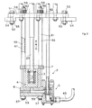
- the metering pump designated as a whole in FIG. 1 consists of 1 from a housing 2 with a cylinder 3, in which a piston 4 is guided longitudinally, and from a valve 5.
- the Cylinder 3 and piston 4 are made of ceramic, namely silicon nitride, manufactured.
- the housing 2, consisting of the lower Housing part 6 and the upper housing part 7, is made of stainless steel manufactured.
- the metering pump is on an enlarged scale shown.
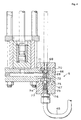
- a suction and Pressure channel 8 incorporated, which consists of a coaxial to the piston 4th extending in the upper end surface of the lower housing part 6 ending channel 9 and a right next to it the peripheral surface of the lower housing part 6 opening channel 10 consists.
- a valve housing on the side 11 connected, which consists of an upper valve housing part 12 and a lower valve housing part 13, which together are clamped by bolts 14 and nuts 15.
- the valve body parts 12, 13 lie on lugs 15 in the lower housing part 6 on.
- the valve 5 consists of a valve body 60 and a suction valve seat 50 and a pressure valve seat 16.
- the valve body 60 and the valve seats 50, 16 are made of ceramic, namely silicon nitride, manufactured.
- the upper end surface 17 and the lower end surface 18 of the valve body 60 are designed as partial spherical surfaces.
- the associated valve seat surfaces 19 and 20 of the valve seats 16 and 50 are conical surfaces with an angle of 45 ° educated.
- the piston 4 has a U-shaped cross section. It exists from a substantially cylindrical jacket part 21 and a Piston base 22.
- the wall thickness of the cylinder 3 is essentially the same size as the wall thickness of the piston 4, namely both the jacket part 21 and the piston crown 22 (in the Drawing of Fig. 3 is the piston crown 22 with a larger one Drawn wall thickness; is actually the wall thickness of the piston crown 22 but the same size as the wall thickness of the piston skirt 21 and how the wall thickness of the cylinder 3).
- the piston rod 23 is connected to the piston 4 via a ball joint 24 connected.
- a ball joint 24 connected to the piston rod 23 at the lower end of the piston rod 23 is an internal thread 25 provided, in which an intermediate piece 26 to one a stop forming paragraph 27 is screwed.
- the lower end surface as a spherical surface for the Ball joint is formed (not shown in the drawing).
- the ball (also not shown in the drawing) of the ball joint 24 lies with its underside on a corresponding one spherical counter surface on which in the bearing part 29 is formed.
- the bearing part 29 lies on a spacer ring 30 on, which in turn on the upper end surface of the piston crown 22 rests.
- Piston 4 In the recess 31 of the U-shaped cross section Piston 4 is arranged a piston sleeve 32, the upper one End face is supported on a fastening ring (Seeger ring) 33, which lies in a groove 34 of the piston skirt 21. Further the piston sleeve 32 has an inward projection 35 on the underside of which the paragraph 28 of the intermediate piece 26th is supported.
- the piston rod 23 is proportional in this way connected to the piston 4 close to the piston crown 22.
- the piston rod 23 exerted force on the paragraph 28, the projection 35, the Piston sleeve 32 and the fastening ring 33 on the piston 4 transfer.
- the lower one Ball joint bearing part 29 and the spacer ring 30 directly in the Piston plate 22 initiated.
- the valve 5 is designed as an actively operated control valve.
- the valve body 60 is penetrated by a valve rod 36.
- valve body 60 It lies with its lower end face on one at the lower end the valve rod 36 provided, larger diameter collar 37 'on.
- the valve body 60 becomes on its upper end surface clamped by a valve sleeve 37 surrounding the valve rod 36, which is clamped at its upper end with the valve rod 36 is (see Fig. 1), namely by an external thread the valve rod 36 arranged nut 38, which has a Press disk 39 onto the upper end of valve sleeve 37.
- the suction channel of the valve 5 consists of an input channel 40 and one coaxial with the valve rod 36 and the valve sleeve 37 Channel 41. At the lower end of channel 41 sits upper valve seat, that is, the pressure valve seat 16, in one paragraph in the upper valve housing part 11.
- the pressure channel consists of an outlet channel 42 and one Channel 43, which is coaxial with the valve rod 36 and the suction channel 41 runs.
- a connector 44 screwed, to which the pressure line 45 connects.
- the valve 5 becomes dependent on the movement of the piston 4 controlled, namely by a pneumatic drive 46 (Fig. 1).
- the valve rod 36 is with the piston rod of the pneumatic drive 46 connected via a ball joint 47.
- the housing 2 of the pump is on one Mounting plate 51 attached.
- the mounting plate 51 is on both sides by bolts 52 and nuts 53 with support plates 54 connected, which rest on the edge of the crucible.
- the surface of the liquid to be dosed runs between the support plates 54 and the upper housing part 7.
- the pump housing 2 with the piston 4 and the cylinder 3 and the valve housing 5 completely immerse in the dosing in this way Liquid.
- the mounting plate 51 has holes that go from the bottom projecting tie rods 55 are penetrated. Push through the tie rods 55 Bores in the upper housing part 7 and the lower Housing part 6.
- the tie rods have 55 external threads at their ends 56, 57 on, screwed onto the fastening nuts 58, 59 are.
- the Tie rod 55 In the area between the bottom of the mounting plate 51 and the top of the upper housing part 7 are the Tie rod 55 surrounded by sleeves 61 on the underside of the Mounting plate 51 and on the top of the upper housing part 7 and the clamped by the nuts 58, 59 are.
- the tie rods 55 are also against the sleeves 61 via springs, namely disc springs 62, tensioned. Form these disc springs 62 one set of disc springs each.
- the plate springs 62 are located between the top of the mounting plate 51 and the bottom the nuts 58; they are tense in this way. By the plate springs 62 can compensate for thermal expansion, which arise in particular if they are at ambient temperature pump in the hot liquid to be dosed is immersed.
- the piston rod 23 is driven by a pneumatic drive 63 (FIG. 1) driven.
- the piston rod 64 of the pneumatic drive 63 is over a ball joint 65 is connected to the piston rod 23 of the pump.
- Valve 5 is not an actively operated valve, but a passive valve, consisting of a self-controlling suction valve 66 and a self-regulating pressure valve 67.
- the liquid to be dosed is supplied to the suction valve 66 through the suction line 68.
- the suction valve 66 consists of a valve ball 69 and a Valve seat 70, which has a conical valve seat surface 71, which runs at an angle of 45 °.
- the valve ball 69 is pressed against the valve seat 70 by a compression spring 72.
- the pressure valve 67 also consists of a valve ball 73 and a valve seat 74 that has a conical valve seat surface 75, which extends at an angle of 45 °.
- the valve ball 73 is pressed against the valve seat 74 by the compression spring 76.
- On the pressure valve 67 close the pressure channel 77 and the Pressure line 45 on.
- the valve balls 69, 73 and the valve seats 70, 74 are made of ceramic, namely silicon nitride.
- the actively controlled valve on the pressure valve seat 16 the same side as the valve rod 36.
- the pressure channel 43, 42 of the valve 45 is located on the valve rod 36 facing away Valve body 60 side.
- the piston In the pump housing is a ceramic cylinder part used.
- the piston consists of a piston rod and a associated ceramic piston body.
Landscapes
- Engineering & Computer Science (AREA)
- Mechanical Engineering (AREA)
- General Engineering & Computer Science (AREA)
- Chemical & Material Sciences (AREA)
- Ceramic Engineering (AREA)
- Materials Engineering (AREA)
- Manufacturing & Machinery (AREA)
- Structural Engineering (AREA)
- Organic Chemistry (AREA)
- Details Of Reciprocating Pumps (AREA)
- Reciprocating Pumps (AREA)
- Fuel-Injection Apparatus (AREA)
- Medicines Containing Plant Substances (AREA)
Claims (17)
- Pompe de dosage (1) pour liquides, en particulier pour métaux liquides, en particulier pour le plomb ou l'aluminium, composée d'un boítier (2) muni d'un cylindre (3) en céramique, dans lequel un piston (4) en céramique qui peut se déplacer de façon longitudinale a été introduit et qui est muni d'une soupape (5),
caractérisée par:
le boítier (2) qui se compose d'une partie inférieure du boítier (6) et d'une partie supérieure du boítier (7) qui sont retenues ensemble par un tirant d'ancrage (55) et des douilles (61), en précisant que le cylindre (3) est retenu entre les parties du boítier (6, 7). - Pompe de dosage d'après la revendication 1, caractérisée par le cylindre (3) et le piston (4) qui sont en nitrure de silicium.
- Pompe de dosage d'après la revendication 1 ou 2, caractérisée par des corps de soupape (60; 69, 73) et/ou des sièges de soupape (16, 50; 70, 74) de la soupape (5) qui sont en céramique.
- Pompe de dosage d'après la revendication 3 , caractérisée par le ou les corps de soupape (60; 69, 73) et/ou les sièges de soupape (16, 50; 70, 74) qui sont en nitrure de silicium.
- Pompe de dosage d'après une des revendications précédentes, caractérisée par le boítier (2, 6, 7) de la pompe de dosage qui est en acier.
- Pompe de dosage d'après la revendication 5, caractérisée par le boítier (2, 6, 7) qui est en acier fin.
- Pompe de dosage d'après une des revendications précédentes, caractérisée par le piston (4) qui a une coupe transversale en forme de U.
- Pompe de dosage d'après une des revendications précédentes, caractérisée par l'épaisseur de la paroi du cylindre (3) qui est essentiellement aussi grosse que l'épaisseur de la paroi du piston (4, 21).
- Pompe de dosage d'après une des revendications précédentes, caractérisée par l'épaisseur de la paroi de la tête de piston (22) qui est essentiellement aussi grosse que l'épaisseur de la paroi de la périphérie du piston (21).
- Pompe de dosage d'après une des revendications précédentes, caractérisée par une tige de piston (23) proche de la tête de piston (22) qui est reliée avec le piston (4).
- Pompe de dosage d'après une des revendications précédentes, caractérisée par la tige de piston (23) qui est reliée avec le piston (4) par un joint à rotule (24).
- Pompe de dosage d'après une des revendications précédentes, caractérisée par le tirant d'ancrage (55) qui est retenu contre les douilles (61) par des ressorts (62), en particulier des ressort à disques.
- Pompe de dosage d'après une des revendications précédentes, caractérisée par la surface du corps de soupape (60) qui est composée entièrement ou partiellement par une surface sphérique (17, 18) et caractérisée par les sièges de soupape (16, 50; 70, 74) qui ont une surface conique (19, 20; 71, 75).
- Pompe de dosage d'après une des revendications de 1 à 12, caractérisée par une surface du corps de soupape qui est entièrement ou partiellement de forme conique et par les sièges de soupape qui ont une surface sphérique.
- Pompe de dosage d'après une des revendications précédentes, caractérisée par la soupape (5) qui est une soupape active rappelée sur son siège (60, 36; fig. 3).
- Pompe de dosage d'après une des revendications précédentes, caractérisée par le canal de compression (43, 42) de la soupape (5) qui se situe sur le côté opposé à la tige de la soupape (36) du corps de la soupape (60).
- Pompe de dosage d'après une des revendications précédentes, caractérisée par une soupape de compression autonome (67) et par une soupape d'aspiration autonome (66).
Applications Claiming Priority (2)
| Application Number | Priority Date | Filing Date | Title |
|---|---|---|---|
| DE4303759A DE4303759C2 (de) | 1993-02-09 | 1993-02-09 | Dosierpumpe |
| DE4303759 | 1993-02-09 |
Publications (2)
| Publication Number | Publication Date |
|---|---|
| EP0610708A1 EP0610708A1 (fr) | 1994-08-17 |
| EP0610708B1 true EP0610708B1 (fr) | 1999-09-29 |
Family
ID=6479996
Family Applications (1)
| Application Number | Title | Priority Date | Filing Date |
|---|---|---|---|
| EP94100983A Expired - Lifetime EP0610708B1 (fr) | 1993-02-09 | 1994-01-24 | Pompe doseuse |
Country Status (5)
| Country | Link |
|---|---|
| EP (1) | EP0610708B1 (fr) |
| JP (1) | JPH0771368A (fr) |
| CN (1) | CN1095451A (fr) |
| AT (1) | ATE185184T1 (fr) |
| DE (2) | DE4303759C2 (fr) |
Cited By (2)
| Publication number | Priority date | Publication date | Assignee | Title |
|---|---|---|---|---|
| CN103717896A (zh) * | 2011-06-22 | 2014-04-09 | 惠而浦股份有限公司 | 用于交替型压缩机的连接杆/活塞构造和用来组装用于交替型压缩机的连接杆/活塞构造的方法 |
| DE102012024640A1 (de) | 2012-12-17 | 2014-06-18 | Thomas Magnete Gmbh | Hubkolbenpumpe mit Keramikbauteilen zur Verdrängung und zur dynamischen Abdichtung |
Families Citing this family (8)
| Publication number | Priority date | Publication date | Assignee | Title |
|---|---|---|---|---|
| EP1522735B1 (fr) * | 1998-11-09 | 2006-12-20 | Pyrotek, Inc. | Ensembles arbre et montants pour appareil de pompage de métal fondu |
| WO2000028219A1 (fr) * | 1998-11-09 | 2000-05-18 | Metaullics Systems Co., L.P. | Ensembles arbre et montants pour appareil de pompage de metal fondu |
| US6887425B2 (en) | 1998-11-09 | 2005-05-03 | Metaullics Systems Co., L.P. | Shaft and post assemblies for molten metal apparatus |
| DE20001099U1 (de) | 1999-04-10 | 2000-08-17 | Maucher, Eberhard, 34134 Kassel | Kolbendosierpumpe für aggressive Flüssigkeiten |
| JP2002541387A (ja) * | 1999-04-10 | 2002-12-03 | エバーハルト マウヒャー | 攻撃性のある液体のためのピストン計量型ポンプ |
| DE10233633B4 (de) * | 2002-07-24 | 2005-09-01 | Dürr Systems GmbH | Vorrichtung zum Dosieren oder Fördern eines auf Hochspannungspotential aufgeladenen Beschichtungsmittels in einer Beschichtungsanlage |
| CN103062009A (zh) * | 2013-01-30 | 2013-04-24 | 无锡书谱尔精密机械科技有限公司 | 一种防结晶陶瓷泵 |
| CN104707205A (zh) * | 2015-03-25 | 2015-06-17 | 南通市三和生物工程有限公司 | 一种耐磨损微量输注泵 |
Family Cites Families (18)
| Publication number | Priority date | Publication date | Assignee | Title |
|---|---|---|---|---|
| US1342798A (en) * | 1917-10-23 | 1920-06-08 | Farrand Dudley | Pump |
| US2582029A (en) * | 1948-03-11 | 1952-01-08 | Halward Folke | Die casting machine |
| DE915894C (de) * | 1951-02-18 | 1954-07-29 | Kurt Kuers | Wechselventilschaltung fuer zwei Pumpen, insbesondere Kuehl- und Lenzwasserpumpen |
| DE1285320B (de) * | 1956-12-27 | 1968-12-12 | Montedison Spa | Ventillose Pumpe, insbesondere zur Foerderung chemisch aggressiver, duennfluessiger Schmelzen |
| DE1278248B (de) * | 1958-08-19 | 1968-09-19 | Carborundum Co | Kolbenpumpe zur Foerderung schmelzfluessiger Nichteisenmetalle |
| GB1108424A (en) * | 1964-01-08 | 1968-04-03 | Panther Pumps & Equipment Comp | Diaphragm fluid pumping systems |
| DE1942999A1 (de) * | 1969-08-23 | 1971-03-04 | Staco Industriemaschinen Gmbh | Pumpe fuer Gussasphalt und Dickstoffe |
| GB1365292A (en) * | 1971-10-01 | 1974-08-29 | Birmingham Small Arms Co Ltd | Pumps |
| DE2534001A1 (de) * | 1975-07-30 | 1977-02-17 | Paul Hammelmann | Hochdruckplungerpumpe mit einem beruehrungslos gleitbar gelagerten plunger |
| US4014629A (en) * | 1976-01-05 | 1977-03-29 | General Electric Company | Pump for pumping both low viscosity and high viscosity fluids |
| DE2657028C3 (de) * | 1976-12-16 | 1980-05-14 | Accumulatorenfabrik Sonnenschein Gmbh, 6470 Buedingen | Pumpe für schmelzflüssiges Blei |
| US4120613A (en) * | 1977-01-25 | 1978-10-17 | Accumulatorenfabrik Sonnenschein Gmbh | Pump for molten lead, particularly injection pump used in the manufacture of storage battery plates |
| CH625439A5 (fr) * | 1977-10-07 | 1981-09-30 | Injecta Ag | |
| US4556098A (en) * | 1978-08-18 | 1985-12-03 | Laboratoire Suisse De Recherches Horlogeres | Hot chamber die casting of aluminum and its alloys |
| DE3305646C2 (de) * | 1982-06-22 | 1986-07-24 | Licentia Patent-Verwaltungs-Gmbh, 6000 Frankfurt | Thermisches Überstromrelais |
| JP2642713B2 (ja) * | 1988-12-05 | 1997-08-20 | 電源開発株式会社 | 砂スラリー輸送用ピストンポンプのボールバルブ |
| DE4108105C2 (de) * | 1991-03-13 | 1994-10-20 | Kaercher Gmbh & Co Alfred | Kolben für die Pumpe eines Hochdruckreinigungsgerätes |
| JPH0518354A (ja) * | 1991-07-09 | 1993-01-26 | Kubota Corp | 非鉄金属溶湯用セラミツクポンプ |
-
1993
- 1993-02-09 DE DE4303759A patent/DE4303759C2/de not_active Expired - Fee Related
-
1994
- 1994-01-24 DE DE59408776T patent/DE59408776D1/de not_active Expired - Fee Related
- 1994-01-24 EP EP94100983A patent/EP0610708B1/fr not_active Expired - Lifetime
- 1994-01-24 AT AT94100983T patent/ATE185184T1/de not_active IP Right Cessation
- 1994-02-08 CN CN94102761A patent/CN1095451A/zh active Pending
- 1994-02-08 JP JP6014394A patent/JPH0771368A/ja active Pending
Cited By (3)
| Publication number | Priority date | Publication date | Assignee | Title |
|---|---|---|---|---|
| CN103717896A (zh) * | 2011-06-22 | 2014-04-09 | 惠而浦股份有限公司 | 用于交替型压缩机的连接杆/活塞构造和用来组装用于交替型压缩机的连接杆/活塞构造的方法 |
| CN103717896B (zh) * | 2011-06-22 | 2016-11-16 | 惠而浦股份有限公司 | 用于交替型压缩机的连接杆/活塞构造和用来组装用于交替型压缩机的连接杆/活塞构造的方法 |
| DE102012024640A1 (de) | 2012-12-17 | 2014-06-18 | Thomas Magnete Gmbh | Hubkolbenpumpe mit Keramikbauteilen zur Verdrängung und zur dynamischen Abdichtung |
Also Published As
| Publication number | Publication date |
|---|---|
| DE4303759C2 (de) | 1997-05-15 |
| CN1095451A (zh) | 1994-11-23 |
| EP0610708A1 (fr) | 1994-08-17 |
| ATE185184T1 (de) | 1999-10-15 |
| DE4303759A1 (de) | 1994-08-11 |
| DE59408776D1 (de) | 1999-11-04 |
| JPH0771368A (ja) | 1995-03-14 |
Similar Documents
| Publication | Publication Date | Title |
|---|---|---|
| EP2906815B1 (fr) | Soupape pour une pompe | |
| EP0057288B1 (fr) | Pompe à deux cylindres pour matières pâteuses notamment pompe à béton comportant un organe de commande qui pivote devant une plaque aux lunettes à côté des cylindres | |
| EP0610708B1 (fr) | Pompe doseuse | |
| EP0239875A2 (fr) | Presse radiale | |
| CH653933A5 (de) | Schiebeverschluss fuer schmelzegefaesse. | |
| DE2552256C3 (de) | Hydrostatische Axialkolbenmaschine | |
| DE10212492B4 (de) | Kolbenpumpe | |
| EP0250790A1 (fr) | Machine à piston | |
| DE2506928C3 (de) | Gebirgsschlagventil für hydraulische Grubenstempel | |
| AT522077B1 (de) | Längenverstellbare Pleuelstange mit Stützringmutter | |
| DE102019130844A1 (de) | Hydraulische Kolbenmaschine | |
| AT521256B1 (de) | Hydraulisches Steuerventil für eine längenverstellbare Pleuelstange mit geteilter Drainage | |
| DE10139622B4 (de) | Einspritzventil | |
| WO2014096162A1 (fr) | Pompe enfichable | |
| DE4126897A1 (de) | Hydraulisches klemmsystem | |
| DE10255615A1 (de) | Kraftstoffeinspritzpumpe mit Einwegventil zur Kraftstoffzufuhr in eine Kraftstoffdruckbeaufschlagungskammer | |
| DE3689898T2 (de) | Verbindungssystem. | |
| DE4414243A1 (de) | Kugelhahn | |
| DE102010000276A1 (de) | Kraftstoffzuführvorrichtung | |
| DE3721390C1 (en) | High-pressure ball valve | |
| DE3800355A1 (de) | Kompressor | |
| DE69513880T2 (de) | Kraftstoffdruckerzeugende Kolbenanordnung für eine druckgezündete Brennkraftmaschine | |
| DE4410742A1 (de) | Kraftstoffpumpe | |
| EP0219510A1 (fr) | Pompe d'injection de carburant | |
| DE3040800A1 (de) | Hydroventil |
Legal Events
| Date | Code | Title | Description |
|---|---|---|---|
| PUAI | Public reference made under article 153(3) epc to a published international application that has entered the european phase |
Free format text: ORIGINAL CODE: 0009012 |
|
| AK | Designated contracting states |
Kind code of ref document: A1 Designated state(s): AT CH DE ES FR GB GR IT LI NL PT SE AT CH DE ES FR GB GR IT LI NL PT SE |
|
| 17P | Request for examination filed |
Effective date: 19950216 |
|
| 17Q | First examination report despatched |
Effective date: 19960119 |
|
| GRAG | Despatch of communication of intention to grant |
Free format text: ORIGINAL CODE: EPIDOS AGRA |
|
| GRAG | Despatch of communication of intention to grant |
Free format text: ORIGINAL CODE: EPIDOS AGRA |
|
| GRAG | Despatch of communication of intention to grant |
Free format text: ORIGINAL CODE: EPIDOS AGRA |
|
| GRAH | Despatch of communication of intention to grant a patent |
Free format text: ORIGINAL CODE: EPIDOS IGRA |
|
| RHK1 | Main classification (correction) |
Ipc: F04B 15/04 |
|
| GRAH | Despatch of communication of intention to grant a patent |
Free format text: ORIGINAL CODE: EPIDOS IGRA |
|
| RIC1 | Information provided on ipc code assigned before grant |
Free format text: 6F 04B 15/04 A, 6F 04B 53/14 B, 6F 04B 53/16 B, 6F 04B 53/10 B, 6C 04B 35/58 B |
|
| GRAA | (expected) grant |
Free format text: ORIGINAL CODE: 0009210 |
|
| AK | Designated contracting states |
Kind code of ref document: B1 Designated state(s): AT CH DE ES FR GB GR IT LI NL PT SE |
|
| PG25 | Lapsed in a contracting state [announced via postgrant information from national office to epo] |
Ref country code: SE Free format text: THE PATENT HAS BEEN ANNULLED BY A DECISION OF A NATIONAL AUTHORITY Effective date: 19990929 Ref country code: NL Free format text: LAPSE BECAUSE OF FAILURE TO SUBMIT A TRANSLATION OF THE DESCRIPTION OR TO PAY THE FEE WITHIN THE PRESCRIBED TIME-LIMIT Effective date: 19990929 Ref country code: GR Free format text: LAPSE BECAUSE OF NON-PAYMENT OF DUE FEES Effective date: 19990929 Ref country code: ES Free format text: THE PATENT HAS BEEN ANNULLED BY A DECISION OF A NATIONAL AUTHORITY Effective date: 19990929 |
|
| REF | Corresponds to: |
Ref document number: 185184 Country of ref document: AT Date of ref document: 19991015 Kind code of ref document: T |
|
| REG | Reference to a national code |
Ref country code: CH Ref legal event code: EP |
|
| REF | Corresponds to: |
Ref document number: 59408776 Country of ref document: DE Date of ref document: 19991104 |
|
| ITF | It: translation for a ep patent filed | ||
| PG25 | Lapsed in a contracting state [announced via postgrant information from national office to epo] |
Ref country code: PT Free format text: LAPSE BECAUSE OF FAILURE TO SUBMIT A TRANSLATION OF THE DESCRIPTION OR TO PAY THE FEE WITHIN THE PRESCRIBED TIME-LIMIT Effective date: 19991229 |
|
| REG | Reference to a national code |
Ref country code: CH Ref legal event code: NV Representative=s name: R. A. EGLI & CO. PATENTANWAELTE |
|
| ET | Fr: translation filed | ||
| GBT | Gb: translation of ep patent filed (gb section 77(6)(a)/1977) |
Effective date: 20000118 |
|
| NLV1 | Nl: lapsed or annulled due to failure to fulfill the requirements of art. 29p and 29m of the patents act | ||
| PLBE | No opposition filed within time limit |
Free format text: ORIGINAL CODE: 0009261 |
|
| STAA | Information on the status of an ep patent application or granted ep patent |
Free format text: STATUS: NO OPPOSITION FILED WITHIN TIME LIMIT |
|
| 26N | No opposition filed | ||
| REG | Reference to a national code |
Ref country code: GB Ref legal event code: IF02 |
|
| PGFP | Annual fee paid to national office [announced via postgrant information from national office to epo] |
Ref country code: DE Payment date: 20040813 Year of fee payment: 11 |
|
| PGFP | Annual fee paid to national office [announced via postgrant information from national office to epo] |
Ref country code: GB Payment date: 20050719 Year of fee payment: 12 Ref country code: FR Payment date: 20050719 Year of fee payment: 12 Ref country code: CH Payment date: 20050719 Year of fee payment: 12 |
|
| PGFP | Annual fee paid to national office [announced via postgrant information from national office to epo] |
Ref country code: AT Payment date: 20050729 Year of fee payment: 12 |
|
| PG25 | Lapsed in a contracting state [announced via postgrant information from national office to epo] |
Ref country code: DE Free format text: LAPSE BECAUSE OF NON-PAYMENT OF DUE FEES Effective date: 20050802 |
|
| PG25 | Lapsed in a contracting state [announced via postgrant information from national office to epo] |
Ref country code: GB Free format text: LAPSE BECAUSE OF NON-PAYMENT OF DUE FEES Effective date: 20060124 Ref country code: AT Free format text: LAPSE BECAUSE OF NON-PAYMENT OF DUE FEES Effective date: 20060124 |
|
| PG25 | Lapsed in a contracting state [announced via postgrant information from national office to epo] |
Ref country code: LI Free format text: LAPSE BECAUSE OF NON-PAYMENT OF DUE FEES Effective date: 20060131 Ref country code: FR Free format text: LAPSE BECAUSE OF NON-PAYMENT OF DUE FEES Effective date: 20060131 Ref country code: CH Free format text: LAPSE BECAUSE OF NON-PAYMENT OF DUE FEES Effective date: 20060131 |
|
| PGFP | Annual fee paid to national office [announced via postgrant information from national office to epo] |
Ref country code: IT Payment date: 20060131 Year of fee payment: 13 |
|
| REG | Reference to a national code |
Ref country code: CH Ref legal event code: PL |
|
| GBPC | Gb: european patent ceased through non-payment of renewal fee |
Effective date: 20060124 |
|
| REG | Reference to a national code |
Ref country code: FR Ref legal event code: ST Effective date: 20060929 |
|
| PG25 | Lapsed in a contracting state [announced via postgrant information from national office to epo] |
Ref country code: IT Free format text: LAPSE BECAUSE OF NON-PAYMENT OF DUE FEES Effective date: 20070124 |