EP0610799A1 - Machine pour agrafage de feuilles - Google Patents
Machine pour agrafage de feuilles Download PDFInfo
- Publication number
- EP0610799A1 EP0610799A1 EP94101581A EP94101581A EP0610799A1 EP 0610799 A1 EP0610799 A1 EP 0610799A1 EP 94101581 A EP94101581 A EP 94101581A EP 94101581 A EP94101581 A EP 94101581A EP 0610799 A1 EP0610799 A1 EP 0610799A1
- Authority
- EP
- European Patent Office
- Prior art keywords
- rollers
- staple
- stapling device
- pushrod
- bending elements
- Prior art date
- Legal status (The legal status is an assumption and is not a legal conclusion. Google has not performed a legal analysis and makes no representation as to the accuracy of the status listed.)
- Withdrawn
Links
- 238000005452 bending Methods 0.000 claims abstract description 35
- 229910000760 Hardened steel Inorganic materials 0.000 description 2
- 230000004048 modification Effects 0.000 description 2
- 238000012986 modification Methods 0.000 description 2
- 238000005096 rolling process Methods 0.000 description 2
- OKTJSMMVPCPJKN-UHFFFAOYSA-N Carbon Chemical compound [C] OKTJSMMVPCPJKN-UHFFFAOYSA-N 0.000 description 1
- 230000009471 action Effects 0.000 description 1
- 230000008859 change Effects 0.000 description 1
- 230000006835 compression Effects 0.000 description 1
- 238000007906 compression Methods 0.000 description 1
- 229910002804 graphite Inorganic materials 0.000 description 1
- 239000010439 graphite Substances 0.000 description 1
- 239000002184 metal Substances 0.000 description 1
- 230000002035 prolonged effect Effects 0.000 description 1
Images


Classifications
-
- B—PERFORMING OPERATIONS; TRANSPORTING
- B42—BOOKBINDING; ALBUMS; FILES; SPECIAL PRINTED MATTER
- B42B—PERMANENTLY ATTACHING TOGETHER SHEETS, QUIRES OR SIGNATURES OR PERMANENTLY ATTACHING OBJECTS THERETO
- B42B4/00—Permanently attaching together sheets, quires or signatures by discontinuous stitching with filamentary material, e.g. wire
- B42B4/02—Rotary type stitching machines
Definitions
- the invention relates to a stapling device for the stapling of sheets arranged in stacks, said device comprising a driver unit for driving a staple into a sheet stack from one side and a clincher unit for folding the ends of the staples on the other side of the sheet stack, which clincher unit includes two similarly designed, pivotally mounted and oppositely movable bending elements which are arranged symmetrically with respect to the position of said staple as well as in the longitudinal direction of said staple and whose surfaces facing away from the ends of the staples are engaged by a common actuator which is movable rectilinearly as well as vertically to the plane of the sheet stack, the bending elements being pivotally mounted in the area of their first ends situated outside the staple position and the actuator engaging the second free ends of the bending elements which face each other and are arranged above the staple.
- DE-OS 40 20 355 currently a stapling device of this type which comprises a clincher unit with bending elements for folding and clinching the ends of a staple driven through a sheet stack.
- the bending elements of this known stapling device are actuated by a pushrod whose straight end face running parallel to the plane of the sheet stack engages the bending elements such that they slide along the end face of said pushrod.
- this object is attained in that each of the surfaces of the bending elements facing away from the ends of the staples is engaged by a roller and in that the rollers are mounted for rotation on the common actuator which is designed as a rectilinearly movable pushrod.
- rollers have flanges on either side and are each provided with a journal and mounted for rotation on a two-part pushrod consisting of two identically designed components which can brought into positive engagement.
- rollers are engaged by a backstop such that they are only rotatable during the working stroke of the pushrod.
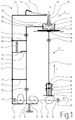
- the stapling device 1 is arranged on a known type of finisher unit not illustrated in which individually fed sheets, in particular copy sheets supplied by a copier, are collected in a stack in a collecting station 36 and combined in sets by means of staples.
- the stapling device is a comprehensive assembly unit of a design as described for example in DE-OS 40 20 355.
- Stapling device 1 substantially consists of a driver unit 2 and a clincher unit 3.
- Clincher unit 3 is actuated by a slider 4 and a leaf spring 37 attached to said slider.
- the driver unit 2, the clincher unit 3 and the slider 4 are actuated by control cams 11 and 12 and 13 respectively (which for better understanding are shown in Fig. 1 in a position in which they have been rotated by 90_ relative to their plane of operation).
- the control cams are connected to a shaft 10 mounted for rotation in bearings 22, 23 and driven by a motor in the direction of the arrow "A".
- the sheets 35 to be stapled are fed into a collecting station 36 where they are aligned with abutments not illustrated and collected in a stack in a manner known per se. At this point the driver unit 2 and the clincher unit 3 are sufficiently retracted to allow free passage of the incoming sheets.
- driver member 7 of driver unit 2 is shiftably mounted in guide means 17, 19 and supported at its lower end 7b by a pressure spring 9 arranged in a sleeve 8 which is shiftably guided in guide means 18, 38 and held in engagement with the third control cam 13.
- the upper end 7a of driver member 7 serves to drive the staples 34 into the collected sheet stack 35.
- the staples 34 to be driven in are formed in a manner known per se and not illustrated from a belt of wire sections supplied from a magazine not illustrated.
- the clincher unit 3 is arranged which is designed as an assembly group positioned on a holder 24.
- Holder 24 is attached to an upper arm 5a of a first slider 5 which is shiftably mounted in guide means 15, 16.
- a lower arm 5a of slider 5 is urged into contact with the second control cam 12 by a pressure spring 14.
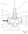
- holder 24 Fixed to holder 24 (see Fig. 2) is a guide sleeve 25 in which a two-part pushrod 26, 27 consisting of metal is shiftably mounted. Holder 24 and guide sleeve 25 are made of plastic. As shown in particular in Fig. 3, pushrod 26, 27 is a die-cast element composed of two identical portions which are positively connected by projections 26d and 27d respectively engaging oppositely arranged recesses 26e and 27e respectively.
- the pushrod portions 26 and 27 respectively have stepppd undercut mounting webs 26a and 27a respectively including mounting bores 26b and 27b respectively for mounting two identically designed rollers 28 and 29.
- the mounting webs 26a and 27a surround the rollers 28 and 29 in a forklike manner.
- the rollers 28 and 29 are provided with integrally formed journals 28a and 29a as well as with flanges 28b on either of their sides.
- the flanges 28b assist in the low-friction mounting of the rollers 28 and 29.
- the rollers 28 and 29 are made of hardened steel and are graphite-coated. The ratio of the diameters of the rollers 28, 29 to those of the journals 28a, 29a is 4: 1.
- Pushrod 26, 27 with its rollers 28, 29 is guided for movement vertically to the plane of the sheet stack and arranged symmetrically with respect to staple 34.
- the projections 26d, 27d and the recesses 26e, 27e of the pushrod portions 26 and 27 are designed such that the pushrod portions 26, 27 can be riveted to form a unit after the rollers 28, 29 have been inserted, with the rollers 28, 29 being capable of free rotation after such riveting.
- Two identically designed blade-shaped bending elements 30 and 31 of hardened steel are also arranged on holder 24 and mounted for rotation about journals 32, 33.
- the bending elements 30, 31 arranged in the longitudinal direction of staple 34 are mounted at one of their ends outside staple 34 (journal 32 and 33 respectively) and with their other ends extend within the inner space of staple 34.
- Each of the bending elements 30 and 31 respectively is associated with one end of a staple 34 driven through the sheet stack 35.
- the bending elements 30 and 31 are arranged symmetrically with respect to the position of the staple, movable towards and away from each other and positioned parallel and directly adjacent to each other.
- the bending elements 30 and 31 each have a convex curvature 30b and 31b respectively of an involute shape which is each contacted by a roller 28 and 29 respectively.
- the bending elements 30, 31 are each provided with a first surface section located adjacent to the journals 32 and 33 respectively and showing a concave curvature 30c, 31c. This section is followed by a section 30d, 31d each having a convex curvature and associated with the inner space of staple 34.
- the driver unit 2 is actuated by a second slider 4 which is slidably mounted in guide means 20 and 21 arranged on arms 5c, 5d of the first slider 5.
- a central arm 4e of the second slider 4 is influenced by a tension spring 6 which is attached to arm 5c of the first slider 5 such that arm 4e is spring-biased into contact with a projection 5e of the first slider 5.
- the second slider 4 has an upper and a lower arm 4a and 4d respectively.
- Mounted to a holder 4c of the upper arm 4a is a leaf spring 37 which extends with its free end over pushrod 26, 27 of the clincher unit 3.
- Leaf spring 37 is biased into contact with end 4b of the upper arm 4.
- the lower arm 4d of the second slider 4 engages the first control cam 11.
- Fig. 1 shows the device in an initial position in which holder 24 of clincher unit 3 is spaced from collecting station 36 such that incoming sheets can pass freely up to the aligning abutments not illustrated.
- shaft 10 is made to rotate by the drive not illustrated so that the control cams 11, 12 and 13 are rotated in the direction of the arrow "A ".
- the second control cam 12 causes the lower arm 5b of the first slider 5 to move downwards and the holder 24 of clincher unit 3 to move closer to sheet stack 35 without the stack being directly contacted.
- the control cams 12 and 13 are provided with concentric circular sections (not illustrated) which are brought into engagement if the control condition reached is to be continued.
- the first control cam 11 moves the second slider 4 downwards in opposition to the direction of the arrow "C" so that leaf spring 37 arranged at the upper arm 4a contacts pushrod 26, 27 and moves said rod downwards in the direction of the arrow "B” in opposition to the weak spring bias influencing the bending elements 30 and 31.
- This causes arm 4e of the second slider 4 to move away from projection 5e of the first slider 5 while tension spring 6 is tensioned.
- the rollers 28 and 29 pivot the bending elements 30 and 31 onto the upper surface of sheet stack 35.
- the concave curvatures 30c, 31c of the bending elements 30 and 31 bend the ends of staple 34 further inwardly before the ends are pressed against sheet stack 35 in a flat position by the convex surface sections 30d and 31d.
- rollers 28 and 29 respectively roll over the convex curvatures 30b and 31b respectively of the bending elements 30 and 31 respectively, rotating in opposite directions as indicated by the arrows in Fig. 2.
- continuously alternating contact points are brought into engagement during pivotal movement of the bending elements 30, 31. This prevents the drive of the bending elements 30, 31 from being inhibited by sliding friction.
- Leaf spring 37 is biased to such an extent that it continues to rest against the end 4b of slider arm 4a during the clinching of staple 34. Only when the ends of staple 34 rest on sheet stack 35 is leaf spring 37 lifted from the end 4b of slider arm 4a and thus allows the various movements to be compensated.
- control cams 11, 12 and 13 are further rotated in the same direction.
- the concentric section of the third control cam 13 moves out of contact with sleeve 8 so that pressure spring 9 is relieved and driver member 7 moves back in opposition to the direction of the arrow "C".
- control cams 11 and 12 When driver member 7 is returned the control cams 11 and 12 also change their positions, which causes the first slider 5 to move, under the action of pressure spring 14, to its upper position in which holder 24 of clincher unit 3 once again assumes its raised initial position. Rotation of the first control cam 11 moreover causes the pre-tensioned tension spring 6 to pull the second slider 4 upwards in the direction of the arrow "C" until its arm 4e rests against projection 5e and slider 4 once again assumes its initial position in which it is shown in Fig. 1.
- rollers 28, 29 In contrast to this automatically effective continuous rotation of the rollers 28, 29, such rotary movement can also be directionally constrained if the prevailing pressure conditions call for such a type of control.
- the rollers 28, 29 need just be associated with a backstop so that they are rotated as described during each working stroke while being prevented from rotation during the return stroke of pushrod 26, 27. This, too, ensures a uniform load distribution over the circumference of the rollers 28, 29.
- a backstop 39 of the type illustrated in Figs. 5 and 6 is arranged between the rollers 28, 29 and one of the mounting webs 26a or 27a of pushrod 26, 27.
- Backstop 39 is plugged onto the two journals 28a and 29a and includes two resilient locking arms 39a and 39b cooperating with recesses 28c and 29c respectively of the rollers 28 and 29 respectively.
- each of the rollers 28 and 29 has one of its flanks provided with a plurality of recesses 28c and 29c respectively concentrically spaced at equal distances about the journals 28a, 29a.
- the resilient locking arms 39a and 39b respectively are symmetrically arranged with respect to a center of backstop 39, which is located centrally between the journals 28a and 29a.
- the locking arms 39a, 39b of equal lengths which are arranged in parallel with a line connecting the axes of rotation of the journals 28a, 29a are each bent towards the flanks of the rollers and slightly biased such that they can be brought into engagement with the recesses 28c and 29c respectively.
- the ends of the locking arms 39a and 39b engaging the recesses 28c and 29c respectively are suitably shaped (rounded) and provided with surfaces (level) ensuring low-friction operation.
- rollers 28, 29 may also be mounted side by side for idle movement about a shaft (not illustrated) if the bending elements 30, 31 are long enough to pass below the common axis of rotation.
- the contact flanks of such adjacently arranged rollers are preferably separated from each other by an idly rotating washer in order to facilitate rotating of the rollers in opposite directions.
Landscapes
- Engineering & Computer Science (AREA)
- Textile Engineering (AREA)
- Folding Of Thin Sheet-Like Materials, Special Discharging Devices, And Others (AREA)
- Dovetailed Work, And Nailing Machines And Stapling Machines For Wood (AREA)
Applications Claiming Priority (2)
| Application Number | Priority Date | Filing Date | Title |
|---|---|---|---|
| DE4303503 | 1993-02-06 | ||
| DE4303503A DE4303503A1 (de) | 1993-02-06 | 1993-02-06 | Heftvorrichtung zum Zusammenheften von Blättern |
Publications (1)
| Publication Number | Publication Date |
|---|---|
| EP0610799A1 true EP0610799A1 (fr) | 1994-08-17 |
Family
ID=6479818
Family Applications (1)
| Application Number | Title | Priority Date | Filing Date |
|---|---|---|---|
| EP94101581A Withdrawn EP0610799A1 (fr) | 1993-02-06 | 1994-02-03 | Machine pour agrafage de feuilles |
Country Status (4)
| Country | Link |
|---|---|
| US (1) | US5385287A (fr) |
| EP (1) | EP0610799A1 (fr) |
| JP (1) | JPH06315904A (fr) |
| DE (1) | DE4303503A1 (fr) |
Families Citing this family (7)
| Publication number | Priority date | Publication date | Assignee | Title |
|---|---|---|---|---|
| DE19607296A1 (de) * | 1996-02-27 | 1997-08-28 | Kodak Ag | Heftvorrichtung zum Zusammenheften von Blättern |
| JP4644973B2 (ja) | 2000-06-01 | 2011-03-09 | マックス株式会社 | 電動ステープラ |
| GB2376912B (en) * | 2001-06-27 | 2003-04-09 | Isaberg Rapid Ab | Clinching mechanism for staplers |
| JP4232371B2 (ja) * | 2002-01-11 | 2009-03-04 | マックス株式会社 | ステープラー |
| DE602005019972D1 (de) * | 2004-01-13 | 2010-04-29 | Max Co Ltd | Klammermaschine |
| US20070023474A1 (en) * | 2005-07-14 | 2007-02-01 | Smith Robert S | Clincher for a heavy duty stapler |
| US9192377B1 (en) * | 2009-06-02 | 2015-11-24 | Cardica, Inc. | Work hardening of staples within surgical stapler |
Citations (5)
| Publication number | Priority date | Publication date | Assignee | Title |
|---|---|---|---|---|
| EP0009964A1 (fr) * | 1978-10-02 | 1980-04-16 | Xerox Corporation | Appareil pour relier un jeu d'articles par agrafage |
| EP0051395A2 (fr) * | 1980-11-03 | 1982-05-12 | Xerox Corporation | Dispositif de repliage et appareil à agrafer muni d'un tel dispositif |
| US4593847A (en) * | 1985-05-01 | 1986-06-10 | Interlake, Inc. | Bypass clincher for stitching machine |
| EP0266700A2 (fr) * | 1986-10-31 | 1988-05-11 | Max Co., Ltd. | Dispositif pour la coupe des jambes d'une agrafe |
| WO1990008015A1 (fr) * | 1989-01-23 | 1990-07-26 | Swingline Inc. | Enclume de guidage comprenant des ailes de rabattage mobiles pour agrafeuse |
Family Cites Families (9)
| Publication number | Priority date | Publication date | Assignee | Title |
|---|---|---|---|---|
| DE96433C (fr) * | ||||
| US2585807A (en) * | 1950-04-12 | 1952-02-12 | Jr James G Mackechnie | Wire stitching apparatus |
| DE1189562B (de) * | 1962-01-10 | 1965-03-25 | Albert Schnellpressen | Einrichtung an einem Heftapparat von Rotationsdruckmaschinen zum selbsttaetigen Formen der Heftklammern |
| DD96433A1 (fr) * | 1972-05-05 | 1973-03-20 | ||
| US3986533A (en) * | 1975-11-26 | 1976-10-19 | Usm Corporation | Mechanism for clinching leads inwardly or outwardly |
| MX149500A (es) * | 1978-12-29 | 1983-11-15 | Xerox Corp | Mejoras en cosedoras de alambre para encuadernar conjuntos de hojas |
| US4546910A (en) * | 1982-07-07 | 1985-10-15 | Xerox Corporation | Active clinchers and wire stitchers incorporating same |
| DE4020355C2 (de) * | 1990-06-27 | 1996-02-29 | Kodak Ag | Heftvorrichtung zum Zusammenheften von Blättern |
| DE59203754D1 (de) * | 1991-12-13 | 1995-10-26 | Ferag Ag | Vorrichtung zum Drahtheften von mehrteiligen Druckereierzeugnissen. |
-
1993
- 1993-02-06 DE DE4303503A patent/DE4303503A1/de not_active Withdrawn
-
1994
- 1994-01-14 US US08/181,933 patent/US5385287A/en not_active Expired - Fee Related
- 1994-02-03 EP EP94101581A patent/EP0610799A1/fr not_active Withdrawn
- 1994-02-04 JP JP6012862A patent/JPH06315904A/ja active Pending
Patent Citations (5)
| Publication number | Priority date | Publication date | Assignee | Title |
|---|---|---|---|---|
| EP0009964A1 (fr) * | 1978-10-02 | 1980-04-16 | Xerox Corporation | Appareil pour relier un jeu d'articles par agrafage |
| EP0051395A2 (fr) * | 1980-11-03 | 1982-05-12 | Xerox Corporation | Dispositif de repliage et appareil à agrafer muni d'un tel dispositif |
| US4593847A (en) * | 1985-05-01 | 1986-06-10 | Interlake, Inc. | Bypass clincher for stitching machine |
| EP0266700A2 (fr) * | 1986-10-31 | 1988-05-11 | Max Co., Ltd. | Dispositif pour la coupe des jambes d'une agrafe |
| WO1990008015A1 (fr) * | 1989-01-23 | 1990-07-26 | Swingline Inc. | Enclume de guidage comprenant des ailes de rabattage mobiles pour agrafeuse |
Also Published As
| Publication number | Publication date |
|---|---|
| JPH06315904A (ja) | 1994-11-15 |
| DE4303503A1 (de) | 1994-08-11 |
| US5385287A (en) | 1995-01-31 |
Similar Documents
| Publication | Publication Date | Title |
|---|---|---|
| US5799935A (en) | Automatic stapling device | |
| CA1188451A (fr) | Dispositif de mise en forme et de pose d'agrafes | |
| US5385287A (en) | Sheet-stapling device | |
| US5141143A (en) | Sheet-stapling device | |
| EP0099249B1 (fr) | Dispositif d'agrafage à fil métallique perfectionné | |
| US20090000900A1 (en) | Clutch with adjusting device | |
| US8348121B2 (en) | Stapler | |
| US6916281B2 (en) | Method and apparatus for sheet folding | |
| US6820787B2 (en) | Stapler | |
| US4510841A (en) | Mechanism for cutting single thickness paper or like sheet material and apparatus including such mechanism | |
| US5862971A (en) | Stapling apparatus | |
| JPH0689821A (ja) | 負荷時タップ切換変圧器のタップ切換装置用の負荷開閉器 | |
| US6641024B2 (en) | Stapling device | |
| EP0920963B1 (fr) | Dispositif d'agrafage | |
| CA1161201A (fr) | Agrafeuse a force de penetration amelioree | |
| US20250001642A1 (en) | Stapler | |
| JPH11216687A (ja) | ステープル装置 | |
| JPH05147808A (ja) | 個別にスタツクへ供給されるシートを堆積させかつ整合させる装置 | |
| JP2002540042A (ja) | 接着テープストリップ分配器 | |
| US2033049A (en) | Stapling device | |
| EP0266139B2 (fr) | Mécanisme d'actionnement de rouleaux presseurs pour une imprimante | |
| US5582340A (en) | Drive mechanism in a stapler | |
| JP6210137B1 (ja) | 綴じ装置および画像処理装置 | |
| JP4675687B2 (ja) | リミットスイッチ | |
| JPH0554833U (ja) | 波形ばね |
Legal Events
| Date | Code | Title | Description |
|---|---|---|---|
| PUAI | Public reference made under article 153(3) epc to a published international application that has entered the european phase |
Free format text: ORIGINAL CODE: 0009012 |
|
| AK | Designated contracting states |
Kind code of ref document: A1 Designated state(s): DE FR GB |
|
| STAA | Information on the status of an ep patent application or granted ep patent |
Free format text: STATUS: THE APPLICATION HAS BEEN WITHDRAWN |
|
| 18W | Application withdrawn |
Withdrawal date: 19950119 |
|
| R18W | Application withdrawn (corrected) |
Effective date: 19950119 |