EP0611002A1 - Elément d'assemblage démontable rapide en particulier pour meubles - Google Patents
Elément d'assemblage démontable rapide en particulier pour meubles Download PDFInfo
- Publication number
- EP0611002A1 EP0611002A1 EP94200300A EP94200300A EP0611002A1 EP 0611002 A1 EP0611002 A1 EP 0611002A1 EP 94200300 A EP94200300 A EP 94200300A EP 94200300 A EP94200300 A EP 94200300A EP 0611002 A1 EP0611002 A1 EP 0611002A1
- Authority
- EP
- European Patent Office
- Prior art keywords
- dowel
- seat
- fastener
- accordance
- anchor
- Prior art date
- Legal status (The legal status is an assumption and is not a legal conclusion. Google has not performed a legal analysis and makes no representation as to the accuracy of the status listed.)
- Granted
Links
- 230000037431 insertion Effects 0.000 claims abstract description 20
- 238000003780 insertion Methods 0.000 claims abstract description 20
- 239000000463 material Substances 0.000 claims description 4
- 238000003475 lamination Methods 0.000 description 5
- 238000005452 bending Methods 0.000 description 2
- 230000000295 complement effect Effects 0.000 description 2
- 230000000694 effects Effects 0.000 description 2
- 230000035515 penetration Effects 0.000 description 2
- 239000013013 elastic material Substances 0.000 description 1
- 238000000605 extraction Methods 0.000 description 1
- 238000009434 installation Methods 0.000 description 1
- 238000003754 machining Methods 0.000 description 1
- 230000014759 maintenance of location Effects 0.000 description 1
- 230000007246 mechanism Effects 0.000 description 1
- 239000002184 metal Substances 0.000 description 1
- 239000002023 wood Substances 0.000 description 1
Images


Classifications
-
- F—MECHANICAL ENGINEERING; LIGHTING; HEATING; WEAPONS; BLASTING
- F16—ENGINEERING ELEMENTS AND UNITS; GENERAL MEASURES FOR PRODUCING AND MAINTAINING EFFECTIVE FUNCTIONING OF MACHINES OR INSTALLATIONS; THERMAL INSULATION IN GENERAL
- F16B—DEVICES FOR FASTENING OR SECURING CONSTRUCTIONAL ELEMENTS OR MACHINE PARTS TOGETHER, e.g. NAILS, BOLTS, CIRCLIPS, CLAMPS, CLIPS OR WEDGES; JOINTS OR JOINTING
- F16B12/00—Jointing of furniture or the like, e.g. hidden from exterior
- F16B12/10—Jointing of furniture or the like, e.g. hidden from exterior using pegs, bolts, tenons, clamps, clips, or the like
- F16B12/12—Jointing of furniture or the like, e.g. hidden from exterior using pegs, bolts, tenons, clamps, clips, or the like for non-metal furniture parts, e.g. made of wood, of plastics
- F16B12/24—Jointing of furniture or the like, e.g. hidden from exterior using pegs, bolts, tenons, clamps, clips, or the like for non-metal furniture parts, e.g. made of wood, of plastics using separate pins, dowels, or the like
-
- F—MECHANICAL ENGINEERING; LIGHTING; HEATING; WEAPONS; BLASTING
- F16—ENGINEERING ELEMENTS AND UNITS; GENERAL MEASURES FOR PRODUCING AND MAINTAINING EFFECTIVE FUNCTIONING OF MACHINES OR INSTALLATIONS; THERMAL INSULATION IN GENERAL
- F16B—DEVICES FOR FASTENING OR SECURING CONSTRUCTIONAL ELEMENTS OR MACHINE PARTS TOGETHER, e.g. NAILS, BOLTS, CIRCLIPS, CLAMPS, CLIPS OR WEDGES; JOINTS OR JOINTING
- F16B17/00—Connecting constructional elements or machine parts by a part of or on one member entering a hole in the other and involving plastic deformation
-
- F—MECHANICAL ENGINEERING; LIGHTING; HEATING; WEAPONS; BLASTING
- F16—ENGINEERING ELEMENTS AND UNITS; GENERAL MEASURES FOR PRODUCING AND MAINTAINING EFFECTIVE FUNCTIONING OF MACHINES OR INSTALLATIONS; THERMAL INSULATION IN GENERAL
- F16B—DEVICES FOR FASTENING OR SECURING CONSTRUCTIONAL ELEMENTS OR MACHINE PARTS TOGETHER, e.g. NAILS, BOLTS, CIRCLIPS, CLAMPS, CLIPS OR WEDGES; JOINTS OR JOINTING
- F16B12/00—Jointing of furniture or the like, e.g. hidden from exterior
- F16B12/10—Jointing of furniture or the like, e.g. hidden from exterior using pegs, bolts, tenons, clamps, clips, or the like
- F16B12/12—Jointing of furniture or the like, e.g. hidden from exterior using pegs, bolts, tenons, clamps, clips, or the like for non-metal furniture parts, e.g. made of wood, of plastics
- F16B12/20—Jointing of furniture or the like, e.g. hidden from exterior using pegs, bolts, tenons, clamps, clips, or the like for non-metal furniture parts, e.g. made of wood, of plastics using clamps, clips, wedges, sliding bolts, or the like
-
- A—HUMAN NECESSITIES
- A47—FURNITURE; DOMESTIC ARTICLES OR APPLIANCES; COFFEE MILLS; SPICE MILLS; SUCTION CLEANERS IN GENERAL
- A47B—TABLES; DESKS; OFFICE FURNITURE; CABINETS; DRAWERS; GENERAL DETAILS OF FURNITURE
- A47B2230/00—Furniture jointing; Furniture with such jointing
- A47B2230/0029—Dowels
- A47B2230/0044—Fastening elements comprising radially expansible plugs by rotation therein of inserted pins
-
- A—HUMAN NECESSITIES
- A47—FURNITURE; DOMESTIC ARTICLES OR APPLIANCES; COFFEE MILLS; SPICE MILLS; SUCTION CLEANERS IN GENERAL
- A47B—TABLES; DESKS; OFFICE FURNITURE; CABINETS; DRAWERS; GENERAL DETAILS OF FURNITURE
- A47B2230/00—Furniture jointing; Furniture with such jointing
- A47B2230/11—Attachment fittings mounted in blind holes
Definitions
- the present invention relates to fasteners for snap fastening and in particular for fastening furniture hardware elements such as hinges, drawer slides, etc.
- fasteners comprising dowel anchors to be engaged in holes in furniture panels while in said dowel anchors there being subsequently engageable fastening screws for hinges, slides, etc.
- the general purpose of the present invention is to supply economical fasteners permitting fast assembly and allowing at the same time easy disassembly without the need of special tools or skills on the part of the installer.
- a removable fastener for a part such as a furniture accessory with a surface hole comprising a dowel anchor with means of lateral engagement in the surface hole and the dowel anchor comprising a seat in which is received the end of a dowel in turn constrained to the part and between the element and the seat there being present separable mutual constraint means and characterised in that the element is provided in the form of a dowel constrained to the part to be axially insertable in the seat in the dowel anchor and the constraint means comprising elastic yielding elements projecting in the seat to engage on opposite sides of the dowel.
- Fig. 1 shows a first fastener or joint in accordance with the present invention indicated generally by reference number 10.
- the joint 10 comprises a dowel anchor 11 pressed from relatively yielding material and in which engages a connecting dowel 12.
- the dowel 12 has a generally cylindrical form with one end bearing an enlarged handling head 21, e.g. provided with a screwdriver notch. Near the other end, the side surface of the dowel has two notches 26, 27 arranged in a mutually symmetrically manner.
- the insertion end of the dowel can advantageously have a taper 22 to facilitate insertion.
- the dowel 11 has an axial hole 13 for reception with minimal side play of the dowel 12.
- the mouth 16 of the hole can have a flaring to facilitate insertion of the dowel.
- In the hole 13 projects a pair of facing tabs 14, 15 with free ends directed toward each other and in the direction opposite the opening 16 for insertion of the dowel 12 in the hole 13.
- the notches has smaller diameter than the seat or hole 13.
- the steps 19, 20 with facing surfaces which receive with minimal side play the part of the cylindrical dowel with smaller diameter so that the dowel is supported for its entire length.
- the dowel anchor 11 has advantageously a cylindrical form coaxial with the hole 13 and an external side surface with ribbing 23 constituting as clarified below means of engagement of the dowel anchor in a suitable hole in the assembly surface.
- the ribbings 23 can be circumferential ribbings shaped like an arrow in the direction of insertion of the dowel in the anchor.
- Figs. 4 and 5 is shown a possible employment of the above described joint to fasten to a surface 24 a hardware element 25.
- the surface 24 can be e.g. a wood panel providing a shoulder or a drawer compartment of a furniture item and the hardware element can consequently be a guide for the drawers.
- the dowel anchor 11 is inserted, e.g. by pressure, in a complementary hole made in the surface 24.
- the retention means 23 prevent removal of the dowel anchor.
- In the dowel anchor can then be inserted by snapping the dowel 12 after it has been passed through a fastening hole of the element 25.
- the yielding tabs 14, 15 snap out at the notches 26, 27.
- the free ends of the tabs engage against the striker surface formed by the wall of the notches and the arrow arrangement of the tabs blocks the dowel to prevent is removal.
- the presence of the dowel 12 in the hole 13 also makes the engagement between the dowel anchor and the panel 24 stronger while supplying a slight expansion of the dowel anchor which is compressed during insertion in the complementary hole in the panel. To disassemble the joint it suffices to rotate the dowel 12 90° so as to bring its cylindrical surface in alignment with the tabs.
- the dowel head will be formed in accordance with the requirements of the piece to be fastened. For example, if it is required that the head remain flush with the surface of the fastened piece a dowel with a tapered head can be provided as shown in Figs. 1 to 5.
- Fig. 6 shows a dowel 12' with projecting head, e.g. to fasten a known cup element 28 of a furniture hinge.
- the dowel head has a radial projection 29 which interferes with two teeth 30, 31 projecting from the surface of the cup at the sides of the hole where the dowel passes.
- the size of the projection and the position of the teeth are such as to permit axial rotation of the dowel between an engagement position for the notches with the tabs and a disengagement position rotated 90°.
- the dowel 12' can advantageously have a circumferential groove 32 near the head so as to receive a bent edge 33 of the hole passing through the element 28 to be fastened. In this manner the dowel is free to rotate but remains axially constrained to the element to be fastened thus speeding up assembly.
- the head of the dowel can also have different means of gripping for handling thereof and not necessarily a notch for a blade or cross screwdriver.
- a notch for a blade or cross screwdriver For example, there can be provided an engagement for a hexagonal wrench or projections for manual handling without tools.
- the dowel anchor can have an edge 37 projecting circumferentially to the insertion end of the dowel to prevent excessive penetration of the dowel anchor in the engagement surface.
- FIG. 8 shows an engagement pin 12'' provided in two parts.
- a first part 34 has a form similar to that of the legs of the dowels described above while a second part 35 consists of a screw which screws into a threaded hole axial with the stem 34. It is thus easy to place between the screw and the stem an element 36 to be fastened.
- the thread of the screw can be provided of a length such as to permit mutual locking between the screw and the stem without preventing their rotation in the passing hole in the element 36.
- the radial elastic engagement means of the dowel can be provided in a different manner from elastic tabs 14, 15 in a single piece with the dowel anchor.
- Figs. 9, 10 and 11 show a possible variation in which the dowel anchor 11' has two notches 38, 39 parallel to each other and arranged to intersect the passing hole of the dowel on both sides of its symmetry axis.
- Two laminations 40, 41 are provided with free ends bent back and are inserted in the two passages 38, 39 so as to pass with their central part in the dowel hole clear space.
- the dowel anchor need not be of elastic material.
- the lamination means 40, 41 need not consist of a flat lamination but can be in the form of a piano wire with round section.
- the dowel 42 is shown with the stem longer than the seat in the dowel anchor to permit e.g. fastening of elements which are thick or furnish a side surface like a cam for known closing mechanisms.
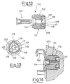
- Fig. 12 shows a further dowel anchor joint element in accordance with the present invention and indicated generically by reference number 110 comprises a dowel anchor body 111 provided in relatively yielding material, e.g. plastic.
- the dowel anchor 111 has a substantially cylindrical shape with circumferential ribbings 112 of generally triangular cross section and tapered in the direction of insertion of the dowel anchor in a hole or reception seat.
- the dowel anchor 111 has an axial hole for reception of a dowel 114 with widened head.
- the bottom of the hole 113 terminates in a widened seat 115 in which is inserted an elastic washer 116.
- an elastic washer 116 As may be seen also in Fig.
- the washer 116 is shaped with a plurality of teeth or tabs 117 directed radially toward the axis of the hole 113 and appropriately inclined in the direction of insertion of the dowel 114 in the hole 113.
- the teeth delimit with their endS a passage with dimensions slightly less than the diameter of the dowel.
- the dowel 111 when in use the dowel 111 is inserted by pressure inside a hole made in the fastening surface 120, e.g. a wall or a door of a furniture item.
- the stem of the dowel is passed through a hole provided for that purpose in the hardware element or part 122 which it is wished to constrain to the surface 120 and then engaged by force in the hole 113.
- the slight forcing of the dowel on the edges of the washer teeth cause the teeth to bend slightly without exerting excessive resistance to complete introduction of the dowel.
- Axial withdrawal of the dowel is prevented by the digging effect resulting from the angle formed by the teeth with the axis of the dowel.
- the dowel locks in the dowel anchor as described above but can be easily removed by rotating it with a screwdriver.
- the dowel head is cut.
- extraction can be aided by a slight axial traction during rotation.
- the teeth 117 can be provided inclined so that their ends form a screw in such a manner that the rotary movement of the dowel pushes it in an axial direction.
- the bottom of the cavity 115 can be advantageously provided in tapered form. This prevents the teeth from straightening beyond the taper angle of the bottom on which the washer rests.
- the washer e.g. pressed from sheet metal, can advantageously comprise peripherally projections or tabs 118 which engage in corresponding seats 119 in the dowel anchor to prevent rotation thereof with the rotating dowel.
- the proportions of the various parts can vary depending on the specific requirements of use.
- disassembly capability is not required in embodiment show in Fig. 12, helical machining of the teeth can be avoided.
- the washer can also be incorporated in the dowel anchor during a pressing phase of said dowel anchor.
Landscapes
- Engineering & Computer Science (AREA)
- General Engineering & Computer Science (AREA)
- Mechanical Engineering (AREA)
- Dowels (AREA)
- Furniture Connections (AREA)
- Snaps, Bayonet Connections, Set Pins, And Snap Rings (AREA)
- Connection Of Plates (AREA)
- Adornments (AREA)
Applications Claiming Priority (4)
| Application Number | Priority Date | Filing Date | Title |
|---|---|---|---|
| ITMI930113U | 1993-02-11 | ||
| IT93MI000113U IT229635Y1 (it) | 1993-02-11 | 1993-02-11 | Dispositivo di fissaggio rapido e rimuovibile in particolare per mobili |
| ITMI930878 IT230490Y1 (it) | 1993-11-12 | 1993-11-12 | Innesto rapido a tassello |
| ITMI930878U | 1993-11-12 |
Publications (2)
| Publication Number | Publication Date |
|---|---|
| EP0611002A1 true EP0611002A1 (fr) | 1994-08-17 |
| EP0611002B1 EP0611002B1 (fr) | 1998-07-08 |
Family
ID=26330950
Family Applications (1)
| Application Number | Title | Priority Date | Filing Date |
|---|---|---|---|
| EP94200300A Expired - Lifetime EP0611002B1 (fr) | 1993-02-11 | 1994-02-03 | Elément d'assemblage démontable rapide en particulier pour meubles |
Country Status (9)
| Country | Link |
|---|---|
| US (1) | US5468109A (fr) |
| EP (1) | EP0611002B1 (fr) |
| JP (1) | JPH06341414A (fr) |
| KR (1) | KR940020009A (fr) |
| AT (1) | ATE168170T1 (fr) |
| BR (1) | BR9400469A (fr) |
| CA (1) | CA2114999A1 (fr) |
| DE (1) | DE69411410T2 (fr) |
| ES (1) | ES2118308T3 (fr) |
Cited By (10)
| Publication number | Priority date | Publication date | Assignee | Title |
|---|---|---|---|---|
| WO1999041508A3 (fr) * | 1998-02-11 | 1999-09-23 | Ipeg Unabhaengige Immobilienbe | Dispositif d'assemblage pour corps plats ou autres composants |
| ES2141037A1 (es) * | 1998-01-26 | 2000-03-01 | Euro Seating Int Sa | Dispositivo de anclaje de butacas y/o similares. |
| EP1148256A2 (fr) | 2000-01-26 | 2001-10-24 | IPEG GmbH, Ingenieurdienstleistungen | Assemblage pour joint de serrage/pression en tension, détachable, en particulier pour deux panneaux |
| EP1213495A3 (fr) * | 2000-12-07 | 2003-05-07 | Schwarz Verbindungs-Systeme GmbH | Montage de ressort à lame et dispositif de fixation pour le raccordement démontable de deux éléments |
| US6901646B2 (en) * | 2002-01-16 | 2005-06-07 | Avaya Technology Corp. | Universal snap-fit spacer |
| FR2905151A1 (fr) * | 2006-08-23 | 2008-02-29 | Peugeot Citroen Automobiles Sa | Dispositif de fixation d'une premiere piece formant piece de support a une seconde piece a l'aide d'un moyen de fixation par clippage |
| WO2008104256A1 (fr) * | 2007-02-26 | 2008-09-04 | MEPLA-WERKE LAUTENSCHLäGER GMBH & CO. KG | Ferrure |
| WO2010005911A3 (fr) * | 2008-07-07 | 2010-08-26 | Fin Quiver, Inc. | Mécanisme de verrouillage relâchable |
| WO2014072080A1 (fr) * | 2012-11-06 | 2014-05-15 | Inter Ikea Systems B.V. | Dispositif de fixation, système de fixation et ensemble meuble |
| US9090318B2 (en) | 2006-01-20 | 2015-07-28 | Lockdowel, Inc. | Latching system |
Families Citing this family (43)
| Publication number | Priority date | Publication date | Assignee | Title |
|---|---|---|---|---|
| IT233517Y1 (it) * | 1994-06-21 | 2000-01-28 | Ferrari Franco | Assieme di vincolo a tassello con regolazione della posizione per elementi di ferramenta in particolare guide per cassetti |
| JP3297972B2 (ja) * | 1995-04-17 | 2002-07-02 | 株式会社パイオラックス | 固定クリップ |
| US5754412A (en) * | 1995-10-04 | 1998-05-19 | Hartwell Corporation | Circuit board standoff connector |
| DE19541180A1 (de) * | 1995-11-04 | 1997-05-07 | Mst Automotive Gmbh | Mittel zur Befestigung eines Airbag-Moduls |
| JPH10210716A (ja) * | 1997-01-24 | 1998-08-07 | Mitsuba Corp | 締め具インサート構造物 |
| US6079920A (en) * | 1999-02-09 | 2000-06-27 | Lucent Technologies Inc. | Captive fastener |
| US6464423B1 (en) * | 1999-02-23 | 2002-10-15 | Bretford Manufacturing, Inc. | Ganging bracket |
| EP1222490B1 (fr) * | 1999-10-21 | 2009-03-18 | Lindberg A/S | Paire de lunettes et procede de fabrication associe |
| US6464214B1 (en) * | 2000-09-07 | 2002-10-15 | Paulstra Crc | Anti-vibration mounting for clip-fit connection means and vehicle fitted with this mounting |
| KR20030017724A (ko) * | 2001-08-22 | 2003-03-04 | 기아자동차주식회사 | 자동차용 파스너구조 |
| US7345235B2 (en) * | 2004-03-17 | 2008-03-18 | Yamaha Corporation | Keyboard musical instrument having keys equipped with balancers biting into keys and method for securing balancers to keys |
| TWI286736B (en) * | 2005-03-15 | 2007-09-11 | Yamaha Corp | Movable part firmly equipped with balance weight, musical instrument and method of assembling balance weight therein |
| US20080031702A1 (en) * | 2006-08-01 | 2008-02-07 | Ken-Ching Chen | Fast nail plug |
| CN100523525C (zh) * | 2006-08-03 | 2009-08-05 | 川湖科技股份有限公司 | 快速钉套固定装置 |
| TWI391571B (zh) * | 2009-04-03 | 2013-04-01 | Ship & Ocean Ind R & D Ct | Quick assembly of the board with the buckle device |
| TWI392805B (zh) * | 2009-05-25 | 2013-04-11 | Au Optronics Suzhou Corp | 固定結構及具有該固定結構之顯示裝置 |
| US8137039B2 (en) * | 2009-08-06 | 2012-03-20 | King Slide Works Co., Ltd. | Connecting fitting |
| DE102009059327A1 (de) * | 2009-12-30 | 2011-07-07 | Franz Schneider Brakel GmbH & Co. KG, 33034 | Beschlag für Türen oder Fenster |
| JP2011231835A (ja) * | 2010-04-27 | 2011-11-17 | Sumitomo Wiring Syst Ltd | 溝付棒状部材用のクランプ及びワイヤーハーネス用プロテクタ |
| KR101064770B1 (ko) * | 2010-04-29 | 2011-09-14 | 장근대 | 앵커축 및 이의 제조방법 |
| US20110311335A1 (en) * | 2010-06-21 | 2011-12-22 | Douglas Wike | Removable fastener |
| JP6436282B2 (ja) * | 2013-04-23 | 2018-12-12 | ファストマウント リミテッドFastmount Limited | コネクタ組立体およびコネクタ組立体用の部品のキット |
| JP5719485B1 (ja) * | 2013-07-31 | 2015-05-20 | 株式会社白井産業 | 部材の結合構造及びこれを備えた組立構造物 |
| WO2015015603A1 (fr) * | 2013-07-31 | 2015-02-05 | 株式会社白井産業 | Structure de couplage d'élément, et structure d'assemblage la comportant |
| DE202014105730U1 (de) * | 2014-11-27 | 2016-03-02 | Grass Gmbh & Co. Kg | Wandelement eines Möbels und Möbel mit einem solchen Wandelement |
| SE540554C2 (en) * | 2015-12-16 | 2018-10-02 | Ikea Supply Ag | Attachment arrangement and piece of furniture |
| WO2018061013A1 (fr) * | 2016-10-01 | 2018-04-05 | Yaffe Aharon | Douille pour élément de fixation et blocs d'assemblage comprenant celle-ci |
| CN106523507B (zh) * | 2016-12-02 | 2019-03-29 | 江西洪都航空工业集团有限责任公司 | 一种螺栓防松装置 |
| CN106481641A (zh) * | 2016-12-23 | 2017-03-08 | 宁波引钲信息咨询有限公司 | 固定装置的结构 |
| US10722029B2 (en) * | 2017-04-20 | 2020-07-28 | David O. Boone Revocable Trust | Framed full access cabinet |
| FI129174B (en) * | 2017-09-21 | 2021-08-31 | Aito Products Oy | Shelf support and arrangements |
| GB2571082B (en) * | 2018-02-14 | 2022-05-18 | Intelligent Fixings Ltd | Joint structures |
| CN108591205B (zh) * | 2018-04-23 | 2024-10-22 | 深圳市优拓智能科技有限公司 | 板式家具隐形快速连接方法 |
| CN109854590B (zh) * | 2018-11-27 | 2024-10-22 | 佛山市爱拼科技有限公司 | 一种连接结构以及采用连接结构的板件组件 |
| US10920816B2 (en) * | 2018-12-05 | 2021-02-16 | Jeff Ellis | Furniture snap connector |
| CN111345634A (zh) * | 2018-12-21 | 2020-06-30 | 秦皇岛康姿百德地磁技术开发有限公司 | 一种家具软包装置及其使用方法 |
| EP3770448A1 (fr) * | 2019-07-23 | 2021-01-27 | Lercher GmbH | Système de liaison pour la liaison mécanique de deux matériaux |
| US11466715B2 (en) | 2020-06-02 | 2022-10-11 | Lear Corporation | Connector assembly |
| CN112922943B (zh) * | 2021-02-27 | 2023-03-21 | 广东精诺五金实业有限公司 | 一种连接装置 |
| GB2611069B (en) * | 2021-09-24 | 2024-01-17 | Ovvotech Innovations Ltd | A connector assembly |
| CN114165509B (zh) * | 2022-01-18 | 2023-05-23 | 北京安达维尔航空设备有限公司 | 一种用于飞机内饰板安装的弹簧插销结构 |
| US20230417269A1 (en) * | 2022-06-28 | 2023-12-28 | Illinois Tool Works Inc. | Quarter Turn Fastener |
| KR102617433B1 (ko) * | 2023-08-22 | 2023-12-28 | 윤성필 | 가구 조립용 원터치형 연결구 |
Citations (4)
| Publication number | Priority date | Publication date | Assignee | Title |
|---|---|---|---|---|
| DE1903025A1 (de) * | 1969-01-22 | 1970-08-06 | Mathias Kutsch | Vorrichtung zum Anbringen von Befestigungselementen an Schaumstoffkoerpern |
| AT351394B (de) * | 1973-06-01 | 1979-07-25 | Blum Gmbh Julius | Montageplatte mit einem elastischen duebel, und einem spreizteil |
| FR2506865A1 (fr) * | 1981-05-29 | 1982-12-03 | Rhein Louis | Ferrure d'assemblage invisible reglable a fixation instantanee |
| DE8717482U1 (de) * | 1987-07-07 | 1988-12-08 | Arturo Salice S.P.A., Novedrate, Como | Befestigungselement mit einer dübelartigen Buchse |
Family Cites Families (9)
| Publication number | Priority date | Publication date | Assignee | Title |
|---|---|---|---|---|
| US2252286A (en) * | 1939-09-14 | 1941-08-12 | Curtiss Wright Corp | Cowl fastener |
| US2337483A (en) * | 1942-07-10 | 1943-12-21 | Mathew J Marty | Fastening device |
| US2552066A (en) * | 1944-10-12 | 1951-05-08 | Glenn L Martin Co | Fastening device |
| GB588886A (en) * | 1945-03-09 | 1947-06-05 | Oddie Bradbury & Cull Ltd | Improvements in or relating to quick release cowling and like fasteners |
| US2936501A (en) * | 1954-10-13 | 1960-05-17 | Harold E Koch | Fastening device |
| CH595565A5 (en) * | 1974-11-25 | 1978-02-15 | Agfa Gevaert Ag | Snap type locking device with pin |
| US4275263A (en) * | 1979-08-03 | 1981-06-23 | The United States Of America As Represented By The Secretary Of The Air Force | Electrically insulating structurally strong bushing assembly |
| GB2195390A (en) * | 1986-09-26 | 1988-04-07 | Taiwan Ind Fastener Corp | Self-engaging securement foot |
| JPH05255895A (ja) * | 1992-03-10 | 1993-10-05 | Tokyo Multi Fastener Kk | ナット付き板金部品の製造方法並びに該方法の実施に使用するナット及びボルト・ナット・アッセンブリ |
-
1994
- 1994-02-01 US US08/189,882 patent/US5468109A/en not_active Expired - Fee Related
- 1994-02-03 AT AT94200300T patent/ATE168170T1/de not_active IP Right Cessation
- 1994-02-03 DE DE69411410T patent/DE69411410T2/de not_active Expired - Fee Related
- 1994-02-03 EP EP94200300A patent/EP0611002B1/fr not_active Expired - Lifetime
- 1994-02-03 ES ES94200300T patent/ES2118308T3/es not_active Expired - Lifetime
- 1994-02-04 CA CA002114999A patent/CA2114999A1/fr not_active Abandoned
- 1994-02-08 KR KR1019940002479A patent/KR940020009A/ko not_active Withdrawn
- 1994-02-08 BR BR9400469A patent/BR9400469A/pt not_active Application Discontinuation
- 1994-02-09 JP JP6015462A patent/JPH06341414A/ja active Pending
Patent Citations (4)
| Publication number | Priority date | Publication date | Assignee | Title |
|---|---|---|---|---|
| DE1903025A1 (de) * | 1969-01-22 | 1970-08-06 | Mathias Kutsch | Vorrichtung zum Anbringen von Befestigungselementen an Schaumstoffkoerpern |
| AT351394B (de) * | 1973-06-01 | 1979-07-25 | Blum Gmbh Julius | Montageplatte mit einem elastischen duebel, und einem spreizteil |
| FR2506865A1 (fr) * | 1981-05-29 | 1982-12-03 | Rhein Louis | Ferrure d'assemblage invisible reglable a fixation instantanee |
| DE8717482U1 (de) * | 1987-07-07 | 1988-12-08 | Arturo Salice S.P.A., Novedrate, Como | Befestigungselement mit einer dübelartigen Buchse |
Cited By (13)
| Publication number | Priority date | Publication date | Assignee | Title |
|---|---|---|---|---|
| ES2141037A1 (es) * | 1998-01-26 | 2000-03-01 | Euro Seating Int Sa | Dispositivo de anclaje de butacas y/o similares. |
| WO1999041508A3 (fr) * | 1998-02-11 | 1999-09-23 | Ipeg Unabhaengige Immobilienbe | Dispositif d'assemblage pour corps plats ou autres composants |
| EP1148256A2 (fr) | 2000-01-26 | 2001-10-24 | IPEG GmbH, Ingenieurdienstleistungen | Assemblage pour joint de serrage/pression en tension, détachable, en particulier pour deux panneaux |
| EP1213495A3 (fr) * | 2000-12-07 | 2003-05-07 | Schwarz Verbindungs-Systeme GmbH | Montage de ressort à lame et dispositif de fixation pour le raccordement démontable de deux éléments |
| US6901646B2 (en) * | 2002-01-16 | 2005-06-07 | Avaya Technology Corp. | Universal snap-fit spacer |
| US9090318B2 (en) | 2006-01-20 | 2015-07-28 | Lockdowel, Inc. | Latching system |
| US10202993B2 (en) | 2006-01-20 | 2019-02-12 | Lockdowel, Inc. | Latching system |
| FR2905151A1 (fr) * | 2006-08-23 | 2008-02-29 | Peugeot Citroen Automobiles Sa | Dispositif de fixation d'une premiere piece formant piece de support a une seconde piece a l'aide d'un moyen de fixation par clippage |
| WO2008104256A1 (fr) * | 2007-02-26 | 2008-09-04 | MEPLA-WERKE LAUTENSCHLäGER GMBH & CO. KG | Ferrure |
| CN102144102A (zh) * | 2008-07-07 | 2011-08-03 | 芬奎威尔公司 | 易打开的闭锁机构 |
| WO2010005911A3 (fr) * | 2008-07-07 | 2010-08-26 | Fin Quiver, Inc. | Mécanisme de verrouillage relâchable |
| WO2014072080A1 (fr) * | 2012-11-06 | 2014-05-15 | Inter Ikea Systems B.V. | Dispositif de fixation, système de fixation et ensemble meuble |
| US9771964B2 (en) | 2012-11-06 | 2017-09-26 | Inter Ikea Systems B.V. | Fastening device, fastening system and furniture assembly |
Also Published As
| Publication number | Publication date |
|---|---|
| ATE168170T1 (de) | 1998-07-15 |
| ES2118308T3 (es) | 1998-09-16 |
| JPH06341414A (ja) | 1994-12-13 |
| EP0611002B1 (fr) | 1998-07-08 |
| CA2114999A1 (fr) | 1994-08-12 |
| DE69411410D1 (de) | 1998-08-13 |
| DE69411410T2 (de) | 1998-12-03 |
| KR940020009A (ko) | 1994-09-15 |
| BR9400469A (pt) | 1994-09-27 |
| US5468109A (en) | 1995-11-21 |
Similar Documents
| Publication | Publication Date | Title |
|---|---|---|
| EP0611002A1 (fr) | Elément d'assemblage démontable rapide en particulier pour meubles | |
| US9810253B2 (en) | Clip lock fasteners and fastening system | |
| EP1529966B1 (fr) | Cheville de fixation et joints comprenants celle-ci | |
| US7207757B2 (en) | Panel fastener | |
| AU2019201249B2 (en) | Fixing device with simultaneous actuation | |
| US5762442A (en) | Connecting metal fitting | |
| US3728761A (en) | Fastener | |
| US20090103999A1 (en) | Toggle bolt assembly | |
| EP1882107A1 (fr) | Fixation pour raccorder des composants et des ensembles les incorporant | |
| US8714863B2 (en) | Fasteners | |
| RU210226U1 (ru) | Соединительное устройство для предметов мебели | |
| WO2013112165A2 (fr) | Dispositif d'attache expansible | |
| EP4055284B1 (fr) | Dispositif de fixation | |
| AU661033B2 (en) | Fixing devices | |
| WO1995029344A1 (fr) | Fixation par boulon filete | |
| GB2044876A (en) | Fastening means | |
| GB2553543A (en) | Fixing device and method of removal thereof | |
| JPH0435613Y2 (fr) | ||
| WO2020128438A1 (fr) | Dispositif de fixation permettant de fixer solidement un objet à un mur | |
| CA2355944A1 (fr) | Attache amelioree | |
| AU2013200569A1 (en) | A connector assembly | |
| GB2070718A (en) | Furniture joint fittings | |
| GB2053406A (en) | Means for and method of fixing a member to a surface |
Legal Events
| Date | Code | Title | Description |
|---|---|---|---|
| PUAI | Public reference made under article 153(3) epc to a published international application that has entered the european phase |
Free format text: ORIGINAL CODE: 0009012 |
|
| AK | Designated contracting states |
Kind code of ref document: A1 Designated state(s): AT DE ES FR GB GR IT PT SE |
|
| 17P | Request for examination filed |
Effective date: 19950209 |
|
| 17Q | First examination report despatched |
Effective date: 19960216 |
|
| GRAG | Despatch of communication of intention to grant |
Free format text: ORIGINAL CODE: EPIDOS AGRA |
|
| GRAG | Despatch of communication of intention to grant |
Free format text: ORIGINAL CODE: EPIDOS AGRA |
|
| GRAH | Despatch of communication of intention to grant a patent |
Free format text: ORIGINAL CODE: EPIDOS IGRA |
|
| GRAH | Despatch of communication of intention to grant a patent |
Free format text: ORIGINAL CODE: EPIDOS IGRA |
|
| GRAA | (expected) grant |
Free format text: ORIGINAL CODE: 0009210 |
|
| AK | Designated contracting states |
Kind code of ref document: B1 Designated state(s): AT DE ES FR GB GR IT PT SE |
|
| PG25 | Lapsed in a contracting state [announced via postgrant information from national office to epo] |
Ref country code: IT Free format text: LAPSE BECAUSE OF FAILURE TO SUBMIT A TRANSLATION OF THE DESCRIPTION OR TO PAY THE FEE WITHIN THE PRESCRIBED TIME-LIMIT;WARNING: LAPSES OF ITALIAN PATENTS WITH EFFECTIVE DATE BEFORE 2007 MAY HAVE OCCURRED AT ANY TIME BEFORE 2007. THE CORRECT EFFECTIVE DATE MAY BE DIFFERENT FROM THE ONE RECORDED. Effective date: 19980708 Ref country code: GR Free format text: LAPSE BECAUSE OF NON-PAYMENT OF DUE FEES Effective date: 19980708 Ref country code: AT Free format text: LAPSE BECAUSE OF FAILURE TO SUBMIT A TRANSLATION OF THE DESCRIPTION OR TO PAY THE FEE WITHIN THE PRESCRIBED TIME-LIMIT Effective date: 19980708 |
|
| REF | Corresponds to: |
Ref document number: 168170 Country of ref document: AT Date of ref document: 19980715 Kind code of ref document: T |
|
| REF | Corresponds to: |
Ref document number: 69411410 Country of ref document: DE Date of ref document: 19980813 |
|
| REG | Reference to a national code |
Ref country code: ES Ref legal event code: FG2A Ref document number: 2118308 Country of ref document: ES Kind code of ref document: T3 |
|
| PG25 | Lapsed in a contracting state [announced via postgrant information from national office to epo] |
Ref country code: SE Free format text: LAPSE BECAUSE OF FAILURE TO SUBMIT A TRANSLATION OF THE DESCRIPTION OR TO PAY THE FEE WITHIN THE PRESCRIBED TIME-LIMIT Effective date: 19981008 Ref country code: PT Free format text: LAPSE BECAUSE OF FAILURE TO SUBMIT A TRANSLATION OF THE DESCRIPTION OR TO PAY THE FEE WITHIN THE PRESCRIBED TIME-LIMIT Effective date: 19981008 |
|
| ET | Fr: translation filed | ||
| PG25 | Lapsed in a contracting state [announced via postgrant information from national office to epo] |
Ref country code: GB Free format text: LAPSE BECAUSE OF NON-PAYMENT OF DUE FEES Effective date: 19990203 |
|
| PGFP | Annual fee paid to national office [announced via postgrant information from national office to epo] |
Ref country code: FR Payment date: 19990216 Year of fee payment: 6 |
|
| PLBE | No opposition filed within time limit |
Free format text: ORIGINAL CODE: 0009261 |
|
| STAA | Information on the status of an ep patent application or granted ep patent |
Free format text: STATUS: NO OPPOSITION FILED WITHIN TIME LIMIT |
|
| 26N | No opposition filed | ||
| GBPC | Gb: european patent ceased through non-payment of renewal fee |
Effective date: 19990203 |
|
| PG25 | Lapsed in a contracting state [announced via postgrant information from national office to epo] |
Ref country code: FR Free format text: LAPSE BECAUSE OF NON-PAYMENT OF DUE FEES Effective date: 20001031 |
|
| REG | Reference to a national code |
Ref country code: FR Ref legal event code: ST |
|
| PGFP | Annual fee paid to national office [announced via postgrant information from national office to epo] |
Ref country code: ES Payment date: 20010201 Year of fee payment: 8 |
|
| PGFP | Annual fee paid to national office [announced via postgrant information from national office to epo] |
Ref country code: DE Payment date: 20010228 Year of fee payment: 8 |
|
| PG25 | Lapsed in a contracting state [announced via postgrant information from national office to epo] |
Ref country code: ES Free format text: LAPSE BECAUSE OF NON-PAYMENT OF DUE FEES Effective date: 20020204 |
|
| PG25 | Lapsed in a contracting state [announced via postgrant information from national office to epo] |
Ref country code: DE Free format text: LAPSE BECAUSE OF NON-PAYMENT OF DUE FEES Effective date: 20020903 |
|
| REG | Reference to a national code |
Ref country code: ES Ref legal event code: FD2A Effective date: 20030322 |