EP0611023A2 - Luftreifen - Google Patents
Luftreifen Download PDFInfo
- Publication number
- EP0611023A2 EP0611023A2 EP94201413A EP94201413A EP0611023A2 EP 0611023 A2 EP0611023 A2 EP 0611023A2 EP 94201413 A EP94201413 A EP 94201413A EP 94201413 A EP94201413 A EP 94201413A EP 0611023 A2 EP0611023 A2 EP 0611023A2
- Authority
- EP
- European Patent Office
- Prior art keywords
- ribbon
- belt
- cord segments
- segments
- cord
- Prior art date
- Legal status (The legal status is an assumption and is not a legal conclusion. Google has not performed a legal analysis and makes no representation as to the accuracy of the status listed.)
- Withdrawn
Links
Images


Classifications
-
- B—PERFORMING OPERATIONS; TRANSPORTING
- B60—VEHICLES IN GENERAL
- B60C—VEHICLE TYRES; TYRE INFLATION; TYRE CHANGING; CONNECTING VALVES TO INFLATABLE ELASTIC BODIES IN GENERAL; DEVICES OR ARRANGEMENTS RELATED TO TYRES
- B60C9/00—Reinforcements or ply arrangement of pneumatic tyres
- B60C9/18—Structure or arrangement of belts or breakers, crown-reinforcing or cushioning layers
- B60C9/26—Folded plies
- B60C9/263—Folded plies further characterised by an endless zigzag configuration in at least one belt ply, i.e. no cut edge being present
-
- Y—GENERAL TAGGING OF NEW TECHNOLOGICAL DEVELOPMENTS; GENERAL TAGGING OF CROSS-SECTIONAL TECHNOLOGIES SPANNING OVER SEVERAL SECTIONS OF THE IPC; TECHNICAL SUBJECTS COVERED BY FORMER USPC CROSS-REFERENCE ART COLLECTIONS [XRACs] AND DIGESTS
- Y10—TECHNICAL SUBJECTS COVERED BY FORMER USPC
- Y10T—TECHNICAL SUBJECTS COVERED BY FORMER US CLASSIFICATION
- Y10T152/00—Resilient tires and wheels
- Y10T152/10—Tires, resilient
- Y10T152/10495—Pneumatic tire or inner tube
- Y10T152/10765—Characterized by belt or breaker structure
-
- Y—GENERAL TAGGING OF NEW TECHNOLOGICAL DEVELOPMENTS; GENERAL TAGGING OF CROSS-SECTIONAL TECHNOLOGIES SPANNING OVER SEVERAL SECTIONS OF THE IPC; TECHNICAL SUBJECTS COVERED BY FORMER USPC CROSS-REFERENCE ART COLLECTIONS [XRACs] AND DIGESTS
- Y10—TECHNICAL SUBJECTS COVERED BY FORMER USPC
- Y10T—TECHNICAL SUBJECTS COVERED BY FORMER US CLASSIFICATION
- Y10T152/00—Resilient tires and wheels
- Y10T152/10—Tires, resilient
- Y10T152/10495—Pneumatic tire or inner tube
- Y10T152/10765—Characterized by belt or breaker structure
- Y10T152/10783—Reinforcing plies made up from wound narrow ribbons
Definitions
- the present invention relates to a pneumatic tyre and more particularly an improvement in a tread reinforcing belt.
- a radial pneumatic tyre is provided radially outside the carcass with a belt to reinforce the tread portion.
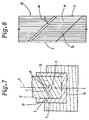
- a belt ply (p) is formed by wrapping a strip (e) of rubberised parallel cords (b) around the carcass.
- the strip (e) of rubberised parallel cords (b) is made by cutting a sheet of tyre fabric (d) at a bias angle ( ⁇ ).
- the ends (f) of the strip (e) are joined by overlapping one end on the other with a small overlap, and a lap joint running at the bias angle ( ⁇ ) is thus formed.
- the belt also has two side edges around the tyre circumference which have cut ends for the cords forming the belt.
- an object of the present invention to provide a pneumatic tyre which can solve the problems of stability, durability and drifting.
- a pneumatic tyre comprises a carcass extending between beads and a belt disposed radially outside the carcass and inside a tread and having opposite axial edges
- the belt comprises a ribbon of rubber in which a plurality of cords are embedded extending in the longitudinal direction thereof
- the ribbon is continuously wound around the carcass and folded back at the edges of the belt to extend zigzag between the edges of the belt so as to define ribbon segments comprising cord segments extending between the edges of the belt, the cord segments including first cord segments and second cord segments, the first cord segments being laid substantially parallel to each other, and the second cord segments being laid substantially parallel to each other and crosswise to the first cord segments characterised in that the folding back of the ribbon at each edge is from radially inwards to outwards, the zigzag pitch is substantially equal to an integral number of times the circumferential width of the ribbon, whereby the ribbon segments are arranged tightly together in the circumferential direction of the tyre with respect to the tyre
- a pneumatic tyre 1 has a tread 2, a pair of axially spaced bead portions 4, and a pair of sidewalls 3 extending between the tread edges and the bead portions 4.
- a bead core 4A is disposed in each bead portion 4 and a toroidal carcass 5 extends between the bead portions 4 and is turned up around the bead cores 4A.
- a jointless belt 6 is disposed radially outside the carcass 5 and inside the tread 2.
- the carcass 5 in this embodiment comprises one ply of organic fibre cords, e.g. nylon, aromatic polyamide or the like, arranged radially at an angle of 60 to 90 degrees with respect to the tyre equator C so as to provide a radial or a so called semiradial ply construction.
- organic fibre cords e.g. nylon, aromatic polyamide or the like
- the belt 6 comprises at least one continuous cord which is wound at least once around the carcass while running zigzag from one edge to the other edge of the belt, so that the or each belt cord has first parallel cord segments inclined at a bias angle ( ⁇ ) with respect to the tyre equator and second parallel cord segments inclined at the same bias angle ( ⁇ ) but in the opposite symmetrical direction with respect to the tyre equator.
- each cord segment is a substantially straight cord portion defined as extending from one edge to the other edge of the belt.
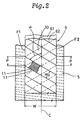
- Fig.2 shows a first example of the belt 6, in which several parallel cords 11 in the form of a strip are wound together several times around the carcass.
- the first parallel cord segments 61 are located radially inside the second parallel cord segments 62.
- Fig.3 shows a strip or ribbon 10 of rubber.
- a ribbon In order to make the belt, such a ribbon is used.
- one belt cord or several parallel belt cords 11 is/are embedded in coating rubber 12.
- the number of embedded cords 11 is in the range of 1 to 10. In the example shown in Fig.3, the number is 7, and the cross sectional shape of the ribbon 10 is a flat rectangle.
- the width Wo of the ribbon 10 is in the range of 5 to 15 mm.
- organic fibre cords e.g. nylon, polyester, aromatic polyamide or the like or steel cords can be used.
- aromatic polyamide fibre cords are used for their high modulus, which corresponds to that of steel cords, and their light weight.
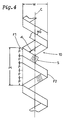
- Fig.4 shows a method of making the belt 6 shown in Fig.2, wherein one ribbon 10 is wound around the tyre a plurality of times (n) as follows:- In the fist winding, the ribbon extends at an angle ( ⁇ ) from a starting point S to the other (left side) belt edge F1;
- the ribbon is wound in the same way as the first winding.
- the belt By winding the ribbon (n)-times around the tyre, the belt becomes complete and closely packed. In other words, no spaces are left between the circumferentially adjacent ribbon segments (used in the same sense as the above-mentioned cord segments).
- the zigzag pitch Pt in the circumferential direction of the tyre is (n) times the circumferential width P of the ribbon.
- the terminal end thereof After the (n)-time winding of the ribbon, the terminal end thereof returns to the first starting point S and is joined to the starting end.
- the ribbon is always folded back from a radially outward direction to a radially inward direction at the left side edge F1 and from radially inward to radially outward at the right side edge F2.
- the ribbon is wound spirally and continuously around the central plane of the belt while being wound around the carcass generally.
- Such a spiral-folding type belt is formed separately from the carcass, and thereafter they are assembled.
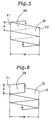
- Fig.5 shows a modification of the above-explained belt 6.
- the zigzag pitch Pt is equal to the circumferential width P of the ribbon, and accordingly the bias angle of the belt cords becomes larger, and the ribbon is wound once around the carcass.
- Fig.6 shows a modification of the belt 6a shown in Fig.5.
- this belt 6b the folding-back directions of the ribbon at the belt edges are altered such that the ribbon is folded back from radially inside to outside at both the edges F1 and F2, which makes it possible to form the belt 6b directly on the carcass. It is however, also possible to form this belt separately from the carcass.
- Such one-way folding can be applied to the first example belt 6.
- the circumferential length of one winding of the ribbon can be larger than that of the belt.
- the difference therebetween is set to be the circumferential width P of the ribbon.
- the starting points for the second to last windings are positioned behind and adjacent to the respective previous starting points.
- the above-mentioned bias angle ( ⁇ ) of the ribbon 10 or belt cords 11 may be in the range of 10 to 80 degrees with respect to the tyre equator.
- the edges of the adjacent ribbon segments are not overlapped. However, they may be slightly overlapped.
- a further layer can be formed successively thereon by continuously winding the ribbon therearound.
- the axial extent W of the zigzag is preferably changed to be narrower or wider than the other layer.
- a further layer can be formed successively by continuously winding the ribbon around the previously formed belt layer.
- a belt layer made of a strip of conventional tyre fabric can be combined with the above- mentioned zigzag cord belts 6, 6a and 6b.
- a fabric belt layer may be disposed between the radially outer segments 62 and the radially inner segments 61 of the zigzag cord belt formed by spiral folding, or a fabric belt layer may be disposed radially outside or inside the zigzag cord belt.
- the belt is provided with an endless structure with respect to the circumferential direction of the tyre, and there is no cord cut end at the edges, and further, the first cord segments cross the second cord segments.
- the endless structure and cross structure provide a rigid and uniform reinforcement for the tread portion, and straight running performance and steering stability are improved.
Landscapes
- Engineering & Computer Science (AREA)
- Mechanical Engineering (AREA)
- Tires In General (AREA)
- Tyre Moulding (AREA)
Applications Claiming Priority (3)
| Application Number | Priority Date | Filing Date | Title |
|---|---|---|---|
| JP2301659A JPH04173404A (ja) | 1990-11-06 | 1990-11-06 | 空気入りタイヤ |
| JP301659/90 | 1990-11-06 | ||
| EP91310163A EP0485136B1 (de) | 1990-11-06 | 1991-11-04 | Luftreifen |
Related Parent Applications (2)
| Application Number | Title | Priority Date | Filing Date |
|---|---|---|---|
| EP91310163.0 Division | 1991-11-04 | ||
| EP91310163A Division EP0485136B1 (de) | 1990-11-06 | 1991-11-04 | Luftreifen |
Publications (2)
| Publication Number | Publication Date |
|---|---|
| EP0611023A2 true EP0611023A2 (de) | 1994-08-17 |
| EP0611023A3 EP0611023A3 (de) | 1994-08-24 |
Family
ID=17899596
Family Applications (2)
| Application Number | Title | Priority Date | Filing Date |
|---|---|---|---|
| EP9494201413A Withdrawn EP0611023A3 (de) | 1990-11-06 | 1991-11-04 | Luftreifen |
| EP91310163A Expired - Lifetime EP0485136B1 (de) | 1990-11-06 | 1991-11-04 | Luftreifen |
Family Applications After (1)
| Application Number | Title | Priority Date | Filing Date |
|---|---|---|---|
| EP91310163A Expired - Lifetime EP0485136B1 (de) | 1990-11-06 | 1991-11-04 | Luftreifen |
Country Status (4)
| Country | Link |
|---|---|
| US (1) | US5535801A (de) |
| EP (2) | EP0611023A3 (de) |
| JP (1) | JPH04173404A (de) |
| DE (1) | DE69118316T2 (de) |
Families Citing this family (26)
| Publication number | Priority date | Publication date | Assignee | Title |
|---|---|---|---|---|
| JP3644728B2 (ja) * | 1995-07-26 | 2005-05-11 | 横浜ゴム株式会社 | 空気入りラジアルタイヤ |
| JP3614218B2 (ja) * | 1995-10-24 | 2005-01-26 | 横浜ゴム株式会社 | 空気入りタイヤ |
| JP3644744B2 (ja) * | 1996-02-15 | 2005-05-11 | 横浜ゴム株式会社 | 空気入りラジアルタイヤ |
| EP0875402A4 (de) * | 1996-07-25 | 2001-03-14 | Yokohama Rubber Co Ltd | Radialer luftreifen |
| FR2757799B1 (fr) * | 1996-12-27 | 1999-02-05 | Michelin & Cie | Armature de sommet pour pneumatique d'avion |
| JP3636562B2 (ja) * | 1997-02-10 | 2005-04-06 | 横浜ゴム株式会社 | 乗用車用空気入りラジアルタイヤ |
| JP3683065B2 (ja) * | 1997-02-17 | 2005-08-17 | 横浜ゴム株式会社 | 空気入りラジアルタイヤ |
| JP3837238B2 (ja) * | 1998-07-17 | 2006-10-25 | 横浜ゴム株式会社 | 空気入りラジアルタイヤ |
| JP3878754B2 (ja) * | 1998-10-05 | 2007-02-07 | 横浜ゴム株式会社 | 空気入りラジアルタイヤ |
| US6851463B1 (en) | 1999-04-08 | 2005-02-08 | Alliedsignal Inc. | Composite comprising organic fibers having a low twist multiplier and improved compressive modulus |
| US6352093B1 (en) * | 1999-12-28 | 2002-03-05 | The Goodyear Tire & Rubber Company | Continuous folded belt and splice therefor |
| JP4309339B2 (ja) * | 2002-05-29 | 2009-08-05 | ソシエテ ド テクノロジー ミシュラン | ストリップを回転表面に取り付けるための装置および方法 |
| US20040163748A1 (en) * | 2003-02-24 | 2004-08-26 | Kiyoshi Ueyoko | Tire having a composite belt structure |
| US7360571B2 (en) * | 2003-09-16 | 2008-04-22 | The Goodyear Tire & Rubber Company | Pneumatic tire with composite belt structure |
| US7216684B2 (en) * | 2003-12-29 | 2007-05-15 | The Goodyear Tire & Rubber Company | Pneumatic aviation tire |
| JP4880207B2 (ja) * | 2004-06-16 | 2012-02-22 | 東洋ゴム工業株式会社 | ゴム製筒体 |
| JP4963858B2 (ja) * | 2006-04-13 | 2012-06-27 | 株式会社ブリヂストン | 航空機用タイヤおよびそれの製造方法 |
| US9168789B2 (en) | 2008-12-19 | 2015-10-27 | The Goodyear Tire & Rubber Company | Truck tire |
| US20100154964A1 (en) * | 2008-12-19 | 2010-06-24 | Francois Pierre Charles Gerard Georges | Pneumatic tire |
| US20100154965A1 (en) * | 2008-12-19 | 2010-06-24 | Roland Willibrord Krier | Offset zigzag belt structure for a pneumatic tire |
| US20100154974A1 (en) * | 2008-12-19 | 2010-06-24 | Francois Pierre Charles Gerard Georges | Method of making a pneumatic tire |
| US8079392B2 (en) * | 2008-12-19 | 2011-12-20 | The Goodyear Tire & Rubber Company | Alternating straight/wavy reinforcement structure for pneumatic tire |
| FR2952326B1 (fr) * | 2009-11-09 | 2012-09-28 | Michelin Soc Tech | Pneumatique comportant au moins deux bi-couches |
| JP6501113B2 (ja) * | 2015-05-13 | 2019-04-17 | 株式会社ブリヂストン | 空気入りタイヤ |
| JP6861542B2 (ja) * | 2017-03-08 | 2021-04-21 | 株式会社ブリヂストン | 空気入りタイヤ |
| JP2020093661A (ja) * | 2018-12-12 | 2020-06-18 | 株式会社ブリヂストン | タイヤ |
Family Cites Families (14)
| Publication number | Priority date | Publication date | Assignee | Title |
|---|---|---|---|---|
| NL88195C (de) * | 1954-03-05 | |||
| US3563296A (en) * | 1968-11-18 | 1971-02-16 | Thomas A Wells | Folded endless reinforcement for pneumatic tires |
| US3770042A (en) * | 1970-09-03 | 1973-11-06 | Deering Milliken Res Corp | Endless reinforcement and method for producing same |
| US3830276A (en) * | 1973-08-20 | 1974-08-20 | Goodyear Tire & Rubber | Tire with folded breaker belt splicing |
| US4002789A (en) * | 1974-01-10 | 1977-01-11 | Deering Milliken Research Corporation | Endless reinforcement |
| US4002739A (en) * | 1975-02-18 | 1977-01-11 | Warner-Lambert Company | Soluble collagen |
| FR2361230A1 (fr) * | 1976-08-11 | 1978-03-10 | Uniroyal | Structure de ceinture de renforcement d'enveloppe de bandage pneumatique |
| JPS5576182A (en) * | 1978-11-30 | 1980-06-09 | Fuji Shoji | Steel cord and tire using steel cord |
| JPS5579706A (en) * | 1978-12-07 | 1980-06-16 | Fuji Shoji Kk | Reinforcement ring for tire breaker |
| JPS58160805A (ja) * | 1982-03-18 | 1983-09-24 | Nippon Steel Corp | 大口径鋼管の寸法、形状測定方法 |
| GB8413093D0 (en) * | 1984-05-22 | 1984-06-27 | Apsley Metals Ltd | Tyres |
| US4838966A (en) * | 1986-11-12 | 1989-06-13 | The Armstrong Rubber Co. | Woven endless tire reinforcing belt and method for producing same |
| JP3126516B2 (ja) * | 1991-10-29 | 2001-01-22 | 株式会社ブリヂストン | 航空機用ラジアルタイヤ |
| US5465773A (en) * | 1993-04-30 | 1995-11-14 | Bridgestone Corporation | Pneumatic radial tires with zigzag belt and rubberized cord ply belt reinforcing layer |
-
1990
- 1990-11-06 JP JP2301659A patent/JPH04173404A/ja active Pending
-
1991
- 1991-11-04 EP EP9494201413A patent/EP0611023A3/de not_active Withdrawn
- 1991-11-04 EP EP91310163A patent/EP0485136B1/de not_active Expired - Lifetime
- 1991-11-04 DE DE69118316T patent/DE69118316T2/de not_active Expired - Fee Related
-
1994
- 1994-07-08 US US08/272,310 patent/US5535801A/en not_active Expired - Fee Related
Also Published As
| Publication number | Publication date |
|---|---|
| EP0485136B1 (de) | 1996-03-27 |
| DE69118316T2 (de) | 1996-08-08 |
| EP0611023A3 (de) | 1994-08-24 |
| EP0485136A1 (de) | 1992-05-13 |
| DE69118316D1 (de) | 1996-05-02 |
| US5535801A (en) | 1996-07-16 |
| JPH04173404A (ja) | 1992-06-22 |
Similar Documents
| Publication | Publication Date | Title |
|---|---|---|
| EP0485136B1 (de) | Luftreifen | |
| EP0501782B1 (de) | Luftreifen | |
| EP0453294B1 (de) | Gürtelluftreifen für Motorräder und Verfahren zur Herstellung | |
| EP0455454B1 (de) | Radialluftreifen | |
| EP0117137B1 (de) | Verbindung von Reifenlagen und Verfahren zu ihrer Herstellung | |
| EP0455453A2 (de) | Radialer Luftreifen für Motorräder | |
| US5441093A (en) | Motorcycle radial tire with folded breaker ply and spirally wound band ply | |
| JPH01278803A (ja) | 空気タイヤおよびその製造方法 | |
| EP0916522B1 (de) | Verbesserte Luftreifenkonstruktion und Verfahren zur Herstellung | |
| GB2253818A (en) | Tyre belt making method and tyre | |
| US5419384A (en) | Pneumatic tire including a carcass ply composed of a plurality of ply strips | |
| JPS62203803A (ja) | 空気入りタイヤの製造方法 | |
| US5178703A (en) | Breaker with wound band | |
| EP0425318B1 (de) | Radialer Luftreifen | |
| EP0456438A2 (de) | Radialer Luftreifen für Motorräder | |
| US5386866A (en) | Radial tire with band formed from plural ribbons | |
| JP2001071710A (ja) | 車両用タイヤ | |
| JP2660521B2 (ja) | 空気入りタイヤ | |
| JP2878346B2 (ja) | 空気入りラジアルタイヤ | |
| JPH1134609A (ja) | 空気入りラジアルタイヤ | |
| JP3224857B2 (ja) | 自動二輪車用ラジアルタイヤ | |
| JP3061322B2 (ja) | 航空機用ラジアルタイヤ | |
| JP2996341B2 (ja) | 空気入りラジアルタイヤ | |
| JPH08132822A (ja) | 空気入りタイヤ |
Legal Events
| Date | Code | Title | Description |
|---|---|---|---|
| PUAI | Public reference made under article 153(3) epc to a published international application that has entered the european phase |
Free format text: ORIGINAL CODE: 0009012 |
|
| PUAL | Search report despatched |
Free format text: ORIGINAL CODE: 0009013 |
|
| 17P | Request for examination filed |
Effective date: 19940518 |
|
| AC | Divisional application: reference to earlier application |
Ref document number: 485136 Country of ref document: EP |
|
| AK | Designated contracting states |
Kind code of ref document: A2 Designated state(s): DE FR GB |
|
| AK | Designated contracting states |
Kind code of ref document: A3 Designated state(s): DE FR GB |
|
| RIN1 | Information on inventor provided before grant (corrected) |
Inventor name: SAKAMOTO, MASAYUKI Inventor name: ISEKI, TSUTOMU, 1-5 AZA-DOUJYOUMEN |
|
| 17Q | First examination report despatched |
Effective date: 19951212 |
|
| STAA | Information on the status of an ep patent application or granted ep patent |
Free format text: STATUS: THE APPLICATION HAS BEEN WITHDRAWN |
|
| 18W | Application withdrawn |
Withdrawal date: 19960320 |