EP0611093A2 - Orthèse du genou - Google Patents
Orthèse du genou Download PDFInfo
- Publication number
- EP0611093A2 EP0611093A2 EP94300781A EP94300781A EP0611093A2 EP 0611093 A2 EP0611093 A2 EP 0611093A2 EP 94300781 A EP94300781 A EP 94300781A EP 94300781 A EP94300781 A EP 94300781A EP 0611093 A2 EP0611093 A2 EP 0611093A2
- Authority
- EP
- European Patent Office
- Prior art keywords
- brace
- gear means
- joint
- members
- brace member
- Prior art date
- Legal status (The legal status is an assumption and is not a legal conclusion. Google has not performed a legal analysis and makes no representation as to the accuracy of the status listed.)
- Withdrawn
Links
Images

Classifications
-
- A—HUMAN NECESSITIES
- A61—MEDICAL OR VETERINARY SCIENCE; HYGIENE
- A61F—FILTERS IMPLANTABLE INTO BLOOD VESSELS; PROSTHESES; DEVICES PROVIDING PATENCY TO, OR PREVENTING COLLAPSING OF, TUBULAR STRUCTURES OF THE BODY, e.g. STENTS; ORTHOPAEDIC, NURSING OR CONTRACEPTIVE DEVICES; FOMENTATION; TREATMENT OR PROTECTION OF EYES OR EARS; BANDAGES, DRESSINGS OR ABSORBENT PADS; FIRST-AID KITS
- A61F5/00—Orthopaedic methods or devices for non-surgical treatment of bones or joints; Nursing devices ; Anti-rape devices
- A61F5/01—Orthopaedic devices, e.g. long-term immobilising or pressure directing devices for treating broken or deformed bones such as splints, casts or braces
- A61F5/0102—Orthopaedic devices, e.g. long-term immobilising or pressure directing devices for treating broken or deformed bones such as splints, casts or braces specially adapted for correcting deformities of the limbs or for supporting them; Ortheses, e.g. with articulations
- A61F5/0123—Orthopaedic devices, e.g. long-term immobilising or pressure directing devices for treating broken or deformed bones such as splints, casts or braces specially adapted for correcting deformities of the limbs or for supporting them; Ortheses, e.g. with articulations for the knees
-
- A—HUMAN NECESSITIES
- A61—MEDICAL OR VETERINARY SCIENCE; HYGIENE
- A61F—FILTERS IMPLANTABLE INTO BLOOD VESSELS; PROSTHESES; DEVICES PROVIDING PATENCY TO, OR PREVENTING COLLAPSING OF, TUBULAR STRUCTURES OF THE BODY, e.g. STENTS; ORTHOPAEDIC, NURSING OR CONTRACEPTIVE DEVICES; FOMENTATION; TREATMENT OR PROTECTION OF EYES OR EARS; BANDAGES, DRESSINGS OR ABSORBENT PADS; FIRST-AID KITS
- A61F5/00—Orthopaedic methods or devices for non-surgical treatment of bones or joints; Nursing devices ; Anti-rape devices
- A61F5/01—Orthopaedic devices, e.g. long-term immobilising or pressure directing devices for treating broken or deformed bones such as splints, casts or braces
- A61F5/0102—Orthopaedic devices, e.g. long-term immobilising or pressure directing devices for treating broken or deformed bones such as splints, casts or braces specially adapted for correcting deformities of the limbs or for supporting them; Ortheses, e.g. with articulations
- A61F2005/0132—Additional features of the articulation
- A61F2005/0137—Additional features of the articulation with two parallel pivots
- A61F2005/0139—Additional features of the articulation with two parallel pivots geared
Definitions
- the present invention relates to an improved knee brace having good stability.
- the brace Whilst the knee brace is primarily intended for orthopaedic use, the brace may be used as a prophylactic device for use in sport, for example, in skiing and wherein two joint means are provided one either side of the knee joint.
- an improved knee brace comprising upper and lower leg-engaging/embracing parts (thigh and calf pieces) connectable around upper and lower parts of the leg above and below the knee joint with the upper and lower leg embracing parts having upper and lower brace members respectively interconnected by at least one joint means, characterised by the feature that said joint means each comprises at least one link member pivotally connected to each of said brace members for holding said brace members together, wherein first and second gear means are provided on the upper and lower brace members and lie on arcs with the arc of the upper brace member having a smaller radius than the arc of the lower member and the gear means are such that the upper brace member rotates at a faster angular velocity than the lower so as to closely resemble the movement of a knee joint.
- an improved knee brace comprising upper and lower leg-engaging/embracing parts (thigh and calf pieces) connectable around upper and lower parts of the leg above and below the knee joint with the upper and lower leg embracing parts having upper and lower brace members respectively interconnected by at least one joint means, characterised by the feature that said joint means each comprises at least one link member pivotally connected to each of said brace members for holding such together, wherein the end region of the normally upper brace member has a slot or passage therein defined between two arm portions of said member and in which slot a first gear means is provided comprising a series of cross members, preferably in the form of short cylinders or pins, arranged on an arc on a first radius which does not extend beyond the end of said upper member and wherein the end region of the lower brace member is provided with a second gear means formed as a series of recesses cooperably receiving said cross members and arranged as an arc on a second radius which is longer than the radius of said first arc and the gear means such
- an improved knee brace comprising upper and lower leg-engaging/embracing parts (thigh and calf pieces) connectable around upper and lower parts of the leg above and below the knee joint with the upper and lower leg embracing parts having upper and lower brace members respectively interconnected by at least one joint means, characterised by the feature that said joint means each comprises at least one link member pivotally connected at pivot points to rotate about a pivotal axis on each of said brace members with said at least one link member being provided for holding said brace members together, and wherein the end region of a first said brace member has a slot defined between two end arm portions and within the slot space or forming a defining portion thereof, a first gear means is provided and such is engaged by second gear means on the end of the second brace member which second gear means is displaceable in said slot to engage said first gear means; and wherein said first and second gear means lie on arcs each concentric with the pivot point of the brace member on which it is provided and with the arc of the upper brace
- the gear means of the second or lower brace member is an arcuate or otherwised curved or shaped portion and provided having a plurality of spaced apart curved or otherwise shaped recesses each for temporarily receiving a crank, pin, cross piece integrally formed gear means or other drive means arcuately or otherwise on the lower, first brace member.
- the link and gear means forms a planetary hinge or gear preferably with slot and pin action. It has been found particularly advantageous for the pins, other cross members or other drive means of the first, upper brace member to be spaced closer to the pivotal axis of the link member on said first upper, member so that when the brace members are moved concurrently the upper, first brace member rotates at a faster angular velocity than the lower, second brace member - thereby more closely proximating the movement of an actual knee joint.
- the gear means on the upper brace member is disposed on an arc of smaller radius than the gear means of the lower brace member and the gear means such that the upper joint part is displaced more than the lower.
- the selection of the pitch and/or gear ratio to achieve the desired movement is of importance. It is considered that any gear means therefor which achieves such effect would also fall within the scope of the present invention. It is even envisaged that the gear means may be a Geneva mechanism which will produce intermittent motion.
- the upper, first brace member which is to have the pins or other drive means of the gear means is formed so as to have the bifurcated end wherein in the slot thus defined said pins extend thereacross and are secured so as to act to hold the arms together to prevent or minimise lateral flexing.
- the slotted/recessed portion of the gear means being provided on the end of the lower, second brace member and being displaceable in the slot provided by the bifurcated ends of the first member and preferably in close relationship to provide a stable interrelationship.
- the arrangement provides good lateral stability on all positions of the joint so as to facilitate the joint to withstand lateral impacts.
- the upper brace member with the bifurcated end is integrally formed, for example, by moulding or otherwise forming from plastics or like material or by machining from a solid part such as a metal part.
- brace members other than such forming the gear means portion
- the adjacent ends of the actual brace members will not be in rolling abutment although may be in abutment in one end position as a stop to prevent hyperextension.
- two link members will preferably be provided one on opposite sides of the ends of the brace or joint members and sandwiching the gear means therebetween.
- the gear mechanism is constructed such that when the brace parts are moved concurrently the two arms move at different velocities or angular displacements.
- brace members may instead be joint parts which themselves are connected to or connectable to said brace members.
- knee brace of the present invention may have a single joint means for location on one side of the knee joint, it is preferable that the knee brace will incorporate two such joints locatable one either side of the knee joint for increased stability and support.
- a range of motion facility will be provided to limit the movement to prevent hyperextension and preferably such will be adjustable.
- Suitable stop surfaces may be provided in the side plates and/or on the adjacent surfaces of the joint members.
- the present invention has been described in relation to a knee brace but is also intended to be of such scope as to cover the joint per se .
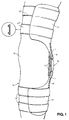
- a knee brace 11 is illustrated in Fig. 1 comprising a thigh cup 12 with associated securing straps 12' and a calf piece 13 with associated securing straps 13'.
- a user's left leg 14 is partially illustrated in broken line with the knee cap region being at 15.
- a joint 16 according to the invention is generally indicated with brace members 1 thereof being fixedly secured to cup 12 and piece 13.
- Two cushion pads 17 are provided on the inner side of joint 16 between such and knee 15.
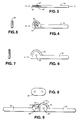
- the brace members and gear means illustrated in Figs. 2 - 9 is of a preferred embodiment and comprises an upper part brace part or member 18 formed as a single piece, e.g. by machining or moulding, and having a plurality of pins or like drive means 19 with the gear forming parts being arcuately arranged wholly within in the slot 20 defined by the bifurcation and acting to hold the arms 18' of the bifurcation together.
- the pins 19 will comprise screwed in metal parts which provide additional stability for the end of the brace member 18 which is preferably formed of a strong material such as carbon fibre or nylon.
- An aperture 21 is provided concentrically with the arc of the pin arrangement and two link members 22 (only one shown) are pivotally connected therewith, via pivot pins 23 in known manner on opposite sides of brace member 18 and also pivotally connected via pivot 25 extends through a lower brace member 24 and on opposite sides thereof.
- the lower brace member 24 is formed having an arcuate portion 26 fixed/stationary relative thereto by being integrally formed and having a plurality of curved recesses or slots 27 on the outer edge thereof which are shaped and dimensioned and spaced so as to engage with the pins 19 of the upper brace member 18 and thereby form the gear means.
- the gear means is such that two pins will engage in the recesses at any one time or be approximating such engagement such that continuous movement is achieved.
- pins may be provided every 15° (although with a Geneva mechanism the spacing may be at every 28°).
- the arcuate portion 26 and adjacent portions fit closely between the arms 18' with minimal spacing such that additional stability for the arrangement is advantageously obtained.
- the spacing between the pins 19 and the axis of rotation 23' of the upper base member 18 on which they are located is less than the spacing from axis of rotation 25' of the adjacent brace member so as to thereby achieve a movement wherein the upper brace member 18 rotates at faster angularly velocity than the lower brace member.
- the two brace members 18,24 move at different velocities and thereby more closely approximate the movement of a knee joint.
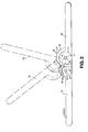
- Fig. 10 the ends of two link members 28 are illustrated in enlarged scale and spaced apart.
- a spiral cam 29 is rotatably and adjustably mounted at 29' and sandwiched between the two members 28 to abut the edge of a brace member.
- a second indentical or similar spiral cam (not shown) is similarly rotatably adjustably mounted at 30 in the diagonally opposite corner so that the spiral cams will limit motion in each direction of movement of the joint means to restrict flexion but are adjustable in position of fixing to enable the range of movement to be adjacent.
- the spiral cams in the diagonal corners between the two side plates or link members 28 when turned, will abut against edges of the brace members sooner as the radius increases - so providing limiting of motion for the joint means i.e. restricting flexion. Also, their position will strengthen the joint by holding the link members together in diagonal corners.
- an improved knee brace comprising upper and lower leg-engaging/embracing parts (thigh and calf pieces) connectable around upper and lower parts of the leg above and below the knee joint with the upper and lower leg embracing parts having upper and lower brace members respectively interconnected by at least one joint means, characterised by the feature that said joint means each comprises at least one link member pivotally connected at pivot points to rotate about a pivotal axis on each of said brace members with said at least one link member being provided for holding said brace members together and maintaining gear means thereof interengaged; and wherein the end region of a first said brace member has a slot defined between two end arm portions and within said slot space a portion of the end of the second brace member is displaceable in close proximity to said arms so as to act to restrict lateral displacement of the joint means.
- the gear means is provided within the slot and on the end of the second brace member.
- the gear means of the second or lower brace member of this different aspect is an arcuate or otherwised curved or shaped portion and provided having a plurality of spaced apart curved or otherwise shaped recesses each for temporarily receiving a crank, pin, cross piece, integrally formed gear means or other drive means arcuately or otherwise on the lower, first brace member.
- the link and gear means of this aspect also form a planetary hinge or gear preferably with slot and pin action and preferably as hereinbefore described.
Landscapes
- Health & Medical Sciences (AREA)
- Nursing (AREA)
- Orthopedic Medicine & Surgery (AREA)
- Engineering & Computer Science (AREA)
- Biomedical Technology (AREA)
- Heart & Thoracic Surgery (AREA)
- Vascular Medicine (AREA)
- Life Sciences & Earth Sciences (AREA)
- Animal Behavior & Ethology (AREA)
- General Health & Medical Sciences (AREA)
- Public Health (AREA)
- Veterinary Medicine (AREA)
- Orthopedics, Nursing, And Contraception (AREA)
- Prostheses (AREA)
Applications Claiming Priority (6)
| Application Number | Priority Date | Filing Date | Title |
|---|---|---|---|
| GB939302227A GB9302227D0 (en) | 1993-02-05 | 1993-02-05 | Improved knee brace |
| GB9302227 | 1993-02-05 | ||
| GB939303018A GB9303018D0 (en) | 1993-02-05 | 1993-02-15 | Improved knee brace |
| GB9303018 | 1993-02-15 | ||
| GB9305104 | 1993-03-12 | ||
| GB9305104A GB2274782B (en) | 1993-02-05 | 1993-03-12 | Improved knee brace |
Publications (2)
| Publication Number | Publication Date |
|---|---|
| EP0611093A2 true EP0611093A2 (fr) | 1994-08-17 |
| EP0611093A3 EP0611093A3 (fr) | 1994-08-31 |
Family
ID=27266567
Family Applications (1)
| Application Number | Title | Priority Date | Filing Date |
|---|---|---|---|
| EP19940300781 Withdrawn EP0611093A3 (fr) | 1993-02-05 | 1994-02-02 | Orthèse du genou |
Country Status (2)
| Country | Link |
|---|---|
| US (1) | US5419754A (fr) |
| EP (1) | EP0611093A3 (fr) |
Cited By (2)
| Publication number | Priority date | Publication date | Assignee | Title |
|---|---|---|---|---|
| WO1999026564A1 (fr) * | 1997-11-21 | 1999-06-03 | Hjs Gelenk System Gmbh | Exoprothese destinee a l'articulation du genou de l'homme |
| US7235058B2 (en) | 2002-09-11 | 2007-06-26 | Djo, Llc | Lockable hinge |
Families Citing this family (20)
| Publication number | Priority date | Publication date | Assignee | Title |
|---|---|---|---|---|
| US5827208A (en) * | 1995-11-28 | 1998-10-27 | Breg, Inc, | Hinge for an orthopedic brace having a selectively positionable stop to limit rotation |
| US5685811A (en) * | 1995-12-19 | 1997-11-11 | Mcshane; Jerry M. | Universal muscular conditioning device |
| US5776086A (en) * | 1996-01-11 | 1998-07-07 | Pansiera; Timothy T. | Hinge system for an orthopedic brace |
| CA2386905C (fr) * | 1999-12-21 | 2008-10-07 | Dj Orthopedics, Llc | Ensemble charniere pour une orthese orthopedique du genou et orthese du genou comprenant cet ensemble charniere |
| US6527733B1 (en) * | 2000-02-22 | 2003-03-04 | Dj Orthopedics, Llc | Hinge assembly for an orthopedic knee brace and knee brace incorporating the hinge assembly |
| JP3740638B2 (ja) * | 2001-11-28 | 2006-02-01 | 準平 山崎 | 膝ブレ−ス |
| US7488300B2 (en) | 2002-02-15 | 2009-02-10 | Thusane | Bicentric hinge for use in a brace |
| US6969363B2 (en) * | 2002-02-15 | 2005-11-29 | Thuasne | Bicentric hinge for use in a brace |
| US7192407B2 (en) * | 2003-01-30 | 2007-03-20 | Djo, Llc | Motion controlling hinge for orthopedic brace |
| US7150721B2 (en) * | 2003-06-30 | 2006-12-19 | Thuasne | Knee brace with dynamic counterforce |
| US20050273025A1 (en) * | 2004-05-19 | 2005-12-08 | Houser Guy M | Braces having an assembly for exerting a manually adjustable force on a limb of a user |
| US7811242B2 (en) * | 2004-06-24 | 2010-10-12 | Djo, Llc | Motion controlling hinge for orthopedic brace |
| US7544174B2 (en) | 2006-09-29 | 2009-06-09 | Djo, Llc | Quiet flexion/extension stop for orthopedic brace and orthopedic brace incorporating a quiet flexion/extension stop |
| ITRM20130100A1 (it) * | 2013-02-21 | 2014-08-22 | Tecnoway S A S | Tutore per articolazione. |
| US11839564B1 (en) | 2019-08-08 | 2023-12-12 | Preferred Prescription, INC | Knee orthosis, adjustable |
| US12121463B1 (en) | 2020-02-13 | 2024-10-22 | Preferred Prescription, Inc. | Knee/elbow brace |
| USD986423S1 (en) * | 2020-03-26 | 2023-05-16 | Ossur Iceland Ehf | Orthopedic Frame |
| USD986422S1 (en) * | 2020-03-26 | 2023-05-16 | Ossur Iceland Ehf | Orthopedic frame |
| US11918500B1 (en) | 2020-03-31 | 2024-03-05 | Preferred Prescription, Inc. | Hinged knee brace with double upper strap arrangement |
| US12447032B2 (en) | 2022-02-02 | 2025-10-21 | Djo, Llc | Single-upright osteoarthritis braces and related methods |
Family Cites Families (15)
| Publication number | Priority date | Publication date | Assignee | Title |
|---|---|---|---|---|
| US2883982A (en) * | 1956-09-06 | 1959-04-28 | Fred E Rainey | Leg brace |
| US4088130A (en) * | 1977-05-16 | 1978-05-09 | Surgical Appliance Industries, Inc. | Hinge for knee brace |
| US4372298A (en) * | 1981-07-20 | 1983-02-08 | U.S. Manufacturing Co. | Knee brace |
| US4493316A (en) * | 1983-03-10 | 1985-01-15 | Donjoy, Inc. | Articulating knee stabilizer |
| US4524764A (en) * | 1983-09-06 | 1985-06-25 | Miller Harold E | Knee brace |
| US4520802A (en) * | 1983-09-30 | 1985-06-04 | Mercer James D | Bi-axial orthotic device |
| US4633867A (en) * | 1984-06-27 | 1987-01-06 | James H. Kausek | Knee brace for control of ligament instability |
| US4655201A (en) * | 1984-07-13 | 1987-04-07 | Northwestern University | Knee orthosis and joint construction therefor |
| US4643176A (en) * | 1984-10-03 | 1987-02-17 | Don Joy, Inc. | Athletic knee protector with bowed leaf spring structure |
| US4697583A (en) * | 1985-01-29 | 1987-10-06 | Don Joy Orthopedic, Inc. | Four-point anterior cruciate ligament brace |
| CH671876A5 (en) * | 1986-09-09 | 1989-10-13 | Peter Dr Med Soyka | Knee joint orthosis or brace - has toothed segment which engages toothed back to simulate natural movement of knee joint |
| US4844057A (en) * | 1987-11-16 | 1989-07-04 | David Hoy | Knee orthotic hinge joint |
| CH679910A5 (fr) * | 1989-05-30 | 1992-05-15 | Broeck Marc Vanden | |
| US5038763A (en) * | 1989-09-15 | 1991-08-13 | Wiggins Christopher N | Knee brace |
| US5060640A (en) * | 1990-03-14 | 1991-10-29 | Becker Orthopedic Appliance Company | Knee brace |
-
1994
- 1994-02-02 EP EP19940300781 patent/EP0611093A3/fr not_active Withdrawn
- 1994-02-04 US US08/191,914 patent/US5419754A/en not_active Expired - Lifetime
Cited By (3)
| Publication number | Priority date | Publication date | Assignee | Title |
|---|---|---|---|---|
| WO1999026564A1 (fr) * | 1997-11-21 | 1999-06-03 | Hjs Gelenk System Gmbh | Exoprothese destinee a l'articulation du genou de l'homme |
| US7235058B2 (en) | 2002-09-11 | 2007-06-26 | Djo, Llc | Lockable hinge |
| US7722555B2 (en) | 2002-09-11 | 2010-05-25 | Djo, Llc | Lockable hinge |
Also Published As
| Publication number | Publication date |
|---|---|
| US5419754A (en) | 1995-05-30 |
| EP0611093A3 (fr) | 1994-08-31 |
Similar Documents
| Publication | Publication Date | Title |
|---|---|---|
| US5419754A (en) | Knee brace | |
| EP1578316B1 (fr) | Système d'articulation pour régler la flexion et l'extension de l'articulation du genou. | |
| US4554913A (en) | Adjustable joint for a knee brace | |
| US5009223A (en) | Variable axis knee brace | |
| CA2171022C (fr) | Rotule sans frottement servant de support orthopedique du genou | |
| US4463751A (en) | Stabilizing knee hinge | |
| US6203511B1 (en) | Orthotic joint and method | |
| US9345605B2 (en) | Hinge for an orthopedic device | |
| EP1703873B1 (fr) | Charnieres d'attelle de genou ayant un double axe de rotation | |
| US5086760A (en) | Articulated orthotic brace for an anatomical joint | |
| US5230696A (en) | Polycentric variable axis hinge for an orthopedic knee brace | |
| US4890607A (en) | Multiaxis controlled motion knee orthosis | |
| US4603690A (en) | Sliding pivot knee joint | |
| US6302858B1 (en) | Compound adjustable ankle foot orthosis brace | |
| EP3367981B1 (fr) | Ensemble de charnière pour dispositif orthopédique | |
| EP0528017A1 (fr) | Attelle pour genou a mouvement commande multiaxe avec articulation a quatre barres, et son procede de production | |
| US20210353438A1 (en) | Finger prosthesis with adjustable biological activation | |
| US7087031B2 (en) | Perfected jointed rod for a hip support | |
| US6746414B1 (en) | Joint for a knee brace incorporating a locking mechanism | |
| US5741221A (en) | Knee-joint orthesis having different medical and lateral hinge mechanisms | |
| JP6536960B2 (ja) | 膝関節アシスト装置の設計方法および膝関節アシスト装置 | |
| GB2274782A (en) | Knee brace | |
| KR20030015030A (ko) | 골절 환자의 회복운동장치 | |
| JP3752604B2 (ja) | 膝または肘関節装具用支柱 | |
| US20120035517A1 (en) | Orthotic fitting having a knee guide joint |
Legal Events
| Date | Code | Title | Description |
|---|---|---|---|
| PUAI | Public reference made under article 153(3) epc to a published international application that has entered the european phase |
Free format text: ORIGINAL CODE: 0009012 |
|
| PUAL | Search report despatched |
Free format text: ORIGINAL CODE: 0009013 |
|
| AK | Designated contracting states |
Kind code of ref document: A2 Designated state(s): AT BE CH DE DK ES FR GB GR IE IT LI LU MC NL PT SE |
|
| AK | Designated contracting states |
Kind code of ref document: A3 Designated state(s): AT BE CH DE DK ES FR GB GR IE IT LI LU MC NL PT SE |
|
| RBV | Designated contracting states (corrected) |
Designated state(s): CH DE ES FR GB IE LI NL PT SE |
|
| 17P | Request for examination filed |
Effective date: 19950224 |
|
| STAA | Information on the status of an ep patent application or granted ep patent |
Free format text: STATUS: THE APPLICATION IS DEEMED TO BE WITHDRAWN |
|
| 18D | Application deemed to be withdrawn |
Effective date: 19960830 |