EP0611097A1 - Source optique compacte comprenant un laser - Google Patents
Source optique compacte comprenant un laser Download PDFInfo
- Publication number
- EP0611097A1 EP0611097A1 EP94300786A EP94300786A EP0611097A1 EP 0611097 A1 EP0611097 A1 EP 0611097A1 EP 94300786 A EP94300786 A EP 94300786A EP 94300786 A EP94300786 A EP 94300786A EP 0611097 A1 EP0611097 A1 EP 0611097A1
- Authority
- EP
- European Patent Office
- Prior art keywords
- laser
- optical
- dbr
- facet
- optical fiber
- Prior art date
- Legal status (The legal status is an assumption and is not a legal conclusion. Google has not performed a legal analysis and makes no representation as to the accuracy of the status listed.)
- Withdrawn
Links
- 230000003287 optical effect Effects 0.000 title claims abstract description 53
- 239000013307 optical fiber Substances 0.000 claims abstract description 18
- 239000004065 semiconductor Substances 0.000 claims abstract description 12
- 230000005670 electromagnetic radiation Effects 0.000 claims description 8
- 238000010009 beating Methods 0.000 claims description 5
- 239000000835 fiber Substances 0.000 description 13
- 238000001228 spectrum Methods 0.000 description 6
- 238000004891 communication Methods 0.000 description 5
- VYPSYNLAJGMNEJ-UHFFFAOYSA-N Silicium dioxide Chemical compound O=[Si]=O VYPSYNLAJGMNEJ-UHFFFAOYSA-N 0.000 description 4
- 238000013461 design Methods 0.000 description 3
- 238000010586 diagram Methods 0.000 description 3
- 238000002310 reflectometry Methods 0.000 description 3
- 230000000087 stabilizing effect Effects 0.000 description 3
- 230000004075 alteration Effects 0.000 description 2
- 230000005540 biological transmission Effects 0.000 description 2
- 239000011248 coating agent Substances 0.000 description 2
- 238000000576 coating method Methods 0.000 description 2
- 230000000694 effects Effects 0.000 description 2
- 230000001902 propagating effect Effects 0.000 description 2
- 230000005855 radiation Effects 0.000 description 2
- 239000000377 silicon dioxide Substances 0.000 description 2
- 206010073306 Exposure to radiation Diseases 0.000 description 1
- 230000035559 beat frequency Effects 0.000 description 1
- BJQHLKABXJIVAM-UHFFFAOYSA-N bis(2-ethylhexyl) phthalate Chemical compound CCCCC(CC)COC(=O)C1=CC=CC=C1C(=O)OCC(CC)CCCC BJQHLKABXJIVAM-UHFFFAOYSA-N 0.000 description 1
- 238000002474 experimental method Methods 0.000 description 1
- 230000004927 fusion Effects 0.000 description 1
- 239000011521 glass Substances 0.000 description 1
- 238000000034 method Methods 0.000 description 1
- 238000012544 monitoring process Methods 0.000 description 1
- 238000011084 recovery Methods 0.000 description 1
- 230000008054 signal transmission Effects 0.000 description 1
- 230000003595 spectral effect Effects 0.000 description 1
Images
Classifications
-
- H—ELECTRICITY
- H04—ELECTRIC COMMUNICATION TECHNIQUE
- H04B—TRANSMISSION
- H04B10/00—Transmission systems employing electromagnetic waves other than radio-waves, e.g. infrared, visible or ultraviolet light, or employing corpuscular radiation, e.g. quantum communication
- H04B10/50—Transmitters
- H04B10/508—Pulse generation, e.g. generation of solitons
-
- H—ELECTRICITY
- H01—ELECTRIC ELEMENTS
- H01S—DEVICES USING THE PROCESS OF LIGHT AMPLIFICATION BY STIMULATED EMISSION OF RADIATION [LASER] TO AMPLIFY OR GENERATE LIGHT; DEVICES USING STIMULATED EMISSION OF ELECTROMAGNETIC RADIATION IN WAVE RANGES OTHER THAN OPTICAL
- H01S5/00—Semiconductor lasers
- H01S5/06—Arrangements for controlling the laser output parameters, e.g. by operating on the active medium
- H01S5/065—Mode locking; Mode suppression; Mode selection ; Self pulsating
-
- H—ELECTRICITY
- H01—ELECTRIC ELEMENTS
- H01S—DEVICES USING THE PROCESS OF LIGHT AMPLIFICATION BY STIMULATED EMISSION OF RADIATION [LASER] TO AMPLIFY OR GENERATE LIGHT; DEVICES USING STIMULATED EMISSION OF ELECTROMAGNETIC RADIATION IN WAVE RANGES OTHER THAN OPTICAL
- H01S5/00—Semiconductor lasers
- H01S5/10—Construction or shape of the optical resonator, e.g. extended or external cavity, coupled cavities, bent-guide, varying width, thickness or composition of the active region
- H01S5/14—External cavity lasers
- H01S5/146—External cavity lasers using a fiber as external cavity
-
- H—ELECTRICITY
- H04—ELECTRIC COMMUNICATION TECHNIQUE
- H04B—TRANSMISSION
- H04B10/00—Transmission systems employing electromagnetic waves other than radio-waves, e.g. infrared, visible or ultraviolet light, or employing corpuscular radiation, e.g. quantum communication
- H04B10/50—Transmitters
- H04B10/501—Structural aspects
- H04B10/503—Laser transmitters
- H04B10/504—Laser transmitters using direct modulation
-
- H—ELECTRICITY
- H01—ELECTRIC ELEMENTS
- H01S—DEVICES USING THE PROCESS OF LIGHT AMPLIFICATION BY STIMULATED EMISSION OF RADIATION [LASER] TO AMPLIFY OR GENERATE LIGHT; DEVICES USING STIMULATED EMISSION OF ELECTROMAGNETIC RADIATION IN WAVE RANGES OTHER THAN OPTICAL
- H01S5/00—Semiconductor lasers
- H01S5/06—Arrangements for controlling the laser output parameters, e.g. by operating on the active medium
- H01S5/065—Mode locking; Mode suppression; Mode selection ; Self pulsating
- H01S5/0657—Mode locking, i.e. generation of pulses at a frequency corresponding to a roundtrip in the cavity
-
- H—ELECTRICITY
- H01—ELECTRIC ELEMENTS
- H01S—DEVICES USING THE PROCESS OF LIGHT AMPLIFICATION BY STIMULATED EMISSION OF RADIATION [LASER] TO AMPLIFY OR GENERATE LIGHT; DEVICES USING STIMULATED EMISSION OF ELECTROMAGNETIC RADIATION IN WAVE RANGES OTHER THAN OPTICAL
- H01S5/00—Semiconductor lasers
- H01S5/10—Construction or shape of the optical resonator, e.g. extended or external cavity, coupled cavities, bent-guide, varying width, thickness or composition of the active region
- H01S5/12—Construction or shape of the optical resonator, e.g. extended or external cavity, coupled cavities, bent-guide, varying width, thickness or composition of the active region the resonator having a periodic structure, e.g. in distributed feedback [DFB] lasers
- H01S5/1206—Construction or shape of the optical resonator, e.g. extended or external cavity, coupled cavities, bent-guide, varying width, thickness or composition of the active region the resonator having a periodic structure, e.g. in distributed feedback [DFB] lasers having a non constant or multiplicity of periods
- H01S5/1212—Chirped grating
-
- H—ELECTRICITY
- H01—ELECTRIC ELEMENTS
- H01S—DEVICES USING THE PROCESS OF LIGHT AMPLIFICATION BY STIMULATED EMISSION OF RADIATION [LASER] TO AMPLIFY OR GENERATE LIGHT; DEVICES USING STIMULATED EMISSION OF ELECTROMAGNETIC RADIATION IN WAVE RANGES OTHER THAN OPTICAL
- H01S5/00—Semiconductor lasers
- H01S5/10—Construction or shape of the optical resonator, e.g. extended or external cavity, coupled cavities, bent-guide, varying width, thickness or composition of the active region
- H01S5/12—Construction or shape of the optical resonator, e.g. extended or external cavity, coupled cavities, bent-guide, varying width, thickness or composition of the active region the resonator having a periodic structure, e.g. in distributed feedback [DFB] lasers
- H01S5/125—Distributed Bragg reflector [DBR] lasers
Definitions
- This invention relates to optical systems of the kind in which a semiconductor diode laser has an optical cavity that is at least partially external to the diode structure.
- Described herein is an optical source which is compact, stable, and reliable, and which, when used as a pulse source, can provide at least approximately transform-limited optical pulses at appropriate wavelengths, repetition rates, and pulse widths for soliton-based communication.
- soliton-based signal transmission is described, e.g ., in L.F. Mollenauer, et al., 'Demonstration of Error-Free Soliton Transmission at 2.5 Gigabits per Second over more than 14,000 km', Elect. Lett. 27 , (1991) 2055.
- the invention involves a semiconductor diode laser which has at least one output facet through which electromagnetic radiation of at least a given wavelength is emitted, an opposing facet, to be referred to as the 'back' facet, an external optical cavity, and means for applying an appropriate drive current to the laser such that the laser is actively mode-locked, or, alternatively, such that the laser has continuous output.
- the cavity is defined between the back facet and a distributed Bragg reflector (DBR) situated at a given length from the output facet.
- DBR distributed Bragg reflector
- the external cavity is not an air cavity, but instead lies substantially within an otpical fiber.
- One end of the fiber is proximal, and optically coupled, to the output facet, and the fiber has at least one end distal the facet.
- the DBR is formed by spatially modulating the effective refractive index in a portion of the fiber intermediate the proximal and distal ends.
- the effective refractive index is related to the propagation constant in the fiber, with respect to the propagating mode.
- the effective refractive index is modulated in an appropriately doped core of an optical fiber by, e.g. , exposing the fiber core to electromagnetic radiation of an effective wavelength such that a physical change takes place.
- the DBR is quasiperiodic and has a local period that changes with position along the fiber.
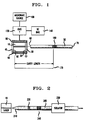
- FIG. 1 is a schematic, block diagram of the inventive optical source, in one embodiment.
- FIG. 2 is a schematic diagram of the inventive source in a currently preferred embodiment in which a substantial portion of the optical cavity lies within an optical fiber, and the DBR is formed in the fiber.
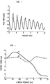
- FIG. 3 is a typical noise power spectrum of a cw laser system of the prior art, of the kind that includes a semiconductor diode laser and an external optical cavity terminated by a DBR. Spectral peaks indicating mode-beating noise are clearly visible in the spectrum.
- FIG. 4 is a graph of the effective lengths of two illustrative DBRs as functions of optical frequency.
- Curve A represents a DBR having an approximately linear chirp
- Curve B represents a DBR having a constant period.
- FIG. 1 A block diagram of an optical pulse source according to one aspect of the invention is shown in FIG. 1.
- Semiconductor diode laser 10 typically has a cleaved output facet 20 which is coated with antireflection coating 30.
- Laser 10 also typically includes cleaved back facet 40, which is optionally coated with high-reflectivity coating 45, or, alternatively, is left uncoated in order to provide a second output useful, e.g., for monitoring purposes.
- Waveguiding element 50 is optically coupled to facet 20 at proximal end 60, and optical pulses are extracted from element 50 at least at one distal end 70.
- the ac drive current for the laser is exemplarily delivered to the laser through contacts 80 and 90 from variable-frequency microwave source 100.
- a dc bias is provided from dc current source 140 by way of bias network 150.
- a distributed Bragg reflector (DBR) 160 is defined in a portion of element 50 intermediate ends 60 and 70.
- the DBR is formed by impressing a pattern of modulations of the effective refractive index of the waveguiding element. Specific embodiments will be discussed in greater detail below.
- Defined between facet 40 and DBR 160 is optical cavity 170. As is discussed below, the spatially distributed nature of the DBR results in an effective cavity length which depends, to a limited extent, upon the operating conditions of the pulse source.
- a strained quantum well laser operating, e.g., at about 1.55 ⁇ m.
- Such lasers are well-known to practitioners in the art, and are described, e.g., in T. Tanbun-Ek, et al., Appl. Phys. Lett. 57 , (1990) 2184.
- a round-trip time for optical pulses propagating therewithin.
- the multiplicative inverse of such round-trip time is referred to as the 'fundamental cavity frequency'.
- the laser is actively mode-locked by modulating the drive current at frequencies close to the fundamental cavity frequency.
- the performance of a mode-locked laser is very sensitive to the modulation frequency.
- the pulse width and the time-bandwidth product are generally believed to increase steeply as the modulation frequency is detuned away from the optimal frequency.
- the inventive optical pulse source has a surprisingly broad useful range of modulation frequencies. For example, in experiments, we have measured pulse widths of about 55 ps together with a time-bandwidth product of less than 0.5 over a bandwidth greater than 60 MHz, centered on a frequency of about 3.875 GHz. According to our current understanding, this effect is attributable to the spatially distributed nature of the Bragg reflector. That is, the distance to the effective reflection position within the reflector depends on wavelength.
- the effective length of the optical cavity may vary as the operating wavelength is varied. If the modulation frequency is changed, the center wavelength of the output spectrum shifts, and concomitantly, the effective cavity length also changes. Through such changes in the effective cavity length, the optical pulse source tends to self-adjust in such a way that resonance is maintained. For example, we have observed, in an experimental optical pulse source, a center wavelength of 1.5475 ⁇ m at modulation frequencies above 4.1 GHz. That is the same wavelength that the experimental device exhibited under dc operation. However, reducing the modulation frequency below 4.1 GHz caused the center wavelength to decrease. We observed a maximum wavelength shift of over 1 ⁇ for a modulation frequency change of 300 MHz.
- the waveguiding element is an optical fiber.
- FIG. 2 such an optical fiber 200 includes a lensed end 210 through which it is optically coupled to laser 10.
- Lensed optical fibers are well-known in the art, and are described, for example, in U.S. Patent No. 4,469,554, issued to D.R. Turner on September 4, 1984, and in U.S. Patent No. 4,932,989, issued to H.M. Presby on June 12, 1990.
- the lensed portion may be formed in a separate fiber stub, which is then readily attached to a distal fiber portion by means of fusion splice 220.
- the length of the optical cavity is primarily determined by the positioning of the grating. For that reason, it is desirable to position the grating with an accuracy of one millimeter or better, and preferable to position it with an accuracy of a few tenths of a millimeter. Such accuracy is readily achievable by a skilled practitioner.
- an optical isolator 230 is advantageously incorporated at a point distal DBR 240 for the purpose of preventing transmitted electromagnetic radiation from reflecting back into the laser.
- DBR 240 is typically formed by a photoinduced effect. That is, a permanent alteration in the refractive index of at least some silica-based glasses is effected by exposure to electromagnetic radiation, such as ultraviolet radiation.
- electromagnetic radiation such as ultraviolet radiation.
- alterations are readily made in a silica fiber having a germanium-doped core by exposure to radiation of wavelength 242 nm from, e.g., an excimer-pumped, frequency-doubled, tunable, dye laser.
- One commercially available optical fiber which is useful in that regard is manufactured by AT&T under the tradename ACCUTETHER 220.
- a series of interference fringes of radiation of the effective wavelength is readily produced with a periodicity appropriate for the DBR.
- the DBR is formed by exposure of an optical fiber to such an interference pattern.
- This technique is well-known in the art, and is described, for example, in U.S. Patent No. 4,725,110, issued to W.H. Glenn, et al., on Feb. 16, 1988.
- An external cavity laser which uses such a DBR, but is not mode-locked, is described in D.M. Bird, et al., 'Narrow Line Semiconductor Laser Using Fibre Grating', Electr. Lett. 27 (1991) 1115-1116.
- An optical pulse source having an optical fiber cavity was made substantially as described above.
- a single-mode fiber having a germanium-doped core and a lensed end was used.
- the cavity length was about 40 mm.
- the DBR was photoinduced substantially as described.
- the Bragg wavelength was 1.5328 ⁇ m.
- the measured reflectivity of the DBR had a peak value of 63% and a full width at half-maximum (FWHM) of 2.0 ⁇ .
- the physical length of the DBR (FWHM) was 5 mm.
- Active mode locking was performed at the optimal modulation frequency of 2.37 GHz and a bias level of 36 mA.
- the ac drive current was provided by delivering a signal, at a power level somewhat less than one watt, from a high-power, sinusoidal microwave source into a step recovery diode to produce an inverted, short-pulse waveform.
- the diode output was sent through an inverter to produce positive pulses, and the inverter output was applied to the laser.
- Mode-locked pulses were obtained having a full width at half-maximum of 18.5 ps, an optical bandwidth of 1.3 ⁇ (i.e., 16.7 GHz), and a time-bandwidth product of 0.31, which is at the transform limit for a sech-squared pulse shape.
- the threshold current of the laser was 11 milliamperes, and the peak optical power output was 49 mW.
- the inventive pulse source can exhibit self-tuning behavior. That is, the fundamental cavity frequency is inversely proportional to the effective optical length of the cavity. This length, in turn, depends on the operating wavelength. If the DBR has a constant period (i.e., the DBR is not chirped), the effective optical length will be somewhat longer for wavelengths slightly longer or shorter than the design wavelength of the DBR. The self-tuning behavior is observed when the modulation frequency is slightly lower than the fundamental cavity frequency corresponding to the design wavelength. In such cases, the operating wavelength may spontaneously increase or decrease by a small amount. As a consequence, the effective optical length of the cavity is increased, the fundamental cavity frequency is reduced to roughly the same value as the modulation frequency, and mode-locking is preserved.
- the optical output spectrum can exhibit instabilities. For example, we have observed, in some cases, a twin-lobed optical spectrum.
- a linearly chirped DBR can be used to assure that only one operating wavelength will correspond to a given modulation frequency.
- the Bragg condition will be satisfied only in a short segment of the grating. The longitudinal position of that segment will depend on the operating wavelength. In a rough sense, each possible operating wavelength will be reflected from a segment situated at a unique one of these longitudinal positions. Each of these positions will correspond to a unique value of the fundamental cavity frequency.
- the laser will self-tune by adopting that operating wavelength that gives a fundamental cavity frequency matched to the modulation frequency.
- chirped gratings are useful not only for stabilizing the operation of mode-locked lasers, but also for stabilizing continuously operating (cw) diode lasers. That is, the laser cavity is generally able to support a multiplicity of closely spaced, Fabry-Perot resonant modes. Ideally, only one of these modes experiences maximum gain, and the light emitted by a cw laser corresponds exclusively to this mode. However, it often happens in practice that substantial emission occurs in more than one mode. One undesirable consequence of this is so-called 'mode-beating noise', which causes the output optical power to fluctuate. Surprisingly, we have found that in at least some cases of continuous operation of laser 10, chirping of the DBR will reduce mode-beating noise below detectable limits.
- FIG. 3 is the noise power spectrum of the continuous optical emission from a laser system as described above, including a DBR having a constant period. Peaks at numerous, uniformly spaced beat frequencies are clearly visible. When we substituted a DBR having an approximately linear chirp, these peaks were completely eliminated.
- the chirped DBR was oriented such that the local Bragg wavelength was largest at the end proximal the diode laser, and smallest at the distal end. (In some cases, the reverse orientation may also be effective.)
- the strength of the DBR i.e., the magnitude of the quasiperiodic refractive index perturbations
- Curve A represents the chirped DBR
- Curve B represents a typical DBR having a constant period.
- the optical frequencies of FIG. 4 are referred to the wavelength of maximum reflectivity of a hypothetical DBR whose background refractive index is unaffected by the perturbations. (In a real DBR, the spatial average of these perturbations contributes to the effective background index. Often, this background contribution has a Gaussian profile, which may add a small quadratic component to the total chirp of the DBR.)
Landscapes
- Physics & Mathematics (AREA)
- Electromagnetism (AREA)
- Optics & Photonics (AREA)
- Condensed Matter Physics & Semiconductors (AREA)
- General Physics & Mathematics (AREA)
- Engineering & Computer Science (AREA)
- Computer Networks & Wireless Communication (AREA)
- Signal Processing (AREA)
- Semiconductor Lasers (AREA)
- Optical Communication System (AREA)
Applications Claiming Priority (2)
| Application Number | Priority Date | Filing Date | Title |
|---|---|---|---|
| US15664 | 1993-02-09 | ||
| US08/015,664 US5305336A (en) | 1992-01-29 | 1993-02-09 | Compact optical pulse source |
Publications (1)
| Publication Number | Publication Date |
|---|---|
| EP0611097A1 true EP0611097A1 (fr) | 1994-08-17 |
Family
ID=21772783
Family Applications (1)
| Application Number | Title | Priority Date | Filing Date |
|---|---|---|---|
| EP94300786A Withdrawn EP0611097A1 (fr) | 1993-02-09 | 1994-02-02 | Source optique compacte comprenant un laser |
Country Status (3)
| Country | Link |
|---|---|
| US (1) | US5305336A (fr) |
| EP (1) | EP0611097A1 (fr) |
| JP (1) | JPH06291423A (fr) |
Cited By (11)
| Publication number | Priority date | Publication date | Assignee | Title |
|---|---|---|---|---|
| US5771250A (en) * | 1995-11-01 | 1998-06-23 | Sumitomo Electric Indust., Ltd. | Laser light source apparatus, OTDR apparatus, and optical communication line inspection system |
| EP0797783A4 (fr) * | 1994-12-12 | 1998-09-02 | Uniphase Corp | Generateur optique non lineaire pourvu d'un agencement reflecteur a indice de refraction perturbe |
| EP0860917A3 (fr) * | 1997-02-21 | 1998-10-21 | Sumitomo Electric Industries, Ltd. | Module laser à semi-conducteur |
| US6067392A (en) * | 1995-10-16 | 2000-05-23 | Sumitomo Electric Industries, Ltd. | Optical fiber diffraction grating, a method of fabricating thereof and a laser light source |
| WO2000072416A1 (fr) * | 1999-05-25 | 2000-11-30 | Cirrex Corporation | Ensemble de retroaction optique |
| US6415082B1 (en) | 1999-03-15 | 2002-07-02 | Cirrex Corp. | Optical networking assembly |
| EP1087477A3 (fr) * | 1999-09-24 | 2002-07-24 | The Furukawa Electric Co., Ltd. | Module laser à semi-conducteur |
| US6542660B1 (en) | 1999-05-25 | 2003-04-01 | Cirrex Corp. | Method and system for increasing a number of information channels carried by optical waveguides |
| EP1610477A1 (fr) * | 2004-06-23 | 2005-12-28 | Alcatel | Émetteur optique micro-onde avec laser auto pulsant |
| US7565084B1 (en) | 2004-09-15 | 2009-07-21 | Wach Michael L | Robustly stabilizing laser systems |
| US7901870B1 (en) | 2004-05-12 | 2011-03-08 | Cirrex Systems Llc | Adjusting optical properties of optical thin films |
Families Citing this family (50)
| Publication number | Priority date | Publication date | Assignee | Title |
|---|---|---|---|---|
| US5712715A (en) * | 1992-12-23 | 1998-01-27 | Lucent Technologies Inc. | Optical transmission system with spatially-varying Bragg reflector |
| US5363239A (en) * | 1992-12-23 | 1994-11-08 | At&T Bell Laboratories | Method for forming spatially-varying distributed Bragg reflectors in optical media |
| ES2121194T3 (es) * | 1993-03-25 | 1998-11-16 | British Telecomm | Laser. |
| US5563732A (en) * | 1994-01-06 | 1996-10-08 | At&T Corp. | Laser pumping of erbium amplifier |
| AUPM386794A0 (en) * | 1994-02-14 | 1994-03-10 | University Of Sydney, The | Optical grating |
| FR2720198B1 (fr) * | 1994-05-20 | 1996-07-19 | France Telecom | Laser à fibre optique polarisé linéairement. |
| US5521738A (en) * | 1994-06-30 | 1996-05-28 | At&T Corp. | Data encoded optical pulse generator |
| US5633885A (en) * | 1994-09-29 | 1997-05-27 | Imra America, Inc. | Frequency chirp control and compensation for obtaining broad bandwidth ultrashort optical pulses from wavelength-tunable lasers |
| DE4441133A1 (de) * | 1994-11-21 | 1996-05-23 | Sel Alcatel Ag | Modengekoppelter Faserlaser |
| AUPN694795A0 (en) * | 1995-12-01 | 1996-01-04 | University Of Sydney, The | Distributed feedback ring laser |
| EP0784362B1 (fr) * | 1996-01-12 | 2003-03-26 | Corning O.T.I. S.p.A. | Laser DBR en niobate de lithium dopé par des terres rares |
| JP2000505599A (ja) | 1996-03-01 | 2000-05-09 | アグファ―ゲーベルト・アクチェンゲゼルシャフト | レーザーダイオードを使用する方法とその装置 |
| DE19607877A1 (de) * | 1996-03-01 | 1997-09-04 | Agfa Gevaert Ag | Verfahren und Vorrichtung zum Betrieb einer Laserdiode |
| AUPO761497A0 (en) * | 1997-06-27 | 1997-07-24 | University Of Sydney, The | Narrow transmission bandpass filters utilising bragg grating assisted mode conversion |
| AU9472298A (en) * | 1997-09-05 | 1999-03-22 | Micron Optics, Inc. | Tunable fiber fabry-perot surface-emitting lasers |
| DE19805553A1 (de) * | 1998-02-11 | 1999-08-19 | Ldt Gmbh & Co | Verfahren zur Intensitätssteuerung von Laserlicht und eine intensitätssteuerbare Laseranordnung |
| US6088376A (en) * | 1998-03-16 | 2000-07-11 | California Institute Of Technology | Vertical-cavity-surface-emitting semiconductor devices with fiber-coupled optical cavity |
| FR2781613B1 (fr) * | 1998-07-27 | 2000-10-06 | Photonetics | Laser en espace libre avec sortie fibre autoalignee |
| SE9803285L (sv) * | 1998-09-28 | 2000-03-29 | Imc Ind Mikroelektronikcentrum | Avstämbar laser jämte förfarande att avstämm densamma |
| AU6407699A (en) | 1998-11-06 | 2000-05-29 | Corning Incorporated | Athermal optical waveguide grating device |
| EP1603206A3 (fr) | 1999-02-03 | 2006-04-26 | The Furukawa Electric Co., Ltd. | Laser à semiconducteur et module de laser à semiconducteur utilisant ledit laser |
| US6810063B1 (en) | 1999-06-09 | 2004-10-26 | The Furukawa Electric Co., Ltd. | Semiconductor laser device |
| WO2001004999A1 (fr) | 1999-07-07 | 2001-01-18 | Cyoptics Ltd. | Stabilisation de la longueur d'onde d'un laser |
| TW440728B (en) * | 1999-11-04 | 2001-06-16 | Ind Tech Res Inst | A tunable fiber grating |
| EP1130718A3 (fr) * | 2000-01-20 | 2003-07-02 | Cyoptics (Israel) Ltd. | Laser stabilisé à fréquence accordable à réseau à fibre |
| US6870871B2 (en) | 2000-02-03 | 2005-03-22 | The Furukawa Electric Co., Ltd. | Semiconductor laser devices, and semiconductor laser modules and optical communication systems using the same |
| US6614822B2 (en) | 2000-02-03 | 2003-09-02 | The Furukawa Electric Co., Ltd. | Semiconductor laser devices, and semiconductor laser modules and optical communication systems using the same |
| US6466703B1 (en) | 2000-04-07 | 2002-10-15 | Hrl Laboratories, Llc | Method and apparatus for electro-optic delay generation of optical signals |
| US6374014B1 (en) * | 2000-04-17 | 2002-04-16 | Ciena Corporation | Fiber grating package |
| US6625182B1 (en) * | 2000-04-20 | 2003-09-23 | Corning Incorporated | Semiconductor or solid-state laser having an external fiber cavity |
| US6647048B2 (en) * | 2000-04-28 | 2003-11-11 | Photodigm, Inc. | Grating-outcoupled surface-emitting lasers using quantum wells with thickness and composition variation |
| JP2002111135A (ja) | 2000-10-02 | 2002-04-12 | Furukawa Electric Co Ltd:The | 半導体レーザ素子、それを用いた光ファイバ増幅器用励起光源 |
| US6714575B2 (en) * | 2001-03-05 | 2004-03-30 | Photodigm, Inc. | Optical modulator system |
| US6816518B2 (en) | 2001-03-20 | 2004-11-09 | Cyoptics (Israel) Ltd. | Wavelength tunable high repetition rate optical pulse generator |
| WO2002103867A1 (fr) | 2001-06-15 | 2002-12-27 | Infineon Technologies Ag | Module laser optoelectronique |
| US6517296B2 (en) * | 2001-06-21 | 2003-02-11 | Vernon Devices, Inc. | Hole finishing tool |
| US6862136B2 (en) | 2002-01-31 | 2005-03-01 | Cyoptics Ltd. | Hybrid optical transmitter with electroabsorption modulator and semiconductor optical amplifier |
| US7463661B2 (en) * | 2002-02-27 | 2008-12-09 | National Institute Of Advanced Industrial Science And Technology | Quantum nano-structure semiconductor laser |
| FR2840119A1 (fr) * | 2002-05-27 | 2003-11-28 | Cit Alcatel | Dispositif laser auto-pulsant a reflecteur de bragg distribue a pas variable |
| US6973106B1 (en) | 2002-10-11 | 2005-12-06 | Corvis Corporation | Optical package and optical systems apparatuses, and methods of use therein |
| EP1558955A4 (fr) * | 2002-10-15 | 2006-04-19 | Micron Optics Inc | Filtres fabry-perot a fibre sans plaquette |
| WO2004059357A1 (fr) * | 2002-12-20 | 2004-07-15 | Micron Optics, Inc. | Support de ferrule a compensation thermique pour un filtre fabry-perot a fibre |
| US20040201100A1 (en) * | 2003-04-14 | 2004-10-14 | Desmond Lim | Integrated optical receiver |
| US20050238068A1 (en) * | 2004-04-27 | 2005-10-27 | Suning Tang | Frequency tunable optical RF source |
| US7725043B2 (en) * | 2004-10-07 | 2010-05-25 | Raytheon Company | System and method for reducing interferometric distortion and relative intensity noise in directly modulated fiber optic links |
| US7430376B1 (en) | 2004-11-29 | 2008-09-30 | Hrl Laboratories, Llc | All-optical delay generator for PPM communication systems based on a non-linear waveguide with a chirped DBR |
| GB2477740B (en) * | 2010-02-10 | 2014-06-25 | Oclaro Technology Ltd | Reduced length optoelectronic devices |
| US9479280B2 (en) * | 2011-07-14 | 2016-10-25 | Applied Optoelectronics, Inc. | Extended cavity fabry-perot laser assembly capable of high speed optical modulation with narrow mode spacing and WDM optical system including same |
| US9160455B2 (en) | 2011-07-14 | 2015-10-13 | Applied Optoelectronics, Inc. | External cavity laser array system and WDM optical system including same |
| CN113614632B (zh) * | 2019-05-09 | 2025-08-01 | 松下知识产权经营株式会社 | 光设备及光检测系统 |
Citations (2)
| Publication number | Priority date | Publication date | Assignee | Title |
|---|---|---|---|---|
| GB2178591A (en) * | 1985-07-25 | 1987-02-11 | Plessey Co Plc | Laser feedback system |
| US5091916A (en) * | 1990-09-28 | 1992-02-25 | At&T Bell Laboratories | Distributed reflector laser having improved side mode suppression |
Family Cites Families (8)
| Publication number | Priority date | Publication date | Assignee | Title |
|---|---|---|---|---|
| US4469554A (en) * | 1983-04-05 | 1984-09-04 | At&T Bell Laboratories | Etch procedure for optical fibers |
| EP0191063B1 (fr) * | 1984-08-13 | 1992-05-13 | United Technologies Corporation | Procede d'impression de reseaux dans des fibres optiques |
| US5058977A (en) * | 1987-01-20 | 1991-10-22 | Hewlett-Packard Company | Broadband tunable in-line filter for fiber optics |
| US4786132A (en) * | 1987-03-31 | 1988-11-22 | Lytel Corporation | Hybrid distributed bragg reflector laser |
| US4955028A (en) * | 1988-03-25 | 1990-09-04 | At&T Bell Laboratories | Wavelength tunable composite cavity laser |
| US4932989A (en) * | 1989-04-05 | 1990-06-12 | At&T Bell Laboratories | Method and apparatus for fabricating microlenses on optical fibers |
| JPH03263010A (ja) * | 1990-03-14 | 1991-11-22 | Fujitsu Ltd | ファイバ型ブラッグ反射器 |
| JPH0777279B2 (ja) * | 1990-07-27 | 1995-08-16 | パイオニア株式会社 | 光パルス発生装置 |
-
1993
- 1993-02-09 US US08/015,664 patent/US5305336A/en not_active Expired - Lifetime
-
1994
- 1994-02-02 EP EP94300786A patent/EP0611097A1/fr not_active Withdrawn
- 1994-02-09 JP JP6035218A patent/JPH06291423A/ja active Pending
Patent Citations (2)
| Publication number | Priority date | Publication date | Assignee | Title |
|---|---|---|---|---|
| GB2178591A (en) * | 1985-07-25 | 1987-02-11 | Plessey Co Plc | Laser feedback system |
| US5091916A (en) * | 1990-09-28 | 1992-02-25 | At&T Bell Laboratories | Distributed reflector laser having improved side mode suppression |
Non-Patent Citations (3)
| Title |
|---|
| P.A. MORTON ET AL.: "Hybrid Soliton Pulse Source Using a Silica Waveguide External Cavity and Bragg Reflector", APPLIED PHYSICS LETTERS, vol. 59, no. 23, 2 December 1991 (1991-12-02), NEW YORK, US, pages 2944 - 2946, XP000261439 * |
| P.A. MORTON ET AL.: "Mode-Locked Hybrid Soliton Pulse Source with Extremly Wide Operating Frequency Range", IEEE PHOTONICS TECHNOLOGY LETTERS, vol. 5, no. 1, January 1993 (1993-01-01), NEW YORK, US, pages 28 - 31, XP000335389 * |
| P.A.MORTON ET AL.: "Hybrid Soliton Pulse Source with Fibre External Cavity and Bragg Reflector", ELECTRONICS LETTERS, vol. 28, no. 6, 12 March 1992 (1992-03-12), STEVENAGE, GB, pages 561 - 562, XP000287239 * |
Cited By (19)
| Publication number | Priority date | Publication date | Assignee | Title |
|---|---|---|---|---|
| EP0797783A4 (fr) * | 1994-12-12 | 1998-09-02 | Uniphase Corp | Generateur optique non lineaire pourvu d'un agencement reflecteur a indice de refraction perturbe |
| US6067392A (en) * | 1995-10-16 | 2000-05-23 | Sumitomo Electric Industries, Ltd. | Optical fiber diffraction grating, a method of fabricating thereof and a laser light source |
| US5771250A (en) * | 1995-11-01 | 1998-06-23 | Sumitomo Electric Indust., Ltd. | Laser light source apparatus, OTDR apparatus, and optical communication line inspection system |
| EP0860917A3 (fr) * | 1997-02-21 | 1998-10-21 | Sumitomo Electric Industries, Ltd. | Module laser à semi-conducteur |
| US5993073A (en) * | 1997-02-21 | 1999-11-30 | Sumitomo Electric Industries, Ltd. | Semiconductor laser module |
| US6415082B1 (en) | 1999-03-15 | 2002-07-02 | Cirrex Corp. | Optical networking assembly |
| US6496523B1 (en) | 1999-05-25 | 2002-12-17 | Cirrex Corp. | Optical feedback assembly |
| WO2000072416A1 (fr) * | 1999-05-25 | 2000-11-30 | Cirrex Corporation | Ensemble de retroaction optique |
| US6542660B1 (en) | 1999-05-25 | 2003-04-01 | Cirrex Corp. | Method and system for increasing a number of information channels carried by optical waveguides |
| EP1087477A3 (fr) * | 1999-09-24 | 2002-07-24 | The Furukawa Electric Co., Ltd. | Module laser à semi-conducteur |
| US6524016B1 (en) | 1999-09-24 | 2003-02-25 | The Furukawa Electric Co., Ltd. | Semiconductor laser module |
| US7901870B1 (en) | 2004-05-12 | 2011-03-08 | Cirrex Systems Llc | Adjusting optical properties of optical thin films |
| US8986922B1 (en) | 2004-05-12 | 2015-03-24 | Cirrex Systems, Llc | Adjusting optical properties of optical thin films |
| EP1610477A1 (fr) * | 2004-06-23 | 2005-12-28 | Alcatel | Émetteur optique micro-onde avec laser auto pulsant |
| FR2872359A1 (fr) * | 2004-06-23 | 2005-12-30 | Alcatel Sa | Emetteur optique micro-onde avec laser auto pulsant |
| US7565084B1 (en) | 2004-09-15 | 2009-07-21 | Wach Michael L | Robustly stabilizing laser systems |
| US7965949B1 (en) | 2004-09-15 | 2011-06-21 | Cirrex Systems Llc | Robustly stabilizing laser systems |
| US8521038B1 (en) | 2004-09-15 | 2013-08-27 | Cirrex Systems, Llc | Robustly stabilizing laser systems |
| US9065572B1 (en) | 2004-09-15 | 2015-06-23 | Cirrex Systems, Llc | Robustly stabilizing laser systems |
Also Published As
| Publication number | Publication date |
|---|---|
| JPH06291423A (ja) | 1994-10-18 |
| US5305336A (en) | 1994-04-19 |
Similar Documents
| Publication | Publication Date | Title |
|---|---|---|
| EP0611097A1 (fr) | Source optique compacte comprenant un laser | |
| US6240119B1 (en) | Apparatus for providing a stabilized laser source | |
| EP0829740B1 (fr) | Réseau de guide d'onde pour le couplage de modes | |
| EP0208189B1 (fr) | Laser à fibre optique | |
| US6373867B1 (en) | Generation of a wavelength-tunable laser oscillation in a wave-guiding gain medium based on passive mode lock | |
| EP0812484B1 (fr) | Source laser a fibre a emission polarisee | |
| Morton et al. | Mode-locked hybrid soliton pulse source with extremely wide operating frequency range | |
| US5305335A (en) | Single longitudinal mode pumped optical waveguide laser arrangement | |
| EP0523084B1 (fr) | Procede de formation d'un reseau d'indice de refraction dans un guide d'ondes optique | |
| Sato et al. | Chirp-compensated 40-GHz mode-locked lasers integrated with electroabsorption modulators and chirped gratings | |
| US20090290613A1 (en) | External cavity laser assembly including external chirped exit reflector for improved linearity | |
| US9190799B2 (en) | Q-switched all-fiber laser | |
| Eisenstein et al. | Active mode-locking characteristics of InGaAsP-single mode fiber composite cavity lasers | |
| Morton et al. | Hybrid soliton pulse source with fibre external cavity and Bragg reflector | |
| Ibsen et al. | Robust high power (> 20 mW) all-fibre DFB lasers with unidirectional and truly single polarisation outputs | |
| JPH0449793B2 (fr) | ||
| EP1343227B1 (fr) | Génération de signaux électroniques porteurs dans le domaine optique | |
| US20050053101A1 (en) | Mode selection for single frequency fiber laser | |
| US6075805A (en) | Apparatus for linewidth reduction in distributed feedback or distributed Bragg reflector semiconductor lasers using vertical emission | |
| CA2524911A1 (fr) | Laser a semi-conducteurs a modulation du facteur q avec structures en reseau a electroabsorption | |
| Morton et al. | Packaged hybrid soliton pulse source results 70 terabit. km/sec soliton transmission | |
| JP3444464B2 (ja) | 短パルス光源 | |
| EP0553994A1 (fr) | Source compacte d'impulsions optiques | |
| US6813305B2 (en) | Method and apparatus for optical wavelength conversion | |
| EP0742618A2 (fr) | Laser à double guide d'ondes asymétrique |
Legal Events
| Date | Code | Title | Description |
|---|---|---|---|
| PUAI | Public reference made under article 153(3) epc to a published international application that has entered the european phase |
Free format text: ORIGINAL CODE: 0009012 |
|
| AK | Designated contracting states |
Kind code of ref document: A1 Designated state(s): DE FR GB |
|
| 17P | Request for examination filed |
Effective date: 19950202 |
|
| 17Q | First examination report despatched |
Effective date: 19951227 |
|
| STAA | Information on the status of an ep patent application or granted ep patent |
Free format text: STATUS: THE APPLICATION IS DEEMED TO BE WITHDRAWN |
|
| 18D | Application deemed to be withdrawn |
Effective date: 19960709 |