EP0611171A1 - Synchronisationssystem für redundante Aufträge - Google Patents
Synchronisationssystem für redundante Aufträge Download PDFInfo
- Publication number
- EP0611171A1 EP0611171A1 EP94400025A EP94400025A EP0611171A1 EP 0611171 A1 EP0611171 A1 EP 0611171A1 EP 94400025 A EP94400025 A EP 94400025A EP 94400025 A EP94400025 A EP 94400025A EP 0611171 A1 EP0611171 A1 EP 0611171A1
- Authority
- EP
- European Patent Office
- Prior art keywords
- messages
- redundant
- message
- tasks
- task
- Prior art date
- Legal status (The legal status is an assumption and is not a legal conclusion. Google has not performed a legal analysis and makes no representation as to the accuracy of the status listed.)
- Granted
Links
Images

Classifications
-
- G—PHYSICS
- G06—COMPUTING OR CALCULATING; COUNTING
- G06F—ELECTRIC DIGITAL DATA PROCESSING
- G06F11/00—Error detection; Error correction; Monitoring
- G06F11/07—Responding to the occurrence of a fault, e.g. fault tolerance
- G06F11/16—Error detection or correction of the data by redundancy in hardware
- G06F11/20—Error detection or correction of the data by redundancy in hardware using active fault-masking, e.g. by switching out faulty elements or by switching in spare elements
- G06F11/2097—Error detection or correction of the data by redundancy in hardware using active fault-masking, e.g. by switching out faulty elements or by switching in spare elements maintaining the standby controller/processing unit updated
-
- G—PHYSICS
- G05—CONTROLLING; REGULATING
- G05B—CONTROL OR REGULATING SYSTEMS IN GENERAL; FUNCTIONAL ELEMENTS OF SUCH SYSTEMS; MONITORING OR TESTING ARRANGEMENTS FOR SUCH SYSTEMS OR ELEMENTS
- G05B19/00—Program-control systems
- G05B19/02—Program-control systems electric
- G05B19/418—Total factory control, i.e. centrally controlling a plurality of machines, e.g. direct or distributed numerical control [DNC], flexible manufacturing systems [FMS], integrated manufacturing systems [IMS] or computer integrated manufacturing [CIM]
- G05B19/41865—Total factory control, i.e. centrally controlling a plurality of machines, e.g. direct or distributed numerical control [DNC], flexible manufacturing systems [FMS], integrated manufacturing systems [IMS] or computer integrated manufacturing [CIM] characterised by job scheduling, process planning, material flow
-
- G—PHYSICS
- G05—CONTROLLING; REGULATING
- G05B—CONTROL OR REGULATING SYSTEMS IN GENERAL; FUNCTIONAL ELEMENTS OF SUCH SYSTEMS; MONITORING OR TESTING ARRANGEMENTS FOR SUCH SYSTEMS OR ELEMENTS
- G05B9/00—Safety arrangements
- G05B9/02—Safety arrangements electric
- G05B9/03—Safety arrangements electric with multiple-channel loop, i.e. redundant control systems
-
- Y—GENERAL TAGGING OF NEW TECHNOLOGICAL DEVELOPMENTS; GENERAL TAGGING OF CROSS-SECTIONAL TECHNOLOGIES SPANNING OVER SEVERAL SECTIONS OF THE IPC; TECHNICAL SUBJECTS COVERED BY FORMER USPC CROSS-REFERENCE ART COLLECTIONS [XRACs] AND DIGESTS
- Y02—TECHNOLOGIES OR APPLICATIONS FOR MITIGATION OR ADAPTATION AGAINST CLIMATE CHANGE
- Y02P—CLIMATE CHANGE MITIGATION TECHNOLOGIES IN THE PRODUCTION OR PROCESSING OF GOODS
- Y02P90/00—Enabling technologies with a potential contribution to greenhouse gas [GHG] emissions mitigation
- Y02P90/02—Total factory control, e.g. smart factories, flexible manufacturing systems [FMS] or integrated manufacturing systems [IMS]
Definitions
- a method of operating a data processing system adapted to execute two or more redundant tasks receiving identical data in parallel, in which messages, each including such data and a time stamp, is transferred to redundant tasks, the messages transferred to each redundant task being ordered in chronological order to be processed by the redundant task in this order and a stability date is determined for each message, this stability date defining the moment from which the task redundant can process the message.
- the invention applies more particularly to the synchronization of redundant tasks residing in automation control computers (level 1 of the CIM model) of an industrial control / command installation.
- Redundancy on redundant task inputs is a known technique for implementing fault tolerance procedures. Redundant tasks take the same data as input and execute the same program so that switching of the output of redundant tasks is possible if one of them fails. We consider here only redundant tasks reacting only to the input data (which are generally provided by tasks transmitting such data which reside in other processors). To have active redundancy, it is necessary that the redundant tasks have the same behavior. This is achieved by arranging so that the redundant tasks take their input data in the same chronological order, i.e. are synchronized.
- processors in which the redundant tasks reside also have a local clock and the clocks of all the processors are possibly resynchronized, as is well known, in order to maintain an identical time reference from one processor to another.
- "Fault-Tolerant Clock Synchronization in Distributed Systems-COMPUTER-IEEE-October 1990” describes synchronization procedures n of processor clocks.
- a single time constant is determined beforehand, from the data transfer times measured between each sending task and each redundant task.
- the time constant is equal to the maximum of these measured transfer times.
- Messages received by a second processor are placed in a queue where they are ordered in ascending order of their time stamp.
- a stability date, for each message is calculated, this date being equal to the total of the time stamp and the time constant.
- a message at the input of a processor is said to be stable when no other message having a stamp lower than that of this message can no longer arrive at the input of the processor. Consequently a stable message is detected when the clock of the second processor gives a date greater than the stability date of the message. This is then taken from the queue and the data it contains is supplied to the redundant task residing in this second processor.
- This process is performed in the same way on the other second processor.
- the redundant tasks take into account the data they receive according to an identical chronology given by the time stamps of the messages encapsulating this data.
- This known synchronization system has the following drawback.
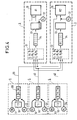
- a control / command installation is shown diagrammatically and comprises a control station 1 (PC) (level 2 of the CIM model) connected, through a network 2 for transmitting messages supporting a communication protocol by aperiodic example, to automation control computers 3 (CA1, CA2).
- the automation control computers 3 are connected, through a network 4 for transmitting messages supporting a communication protocol, for example periodic, to remote interfaces 5 (E / S1, E / S2) which receive data or transmit data to a physical process 6 to be checked.
- the data processing process connecting the remote interfaces to the automation control computers is real time.
- the characteristics of networks 2 and 4 are such that the transmission times of messages between the remote interfaces 5 and the processors 3 are much lower than the transmission times of messages between the driving station 1 and the computers 3.
- Document EP-A-0445954 also discloses a system for synchronizing concurrent tasks which is based on the use of virtual time stamps (counters). With this known system, the stability dates of the messages are not taken into account.
- the object of the invention is to remedy the aforementioned drawbacks with a view to favoring the processing of certain messages over others while maintaining perfect synchronization of processing of messages between redundant tasks.
- the subject of the invention is a method of operating a data processing system adapted to execute in parallel two or more redundant tasks receiving identical data, in which messages including each of such data and a time stamp are transferred to the redundant tasks, the messages transferred to each redundant task being ordered in chronological order to be processed by the redundant task in this order and a stability date is determined for each message, this stability date defining the instant from which the redundant task can process the message, characterized in that the scheduling of the messages transferred to a redundant task is based on the time stamps of the messages increased respectively by first time constants and the stability dates of the messages are determined on the basis of the timestamps of these messages increased respectively by second time constants.
- each message there is included in each message a code identifying the source of the message which may be a sending task.
- the method according to the invention ensures that the waiting time for messages from priority tasks is reduced to the maximum. If there is only one priority sending task, the messages for this task have zero waiting time for their processing by the redundant tasks. In addition, the waiting times for messages for tasks that send messages and are not priority are equal to each other and reduced to the minimum.
- FIG. 1 represents a control / command installation.
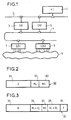
- Figure 2 shows the structure of a message.
- Figure 3 shows a record in a message queue.
- FIG. 4 represents, in the form of functional blocks, the task synchronization system according to the invention for the control / command installation of FIG. 1.
- Figure 5 is a flowchart illustrating one way to implement stable message detection for the synchronization system.
- each remote interface 5 conventionally consists of a processor with memory and peripheral equipment. They each have a local clock 52,54.
- a task T1 transmitting data D bearing the reference 10 resides in the driving position 1.
- the driving position consists of a processor with memory and peripheral equipment. It also has a local clock 12.
- Each automation control computer 3 also consists of a processor with memory and peripheral. They each include a local clock 32.
- These output interface tasks are coupled to the transmitting tasks via data input / output queues (not shown) to ensure the passage of data over the 2.4 networks to the computers 3. In this way, the structure and the operation of the transmitting tasks are independent of the synchronization of the redundant tasks.
- each message 60 comprises a data zone 61 in which is written a data D supplied by a transmitting task, a zone 62 in which is written the date HL constituting a timestamp given by a local clock 12,52,54 at the time of the formation of the message and an area 63 in which a task or site identification code NS is registered.
- Each output interface task codes the messages it forms according to the appropriate communication protocol to send them on networks 20 and 40.
- the message identification code is a numerical value.
- the messages formed at the output of task T1 have an identification code equal to 1.
- the messages formed at the output of task T2 have an identification code equal to 2 and the messages formed at the output of task T3 have an identification code equal to 3.
- the messages 60 can be easily differentiated according to their respective origins.
- the redundant task synchronization system R1, R2 then comprises input interface tasks distributed in the computers 3.
- Each input interface task has the function of entering the messages 60 received by a computer 3, possibly delaying the messages received in a queue 33 and supply the data encapsulated in the messages to the redundant task 30 when the messages are stable.
- This input interface task uses time constants precalculated and recorded in memory or calculated online in the computer 3 to determine the date of stability of the messages and the order of taking into account of the data supplied to the redundant task 30.
- m1, m2, m3 are the minimum transfer times of data D between tasks T1, T2, T3 and task R1.
- M1, M2, M3 are the maximum transfer times of a data D between tasks T1, T2, T3 and task R1.
- a transfer time is equal to the difference between the local date of reception of data by a task 30 in a processor 3 and the local date of transmission of this data by a task 10.50 in a processor 1.5.
- R1, R2, R3 respectively for tasks T1, T2, T3 from the following relation, in which the indices i and j range from 1 to 3.
- R i max (M j - VS j ) + C i , i # i
- the time constants C1, C2, C3 and R1, R2, R3 are previously recorded in the computer 3 to be selectively retrieved from an identification code.
- the values m k and M k of the measured transfer times are recorded in the computer 3 in order to be recovered selectively from an identification code, the calculation of the time constants C and R being done online.
- Each record 34 comprises a field 35 in which is entered the data D of a message, a field 36 in which is inscribed the stamp HL of the message increased by the constant Cj whose index j corresponds to or is equal to the identification code NS of the message , a field 37 in which is inscribed the identification code NS of the message, a field 38 in which is inscribed the stamp value HL of the message increased by the time constant R j whose index j corresponds to or is equal to NS identification code of the message, and a field 39 in which a Boolean control variable F positioned at "False" is written.
- the value of field 38 of a record corresponds to the stability date of a message.
- Boolean constants B are recorded in the computer 3 in correspondence with the identification codes.
- the value of the Boolean constant is "True” if: max (M j - VS j ) - (m i - VS i )> 0 for j # i
- the expression max (M j - C j )) (m i - C i ) gives the maximum waiting time for a piece of data in a message waiting to be stable. Otherwise, this waiting time is zero.
- the messages 60 passing through the networks 2 and 4 are received in sequence at the input of the automation control computer 3 by the input interface task.
- a message 60 received is decoded at 100 to recover the data D, the stamp HL and the identification code NS of the message.
- the time constants Cj, Rj and the Boolean constant Bj whose index j corresponds to the identification code NS are retrieved at 110.
- the Boolean constant Bj is compared to the value "True" in 120. If it is not equal to "True”, the data D of the received message is supplied directly to the redundant task R1 in 130 since this message is stable. Otherwise, a record 34 is formed from the message 60 at 140 and is placed in the queue 33 so that the records 34 are ordered in ascending order of the field values 36. If two Consecutive records in queue 33 have the same field value 36, the one with the lowest field value 37 precedes the other in the queue.
- the records 34 in the queue 33 are scanned at 150.
- the control variable F in the field 39 is compared with the value "True” at 160. If this control variable is equal to "True”, processing continues at 150 for the next record 34 until all of the records have been scanned. Otherwise, the stability date in field 38 for the scanned record is compared in 170 with the current date supplied by the local clock 32 of the automation control computer 3. If this stability date is less than the current date, the control variable F of the field 39 is positioned to "True” in 180 and the processing continues in 150 and otherwise in 150. When all the records 34 have been scanned in the queue 33, the processing continues in 190.
- Steps 100 to 190 are repeated for each new message 63 received as input for this automation control computer.
- the input interface task described above works in the same way for the other redundant task residing in the other automation control computer, the time constants only having to be adapted to the data transfer times for this computer. .
- the invention can therefore easily be applied to a number of automation control computers and redundant tasks greater than 2.
Landscapes
- Engineering & Computer Science (AREA)
- Physics & Mathematics (AREA)
- General Physics & Mathematics (AREA)
- Automation & Control Theory (AREA)
- General Engineering & Computer Science (AREA)
- Quality & Reliability (AREA)
- Theoretical Computer Science (AREA)
- Manufacturing & Machinery (AREA)
- Hardware Redundancy (AREA)
- Multi Processors (AREA)
- Computer And Data Communications (AREA)
Applications Claiming Priority (2)
| Application Number | Priority Date | Filing Date | Title |
|---|---|---|---|
| FR9300147 | 1993-01-08 | ||
| FR9300147A FR2700401B1 (fr) | 1993-01-08 | 1993-01-08 | Système de synchronisation de tâches répondantes. |
Publications (2)
| Publication Number | Publication Date |
|---|---|
| EP0611171A1 true EP0611171A1 (de) | 1994-08-17 |
| EP0611171B1 EP0611171B1 (de) | 1998-03-25 |
Family
ID=9442913
Family Applications (1)
| Application Number | Title | Priority Date | Filing Date |
|---|---|---|---|
| EP94400025A Expired - Lifetime EP0611171B1 (de) | 1993-01-08 | 1994-01-05 | Synchronisationssystem für redundante Aufträge |
Country Status (6)
| Country | Link |
|---|---|
| US (1) | US5551034A (de) |
| EP (1) | EP0611171B1 (de) |
| JP (1) | JPH06242980A (de) |
| DE (1) | DE69409142T2 (de) |
| ES (1) | ES2115888T3 (de) |
| FR (1) | FR2700401B1 (de) |
Cited By (3)
| Publication number | Priority date | Publication date | Assignee | Title |
|---|---|---|---|---|
| EP0754991A1 (de) * | 1995-07-20 | 1997-01-22 | Raytheon Company | Fehlertolerantes verteiltes Steuerungssystem |
| EP0777355A1 (de) * | 1995-12-01 | 1997-06-04 | Sextant Avionique | Sichere Datenübertragung zur Prozessausführung mit dem ARINC 629 Protokoll |
| EP1239369A1 (de) * | 2001-03-07 | 2002-09-11 | Siemens Aktiengesellschaft | Fehlertolerante Rechneranordnung und Verfahren zum Betrieb einer derartigen Anordnung |
Families Citing this family (18)
| Publication number | Priority date | Publication date | Assignee | Title |
|---|---|---|---|---|
| US6412017B1 (en) * | 1996-07-01 | 2002-06-25 | Microsoft Corporation | Urgent replication facility |
| US6049809A (en) * | 1996-10-30 | 2000-04-11 | Microsoft Corporation | Replication optimization system and method |
| US6826752B1 (en) | 1998-12-17 | 2004-11-30 | California Institute Of Technology | Programming system and thread synchronization mechanisms for the development of selectively sequential and multithreaded computer programs |
| WO2000036491A2 (en) * | 1998-12-17 | 2000-06-22 | California Institute Of Technology | Programming system and thread synchronization mechanisms for the development of selectively sequential and multithreaded computer programs |
| US6470462B1 (en) * | 1999-02-25 | 2002-10-22 | Telefonaktiebolaget Lm Ericsson (Publ) | Simultaneous resynchronization by command for state machines in redundant systems |
| DE10002522C1 (de) * | 2000-01-21 | 2001-05-31 | Siemens Ag | Verfahren zur Bereitstellung von konsistenten Eingangswerten und Mehrrechnersystem |
| EP1162540A1 (de) * | 2000-06-07 | 2001-12-12 | Siemens Schweiz AG | Vorrichtung und Verfahren zur Synchronisation eines Systems von gekoppelten Datenverarbeitungsanlagen |
| US6819960B1 (en) | 2001-08-13 | 2004-11-16 | Rockwell Software Inc. | Industrial controller automation interface |
| GB2387683B (en) * | 2002-04-19 | 2007-03-28 | Hewlett Packard Co | Workflow processing scheduler |
| WO2012003862A1 (de) * | 2010-07-06 | 2012-01-12 | Siemens Aktiengesellschaft | Einrichtung zur synchronisierung von zwei prozessen eines redundanten steuerungssystems einer industriellen automatisierungsanordnung |
| EP2701065B1 (de) * | 2012-08-24 | 2015-02-25 | Siemens Aktiengesellschaft | Verfahren zum Betreiben eines redundanten Automatisierungssystems |
| WO2016067420A1 (ja) * | 2014-10-30 | 2016-05-06 | 三菱電機株式会社 | 計算機及びデータ処理方法及びプログラム |
| US10230670B1 (en) | 2014-11-10 | 2019-03-12 | Google Llc | Watermark-based message queue |
| JP6614373B1 (ja) * | 2019-02-13 | 2019-12-04 | 富士通クライアントコンピューティング株式会社 | 推論処理システム、推論処理装置及びプログラム |
| US11349917B2 (en) | 2020-07-23 | 2022-05-31 | Pure Storage, Inc. | Replication handling among distinct networks |
| US11442652B1 (en) | 2020-07-23 | 2022-09-13 | Pure Storage, Inc. | Replication handling during storage system transportation |
| US11321351B2 (en) * | 2020-09-08 | 2022-05-03 | International Business Machines Corporation | Adaptable legacy stateful workload |
| FR3130410B1 (fr) * | 2021-12-14 | 2023-12-15 | Atos Worldgrid | Système pour la conduite et l’aide à la conduite d’un processus industriel critique et procédé associé |
Citations (2)
| Publication number | Priority date | Publication date | Assignee | Title |
|---|---|---|---|---|
| EP0445954A2 (de) * | 1990-03-05 | 1991-09-11 | International Business Machines Corporation | Synchronisierung nebeneinander laufender Prozesse in einem Rechnersystem |
| US5168443A (en) * | 1990-09-26 | 1992-12-01 | Honeywell Inc. | Method for providing redundancy of a high speed pulse input I/O processor |
Family Cites Families (2)
| Publication number | Priority date | Publication date | Assignee | Title |
|---|---|---|---|---|
| US4577272A (en) * | 1983-06-27 | 1986-03-18 | E-Systems, Inc. | Fault tolerant and load sharing processing system |
| US4805107A (en) * | 1987-04-15 | 1989-02-14 | Allied-Signal Inc. | Task scheduler for a fault tolerant multiple node processing system |
-
1993
- 1993-01-08 FR FR9300147A patent/FR2700401B1/fr not_active Expired - Fee Related
-
1994
- 1994-01-05 EP EP94400025A patent/EP0611171B1/de not_active Expired - Lifetime
- 1994-01-05 DE DE69409142T patent/DE69409142T2/de not_active Expired - Fee Related
- 1994-01-05 ES ES94400025T patent/ES2115888T3/es not_active Expired - Lifetime
- 1994-01-07 US US08/178,886 patent/US5551034A/en not_active Expired - Lifetime
- 1994-01-07 JP JP6000592A patent/JPH06242980A/ja active Pending
Patent Citations (2)
| Publication number | Priority date | Publication date | Assignee | Title |
|---|---|---|---|---|
| EP0445954A2 (de) * | 1990-03-05 | 1991-09-11 | International Business Machines Corporation | Synchronisierung nebeneinander laufender Prozesse in einem Rechnersystem |
| US5168443A (en) * | 1990-09-26 | 1992-12-01 | Honeywell Inc. | Method for providing redundancy of a high speed pulse input I/O processor |
Non-Patent Citations (1)
| Title |
|---|
| K. G. SHIN ET AL.: "Fault-tolerant clock synchronization in distributed systems", COMPUTER, vol. 23, no. 10, October 1990 (1990-10-01), LOS ALAMITOS, pages 33 - 42 * |
Cited By (9)
| Publication number | Priority date | Publication date | Assignee | Title |
|---|---|---|---|---|
| EP0754991A1 (de) * | 1995-07-20 | 1997-01-22 | Raytheon Company | Fehlertolerantes verteiltes Steuerungssystem |
| EP0777355A1 (de) * | 1995-12-01 | 1997-06-04 | Sextant Avionique | Sichere Datenübertragung zur Prozessausführung mit dem ARINC 629 Protokoll |
| FR2742015A1 (fr) * | 1995-12-01 | 1997-06-06 | Sextant Avionique | Procede de securisation d'une action et dispositif de mise en oeuvre |
| US5872827A (en) * | 1995-12-01 | 1999-02-16 | Sextant Avionique | Method for producing a result and device for the implementation thereof |
| EP1239369A1 (de) * | 2001-03-07 | 2002-09-11 | Siemens Aktiengesellschaft | Fehlertolerante Rechneranordnung und Verfahren zum Betrieb einer derartigen Anordnung |
| WO2002071223A1 (de) * | 2001-03-07 | 2002-09-12 | Siemens Aktiengesellschaft | Fehlertolerante rechneranordnung und verfahren zum betrieb einer derartigen anordnung |
| AU2002246102B2 (en) * | 2001-03-07 | 2005-04-14 | Siemens Aktiengesellschaft | Fault-tolerant computer cluster and a method for operating a cluster of this type |
| AU2002246102B9 (en) * | 2001-03-07 | 2005-04-21 | Siemens Aktiengesellschaft | Fault-tolerant computer cluster and a method for operating a cluster of this type |
| US7260740B2 (en) | 2001-03-07 | 2007-08-21 | Siemens Aktiengesellshcaft | Fault-tolerant computer cluster and a method for operating a cluster of this type |
Also Published As
| Publication number | Publication date |
|---|---|
| JPH06242980A (ja) | 1994-09-02 |
| EP0611171B1 (de) | 1998-03-25 |
| DE69409142T2 (de) | 1998-07-30 |
| FR2700401B1 (fr) | 1995-02-24 |
| ES2115888T3 (es) | 1998-07-01 |
| FR2700401A1 (fr) | 1994-07-13 |
| US5551034A (en) | 1996-08-27 |
| DE69409142D1 (de) | 1998-04-30 |
Similar Documents
| Publication | Publication Date | Title |
|---|---|---|
| EP0611171A1 (de) | Synchronisationssystem für redundante Aufträge | |
| EP1150138B1 (de) | Verfahren und Anordnung zur Synchronisierung von Elementen einer seismischen Anordnung unter Benutzung eines seismischen Übertragungsnetzes und einer externen Zeitreferenz | |
| EP0026135A1 (de) | Verfahren zum Prüfen einer Digitaldatenübertragungsleitung zwischen zwei Modems und Vorrichtung zur Durchführung dieses Verfahrens | |
| US6990605B2 (en) | Methods and apparatus for recovering work of one computer by another computers | |
| FR2526250A1 (fr) | Procede de calage temporel automatique de stations dans un systeme de transmission par multiplex et de traitement de donnees | |
| EP3771182B1 (de) | Verfahren zum entdecken und identifizieren von über ein modbus-protokoll kommunizierenden geräten, und kommunikations-controller zur umsetzung dieses verfahrens | |
| EP2592558A1 (de) | System und Verfahren zur Entwicklung eines digitalen Schaltkreises mit Aktivitätssensor | |
| FR2769105A1 (fr) | Dispositif et procede de prise en compte de l'execution d'une tache sur un systeme informatique | |
| EP1352324A1 (de) | Fehlertolerante synchronisationseinrichtung für ein echtzeit-computernetzwerk | |
| FR3032289A1 (fr) | Procede de commande de deploiement d'un programme a executer dans un parc de machines | |
| EP3343375B1 (de) | Eine methode und ein system zur überwachung der stapelverarbeitung von anwendungen, die in der it-infrastruktur ausgeführt werden | |
| FR2686991A1 (fr) | Procede, systeme et processeur de communication entre une pluralite de sous-ensembles d'un equipement. | |
| EP4074091B1 (de) | Synchronisierte anpassung einer virtuellen teilmenge eines einem dienst zugeordneten netzwerks | |
| EP0777355B1 (de) | Sichere Datenübertragung zur Prozessausführung mit dem ARINC 629 Protokoll | |
| EP1134657A1 (de) | Rechnersystem und Rechenverfahren das in einem solchen System verwendet wird | |
| EP4182806B1 (de) | Verarbeitung von datenänderungen oder dateneinfügen requests | |
| WO2020120858A1 (fr) | Procédé de mesure d'un délai de transmission avec maîtrise de degrés de contention appliqués à une trame de données | |
| EP0328448B1 (de) | Verfahren und Anordnung zur Synchronisation von Terminals, die über eine Kette ohne Zeittransparenz kommunizieren | |
| EP1556766B1 (de) | Überwachung eines microprozessorprogramms durch das senden von zeitörtlichen nachrichten | |
| CN108921460A (zh) | 网络中业务流程的管理方法和装置 | |
| FR2741497A1 (fr) | Systeme d'envoi de cellule atm | |
| FR2755552A1 (fr) | Dispositif de recopie d'un signal d'horloge d'entree a frequence non continue | |
| EP0708402A1 (de) | Fehlersuchhilfe für verteilte Anwendungen | |
| FR2808345A1 (fr) | Procede d'emission par un equipement informatique d'une trame marquee temporellement | |
| WO2019170974A1 (fr) | Procédé et système pour la construction d'un plan d'acquisitions pour satellite |
Legal Events
| Date | Code | Title | Description |
|---|---|---|---|
| PUAI | Public reference made under article 153(3) epc to a published international application that has entered the european phase |
Free format text: ORIGINAL CODE: 0009012 |
|
| AK | Designated contracting states |
Kind code of ref document: A1 Designated state(s): BE CH DE ES FR GB IT LI SE |
|
| 17P | Request for examination filed |
Effective date: 19941209 |
|
| 17Q | First examination report despatched |
Effective date: 19960926 |
|
| GRAG | Despatch of communication of intention to grant |
Free format text: ORIGINAL CODE: EPIDOS AGRA |
|
| GRAG | Despatch of communication of intention to grant |
Free format text: ORIGINAL CODE: EPIDOS AGRA |
|
| GRAH | Despatch of communication of intention to grant a patent |
Free format text: ORIGINAL CODE: EPIDOS IGRA |
|
| GRAH | Despatch of communication of intention to grant a patent |
Free format text: ORIGINAL CODE: EPIDOS IGRA |
|
| RAP1 | Party data changed (applicant data changed or rights of an application transferred) |
Owner name: ALCATEL ALSTHOM COMPAGNIE GENERALE D'ELECTRICITE |
|
| GRAA | (expected) grant |
Free format text: ORIGINAL CODE: 0009210 |
|
| AK | Designated contracting states |
Kind code of ref document: B1 Designated state(s): BE CH DE ES FR GB IT LI SE |
|
| ITF | It: translation for a ep patent filed | ||
| REG | Reference to a national code |
Ref country code: CH Ref legal event code: NV Representative=s name: GEC ALSTHOM SALES NETWORK SA Ref country code: CH Ref legal event code: EP |
|
| REF | Corresponds to: |
Ref document number: 69409142 Country of ref document: DE Date of ref document: 19980430 |
|
| GBT | Gb: translation of ep patent filed (gb section 77(6)(a)/1977) |
Effective date: 19980429 |
|
| REG | Reference to a national code |
Ref country code: ES Ref legal event code: FG2A Ref document number: 2115888 Country of ref document: ES Kind code of ref document: T3 |
|
| PLBE | No opposition filed within time limit |
Free format text: ORIGINAL CODE: 0009261 |
|
| STAA | Information on the status of an ep patent application or granted ep patent |
Free format text: STATUS: NO OPPOSITION FILED WITHIN TIME LIMIT |
|
| RAP4 | Party data changed (patent owner data changed or rights of a patent transferred) |
Owner name: ALCATEL |
|
| 26N | No opposition filed | ||
| PGFP | Annual fee paid to national office [announced via postgrant information from national office to epo] |
Ref country code: CH Payment date: 20011217 Year of fee payment: 9 |
|
| REG | Reference to a national code |
Ref country code: GB Ref legal event code: IF02 |
|
| PGFP | Annual fee paid to national office [announced via postgrant information from national office to epo] |
Ref country code: SE Payment date: 20020102 Year of fee payment: 9 |
|
| PGFP | Annual fee paid to national office [announced via postgrant information from national office to epo] |
Ref country code: BE Payment date: 20020220 Year of fee payment: 9 |
|
| PG25 | Lapsed in a contracting state [announced via postgrant information from national office to epo] |
Ref country code: SE Free format text: LAPSE BECAUSE OF NON-PAYMENT OF DUE FEES Effective date: 20030106 |
|
| PGFP | Annual fee paid to national office [announced via postgrant information from national office to epo] |
Ref country code: ES Payment date: 20030124 Year of fee payment: 10 |
|
| PG25 | Lapsed in a contracting state [announced via postgrant information from national office to epo] |
Ref country code: LI Free format text: LAPSE BECAUSE OF NON-PAYMENT OF DUE FEES Effective date: 20030131 Ref country code: CH Free format text: LAPSE BECAUSE OF NON-PAYMENT OF DUE FEES Effective date: 20030131 Ref country code: BE Free format text: LAPSE BECAUSE OF NON-PAYMENT OF DUE FEES Effective date: 20030131 |
|
| EUG | Se: european patent has lapsed | ||
| REG | Reference to a national code |
Ref country code: CH Ref legal event code: PL |
|
| PG25 | Lapsed in a contracting state [announced via postgrant information from national office to epo] |
Ref country code: ES Free format text: LAPSE BECAUSE OF NON-PAYMENT OF DUE FEES Effective date: 20040107 |
|
| PG25 | Lapsed in a contracting state [announced via postgrant information from national office to epo] |
Ref country code: IT Free format text: LAPSE BECAUSE OF NON-PAYMENT OF DUE FEES;WARNING: LAPSES OF ITALIAN PATENTS WITH EFFECTIVE DATE BEFORE 2007 MAY HAVE OCCURRED AT ANY TIME BEFORE 2007. THE CORRECT EFFECTIVE DATE MAY BE DIFFERENT FROM THE ONE RECORDED. Effective date: 20050105 |
|
| REG | Reference to a national code |
Ref country code: ES Ref legal event code: FD2A Effective date: 20040107 |
|
| PGFP | Annual fee paid to national office [announced via postgrant information from national office to epo] |
Ref country code: DE Payment date: 20090122 Year of fee payment: 16 |
|
| PGFP | Annual fee paid to national office [announced via postgrant information from national office to epo] |
Ref country code: GB Payment date: 20090122 Year of fee payment: 16 |
|
| PGFP | Annual fee paid to national office [announced via postgrant information from national office to epo] |
Ref country code: FR Payment date: 20090115 Year of fee payment: 16 |
|
| GBPC | Gb: european patent ceased through non-payment of renewal fee |
Effective date: 20100105 |
|
| REG | Reference to a national code |
Ref country code: FR Ref legal event code: ST Effective date: 20100930 |
|
| PG25 | Lapsed in a contracting state [announced via postgrant information from national office to epo] |
Ref country code: FR Free format text: LAPSE BECAUSE OF NON-PAYMENT OF DUE FEES Effective date: 20100201 |
|
| PG25 | Lapsed in a contracting state [announced via postgrant information from national office to epo] |
Ref country code: DE Free format text: LAPSE BECAUSE OF NON-PAYMENT OF DUE FEES Effective date: 20100803 |
|
| PG25 | Lapsed in a contracting state [announced via postgrant information from national office to epo] |
Ref country code: GB Free format text: LAPSE BECAUSE OF NON-PAYMENT OF DUE FEES Effective date: 20100105 |