EP0611191A2 - Maschine zum Fräsen, Bohren, Oberflächenbearbeiten, Profilschneiden und Polieren von Gestein oder gleichartigem Material - Google Patents
Maschine zum Fräsen, Bohren, Oberflächenbearbeiten, Profilschneiden und Polieren von Gestein oder gleichartigem Material Download PDFInfo
- Publication number
- EP0611191A2 EP0611191A2 EP94400234A EP94400234A EP0611191A2 EP 0611191 A2 EP0611191 A2 EP 0611191A2 EP 94400234 A EP94400234 A EP 94400234A EP 94400234 A EP94400234 A EP 94400234A EP 0611191 A2 EP0611191 A2 EP 0611191A2
- Authority
- EP
- European Patent Office
- Prior art keywords
- translation
- machine according
- machine
- carriage
- axis
- Prior art date
- Legal status (The legal status is an assumption and is not a legal conclusion. Google has not performed a legal analysis and makes no representation as to the accuracy of the status listed.)
- Granted
Links
Images


Classifications
-
- B—PERFORMING OPERATIONS; TRANSPORTING
- B23—MACHINE TOOLS; METAL-WORKING NOT OTHERWISE PROVIDED FOR
- B23Q—DETAILS, COMPONENTS, OR ACCESSORIES FOR MACHINE TOOLS, e.g. ARRANGEMENTS FOR COPYING OR CONTROLLING; MACHINE TOOLS IN GENERAL CHARACTERISED BY THE CONSTRUCTION OF PARTICULAR DETAILS OR COMPONENTS; COMBINATIONS OR ASSOCIATIONS OF METAL-WORKING MACHINES, NOT DIRECTED TO A PARTICULAR RESULT
- B23Q1/00—Members which are comprised in the general build-up of a form of machine, particularly relatively large fixed members
- B23Q1/01—Frames, beds, pillars or like members; Arrangement of ways
- B23Q1/012—Portals
-
- B—PERFORMING OPERATIONS; TRANSPORTING
- B24—GRINDING; POLISHING
- B24B—MACHINES, DEVICES, OR PROCESSES FOR GRINDING OR POLISHING; DRESSING OR CONDITIONING OF ABRADING SURFACES; FEEDING OF GRINDING, POLISHING, OR LAPPING AGENTS
- B24B27/00—Other grinding machines or devices
- B24B27/0038—Other grinding machines or devices with the grinding tool mounted at the end of a set of bars
-
- B—PERFORMING OPERATIONS; TRANSPORTING
- B24—GRINDING; POLISHING
- B24B—MACHINES, DEVICES, OR PROCESSES FOR GRINDING OR POLISHING; DRESSING OR CONDITIONING OF ABRADING SURFACES; FEEDING OF GRINDING, POLISHING, OR LAPPING AGENTS
- B24B41/00—Component parts such as frames, beds, carriages, headstocks
- B24B41/002—Grinding heads
-
- B—PERFORMING OPERATIONS; TRANSPORTING
- B24—GRINDING; POLISHING
- B24B—MACHINES, DEVICES, OR PROCESSES FOR GRINDING OR POLISHING; DRESSING OR CONDITIONING OF ABRADING SURFACES; FEEDING OF GRINDING, POLISHING, OR LAPPING AGENTS
- B24B7/00—Machines or devices designed for grinding plane surfaces on work, including polishing plane glass surfaces; Accessories therefor
- B24B7/005—Portal grinding machines
-
- B—PERFORMING OPERATIONS; TRANSPORTING
- B24—GRINDING; POLISHING
- B24B—MACHINES, DEVICES, OR PROCESSES FOR GRINDING OR POLISHING; DRESSING OR CONDITIONING OF ABRADING SURFACES; FEEDING OF GRINDING, POLISHING, OR LAPPING AGENTS
- B24B7/00—Machines or devices designed for grinding plane surfaces on work, including polishing plane glass surfaces; Accessories therefor
- B24B7/20—Machines or devices designed for grinding plane surfaces on work, including polishing plane glass surfaces; Accessories therefor characterised by a special design with respect to properties of the material of non-metallic articles to be ground
- B24B7/22—Machines or devices designed for grinding plane surfaces on work, including polishing plane glass surfaces; Accessories therefor characterised by a special design with respect to properties of the material of non-metallic articles to be ground for grinding inorganic material, e.g. stone, ceramics, porcelain
-
- B—PERFORMING OPERATIONS; TRANSPORTING
- B24—GRINDING; POLISHING
- B24B—MACHINES, DEVICES, OR PROCESSES FOR GRINDING OR POLISHING; DRESSING OR CONDITIONING OF ABRADING SURFACES; FEEDING OF GRINDING, POLISHING, OR LAPPING AGENTS
- B24B9/00—Machines or devices designed for grinding edges or bevels on work or for removing burrs; Accessories therefor
- B24B9/02—Machines or devices designed for grinding edges or bevels on work or for removing burrs; Accessories therefor characterised by a special design with respect to properties of materials specific to articles to be ground
- B24B9/06—Machines or devices designed for grinding edges or bevels on work or for removing burrs; Accessories therefor characterised by a special design with respect to properties of materials specific to articles to be ground of non-metallic inorganic material, e.g. stone, ceramics, porcelain
-
- B—PERFORMING OPERATIONS; TRANSPORTING
- B28—WORKING CEMENT, CLAY, OR STONE
- B28D—WORKING STONE OR STONE-LIKE MATERIALS
- B28D1/00—Working stone or stone-like materials, e.g. brick, concrete or glass, not provided for elsewhere; Machines, devices, tools therefor
- B28D1/30—Working stone or stone-like materials, e.g. brick, concrete or glass, not provided for elsewhere; Machines, devices, tools therefor to form contours, i.e. curved surfaces, irrespective of the method of working used
Definitions
- the invention relates to a machine for milling, drilling, facing, molding and polishing stones or similar material.
- the invention is particularly useful for the manufacture of ornate stone slabs of small thickness, in particular of kitchen and bathroom tops, in granite or marble.
- French patent 73 73882 under No. 2,229,501 describes a device for milling or grinding stones or similar material. This device is generally satisfactory, but uses a reproduction template corresponding to the final outline provided, so that the accuracy of the product obtained depends on the monitoring of the template. These templates are used for curvilinear shapes, but also for shapes with a straight outline.
- European patent EP 0 196 941 describes a device for surfacing and polishing the vertical edge of a stone or of a solid prefabricated element. This device is in particular used as part of a machine for milling, drilling, facing, molding and polishing of small dimensions, sold under the name GB 110 by the French company THIBAUT.
- This machine called GB 110 generally gives satisfaction.
- the object of the invention is to create a new machine of small dimensions and economical manufacturing, making it possible to manufacture parts of complex shape without difficulty.
- the subject of the invention is a machine for milling, drilling, surfacing, molding and polishing stones or material similar, of the type comprising a carriage movable in translation, said carriage receiving at articulation around a vertical axis an arm, said arm carrying a machining device adjustable in pivoting position about a horizontal axis, so as to machine stones or similar material clamped on a support by a fixing system, characterized in that the machine comprises a chassis simultaneously supporting said carriage and said support, said support being a receiving table movable in translation in a first direction, said carriage being displaceable in translation in a second direction along a beam of the chassis, and the two directions of translation being substantially perpendicular to each other.
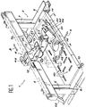
- Figure 1 shows a schematic perspective view of a machine according to the invention.
- Figure 2 shows a schematic cross-sectional view of a machine according to the invention.
- FIG. 3 represents an enlarged schematic view in the direction of the arrow III in FIG. 2.
- Figure 4 shows an enlarged schematic view with partial section of a machine receiving table according to the invention.
- a machine according to the invention designated as a whole by 1 comprises a frame 2 simultaneously supporting a movable table 3 for receiving the parts P to be machined and a machining carriage 4 movable for example under the action of a motorization 4a meshing with a rack or a drive nut.
- the chassis 2 is formed by assembling a main beam 5, consisting for example of a profile rectangular hollow, supported parallel to the ground, by two pillars 6 and 7 possibly reinforced by legs 6a, 7a and directly fixed on the base of the chassis materialized by two longitudinal members 8 and 9.
- a main beam 5 consisting for example of a profile rectangular hollow, supported parallel to the ground, by two pillars 6 and 7 possibly reinforced by legs 6a, 7a and directly fixed on the base of the chassis materialized by two longitudinal members 8 and 9.
- the longitudinal members 8 and 9 carry two parallel axes 10 and 11, on which the table 3 is displaceable in translation in the direction of the arrow A by means of rollers and lockable in the fixed position by means known per se.
- the movement of the table is manual or controlled by a control means such as a flywheel or a motor, not shown.
- the main beam 5 carries an axis 12 for guiding the carriage 4 equipped for this purpose with split ball bushings not shown and carries a square bar under its lower sole cooperating with support and leveling rollers of the carriage 4 in the translational movement of the carriage 4 in the direction of arrow B.
- the machines of the prior art could not under acceptable economic conditions integrate into the same chassis 2 a rectangular movement of large dimensions: thanks to a simple solution consisting in assigning the first translation A to the table 3 for receiving the parts and in assigning the second translation B to the carriage 4, the invention provides a machine in one piece, immediately usable and movable on its base 8-9 , which does not require any civil engineering work for its installation unlike the much larger machines of the prior art.
- the carriage 4 movable in translation B and immobilizable along the beam 5 by means of brakes manuals not shown, includes a rigid assembly 13 forming a receiving fork for an articulated arm capable of pivoting 180 ° around a vertical articulation axis 14 from the central position shown in solid lines to two parallel right-angle positions to beam 5, only one of which has been shown in broken lines.
- a half-disc 15 is provided for this purpose, serving both as an angular sector of orientation and as a means of fixing in position by means of brakes, not shown.
- the arm 20 articulated around the vertical axis 14 has a rectangular section with reinforcement brackets supporting a vertical displacement table 21.
- the vertical displacement table 21 comprises on the one hand a manual flywheel 22 for controlling (or a geared motor) a screw 23 with a trapezoidal thread and on the other hand a carriage 24 movable in translation in the direction of the arrow C along two sliding axes 25 ( Figure 1) and vertical guide of the carriage: for this purpose, the carriage comprises a displaceable nut 24a or a thread corresponding to the trapezoidal thread screw 23 so as to vertically move the carriage 24 by rotation of the steering wheel 22.
- the carriage 24 carries a device similar to the device which is the subject of European patent EP 0 196 941 which is considered to be an integral part of the present description.
- the device 26 thus comprises a housing 27 articulated around a horizontal axis 28 between a vertical position shown in broken lines and a horizontal position not shown, blocking means 29 being provided for immobilizing the housing 27 in a position chosen intermediary such as that shown in solid lines: the operation of the device 26 is thus analogous to that of an adjustable opening compass.
- all the extreme positions corresponding to directions parallel or perpendicular to selected reference directions are obtained with precision by virtue of a stop bearing on dry stops.
- the housing 27 is itself mounted on an orientation plate 30, so as to be able to pivot about an axis 31 perpendicular to the orientation plate 30 by 45 ° on either side of its middle position and to be held by locking means in position 31a.
- the housing 27 constitutes a machining unit comprising an electric motor 32 for driving and two pneumatic cylinders 33, 34 ensuring a pressing pressure for the polishing operations or making it possible to work in depth of cut thanks to a mechanical stop of spindle stroke stopped.
- the electric drive motor 32 is preferably an electric motor with frequency variation with an electric power of less than 5 kW, for driving the spindle 35 at a speed of rotation chosen as a function of the corresponding tool 36.
- an additional high speed motor (18,000 rpm) is advantageously provided.
- the spindle 35 is equipped with a system for reading and monitoring a template, not shown, to facilitate the reproduction of profiles of complex shape.
- the machine according to the invention provided with three degrees of freedom in translation A, B, C, and three degrees of freedom in rotation around the axes 14, 28 and 31 can thus easily follow profiles of complex shape, coordination displacements occurring naturally through simple geometric decomposition parts to be obtained: this machine, by its design, therefore makes it possible to receive appropriate digital commands of the axes of translation and rotation in the context of mass production or of computer-aided design and manufacture.
- the stones P or workpieces were stationary and did not move: they were placed or fixed to a fixed support, which avoided the transmission of vibration and resonances between the chassis of the machine and the support parts, because these vibrations were notably absorbed by the workshop floor.
- the low frequency vibrations close to the natural frequency of the chassis 2 are directly transmitted through the metal of the frame, which presents a significant risk of cracking for fragile materials such as marble or stones analogues.
- a system for fixing stones P to be machined comprises a plurality (FIG. 1) of slots 40 formed in the reception table 3.
- the lights 40 pass entirely through the table 3, including the upper plate 41 made of rubber or elastomer with non-slip reliefs not shown. This upper rubber plate is cut so as to reserve a metal border around each light 40.
- each socket 43 has the shape of a pierced coil, consisting of a central cylindrical barrel 44 and two end rings 45 having dimensions ensuring retention after engagement of the socket 43 in the slot 40: for this purpose, the diameter of the barrel 44 is less than the width 1 of the slot 40 and the diameter of a ring 45 is greater than the width 1 of the light and less than the diameter of the orifice 40a.
- the diameter of a ring 45 and the cutout of the rubber plate 41 are determined so that the ring 45 is only in contact with the aforementioned metal edge so as to obtain metal-to-metal contact during tightening.
- a valet 46 of known type is slidably mounted by its cylindrical foot 47 inside the cylindrical barrel 44 and preferably, mounted captive in a corresponding socket 43 while being retained by a pin 48.
- the valet 46 mounted in the socket 43 slides in the groove 40 to a chosen position for blocking a stone P.
- the simple application of a force on the valet 46 ensures the simultaneous locking of the valet 46 in the socket 43 and of the socket 43 in the groove 40, which makes it possible to obtain the desired clamping of the stone P.
- the machine according to the invention makes it possible to mill, drill, surface, mold and polish fragile stony materials such as marble or the like, without risk of cracking.
- the invention is not limited to the embodiment described, but on the contrary covers any modification of shape and any variant embodiment of a machine with three degrees of freedom in translation and three degrees of freedom in rotation, in which the table receiving stones is secured to the machine frame, and movable in translation inside the outline thereof.
Landscapes
- Engineering & Computer Science (AREA)
- Mechanical Engineering (AREA)
- Chemical & Material Sciences (AREA)
- Ceramic Engineering (AREA)
- Inorganic Chemistry (AREA)
- Mining & Mineral Resources (AREA)
- Machine Tool Units (AREA)
- Polishing Bodies And Polishing Tools (AREA)
Applications Claiming Priority (2)
| Application Number | Priority Date | Filing Date | Title |
|---|---|---|---|
| FR9301340 | 1993-02-08 | ||
| FR9301340A FR2701228B1 (fr) | 1993-02-08 | 1993-02-08 | Machine à fraiser, percer, surfacer, moulurer et polir des pierres ou matériau similaire. |
Publications (3)
| Publication Number | Publication Date |
|---|---|
| EP0611191A2 true EP0611191A2 (de) | 1994-08-17 |
| EP0611191A3 EP0611191A3 (de) | 1995-01-25 |
| EP0611191B1 EP0611191B1 (de) | 1999-09-08 |
Family
ID=9443820
Family Applications (1)
| Application Number | Title | Priority Date | Filing Date |
|---|---|---|---|
| EP19940400234 Expired - Lifetime EP0611191B1 (de) | 1993-02-08 | 1994-02-04 | Maschine zum Fräsen, Bohren, Oberflächenbearbeiten, Profilschneiden und Polieren von Gestein oder gleichartigem Material |
Country Status (4)
| Country | Link |
|---|---|
| EP (1) | EP0611191B1 (de) |
| DE (1) | DE69420436T2 (de) |
| ES (1) | ES2138652T3 (de) |
| FR (1) | FR2701228B1 (de) |
Cited By (13)
| Publication number | Priority date | Publication date | Assignee | Title |
|---|---|---|---|---|
| WO1997026111A1 (en) * | 1996-01-15 | 1997-07-24 | Mauro Di Mattia | Portable machine with positioning device for the working of hard materials |
| WO1999034954A1 (en) * | 1998-01-05 | 1999-07-15 | Lorenzo Saccon | Stone tile finishing system |
| EP1319487A3 (de) * | 2001-12-12 | 2004-03-24 | EM-DS Solutions Lizenzverwertung OHG | Elektrische Schneidvorrichtung, insbesondere für Kurvenschnitte im Trocken- oder Nass-Schnittverfahren für Fliesen, Naturstein, Kunststein, Betonplatten u.dgl |
| EP1422023A1 (de) * | 2002-09-20 | 2004-05-26 | Comandulli Costruzioni Meccaniche S.R.L. | Vorrichtung zum bearbeiten der Kanten von Platten aus Marmor und ähnlichen Materialien |
| CN104002231A (zh) * | 2014-06-18 | 2014-08-27 | 青岛建诚伟业机械制造有限公司 | 横梁组件及安装有该组件的砂光机 |
| CN105538077A (zh) * | 2015-12-15 | 2016-05-04 | 嵊州市古艺木雕装饰有限公司 | 一种用于装饰木板的打磨装置 |
| CN108406934A (zh) * | 2018-03-20 | 2018-08-17 | 郭林惠 | 一种塑料加工设备 |
| CN108422479A (zh) * | 2018-03-20 | 2018-08-21 | 郭林惠 | 一种新型塑料加工设备 |
| CN109049350A (zh) * | 2018-08-23 | 2018-12-21 | 云浮市谢之机械有限公司 | 大理石板材多功能加工机 |
| CN109940363A (zh) * | 2019-05-16 | 2019-06-28 | 烟台工程职业技术学院(烟台市技师学院) | 一种人工智能玩具组装机械手 |
| CN113103135A (zh) * | 2021-04-19 | 2021-07-13 | 兰州工业学院 | 一种行走式板材抛光装置 |
| CN113319354A (zh) * | 2021-08-03 | 2021-08-31 | 常州赫尚赫机械有限公司 | 一种用于加工销轴的高精度设备 |
| CN118144112A (zh) * | 2024-04-25 | 2024-06-07 | 四川省建筑设计研究院有限公司 | 一种玄武岩复合纤维景观板制备装置及制备方法 |
Families Citing this family (8)
| Publication number | Priority date | Publication date | Assignee | Title |
|---|---|---|---|---|
| WO2013093132A1 (es) * | 2011-12-23 | 2013-06-27 | Angel Abalos Cortazar | Máquina pulidora-lijadora de chaflanes. |
| CN111015450B (zh) * | 2019-12-31 | 2020-12-04 | 安徽省聚科石墨烯科技股份公司 | 一种石墨烯集成电路板打磨钻孔装置 |
| CN111168404B (zh) * | 2020-03-14 | 2022-08-30 | 山东理工职业学院 | 一种机械加工钻孔装置 |
| CN111843510A (zh) * | 2020-08-08 | 2020-10-30 | 杭州富阳正茂进出口有限公司 | 一种数控机械加工用车削打磨一体装置及其加工方法技术领域 |
| CN111890062A (zh) * | 2020-08-08 | 2020-11-06 | 杭州富阳正茂进出口有限公司 | 一种数控机械加工用车削打磨一体装置的加工方法 |
| CN112223000A (zh) * | 2020-09-25 | 2021-01-15 | 陈佳雯 | 一种陶瓷加工用磨边切割机 |
| CN112643432A (zh) * | 2020-12-18 | 2021-04-13 | 泉州市博凯工业设计有限公司 | 一种石材打磨用支撑装置及使用方法 |
| CN113681241B (zh) * | 2021-08-27 | 2022-09-02 | 无锡瑞圣机械科技有限公司 | 一种低地板轴桥制造用装置及其制造工艺 |
Family Cites Families (9)
| Publication number | Priority date | Publication date | Assignee | Title |
|---|---|---|---|---|
| BE506447A (de) * | 1950-10-18 | |||
| US2877815A (en) * | 1955-05-23 | 1959-03-17 | Hold Corp | Canting holddown clamp |
| US3923086A (en) * | 1974-02-25 | 1975-12-02 | Jr Daniel M Spohn | Adjustable radial arm apparatus for use with a router or the like |
| DE3532903A1 (de) * | 1985-09-14 | 1987-03-26 | Waldrich Werkzeugmasch | Portalschleifmaschine mit schleifscheiben-wechselvorrichtung |
| US4995288A (en) * | 1988-10-03 | 1991-02-26 | Dellapolla Michael | Saw guide |
| DE3839150C1 (de) * | 1988-11-17 | 1990-01-18 | Plickert, Reiner | |
| FR2652026B1 (fr) * | 1989-09-21 | 1993-07-23 | Gritti Olivier | Dispositif de serrage de pieces. |
| DE3934914A1 (de) * | 1989-10-20 | 1991-04-25 | Erbsloeh Julius & August | Portalwerkzeugmaschine, insbesondere zum polieren von werkstuecken |
| US5156383A (en) * | 1991-07-19 | 1992-10-20 | Williams Ronnie G | Window polishing stand |
-
1993
- 1993-02-08 FR FR9301340A patent/FR2701228B1/fr not_active Expired - Fee Related
-
1994
- 1994-02-04 EP EP19940400234 patent/EP0611191B1/de not_active Expired - Lifetime
- 1994-02-04 DE DE1994620436 patent/DE69420436T2/de not_active Expired - Fee Related
- 1994-02-04 ES ES94400234T patent/ES2138652T3/es not_active Expired - Lifetime
Cited By (14)
| Publication number | Priority date | Publication date | Assignee | Title |
|---|---|---|---|---|
| WO1997026111A1 (en) * | 1996-01-15 | 1997-07-24 | Mauro Di Mattia | Portable machine with positioning device for the working of hard materials |
| WO1999034954A1 (en) * | 1998-01-05 | 1999-07-15 | Lorenzo Saccon | Stone tile finishing system |
| EP1319487A3 (de) * | 2001-12-12 | 2004-03-24 | EM-DS Solutions Lizenzverwertung OHG | Elektrische Schneidvorrichtung, insbesondere für Kurvenschnitte im Trocken- oder Nass-Schnittverfahren für Fliesen, Naturstein, Kunststein, Betonplatten u.dgl |
| EP1422023A1 (de) * | 2002-09-20 | 2004-05-26 | Comandulli Costruzioni Meccaniche S.R.L. | Vorrichtung zum bearbeiten der Kanten von Platten aus Marmor und ähnlichen Materialien |
| CN104002231A (zh) * | 2014-06-18 | 2014-08-27 | 青岛建诚伟业机械制造有限公司 | 横梁组件及安装有该组件的砂光机 |
| CN105538077A (zh) * | 2015-12-15 | 2016-05-04 | 嵊州市古艺木雕装饰有限公司 | 一种用于装饰木板的打磨装置 |
| CN108406934A (zh) * | 2018-03-20 | 2018-08-17 | 郭林惠 | 一种塑料加工设备 |
| CN108422479A (zh) * | 2018-03-20 | 2018-08-21 | 郭林惠 | 一种新型塑料加工设备 |
| CN108406934B (zh) * | 2018-03-20 | 2018-12-28 | 惠州市索菱精密塑胶有限公司 | 一种塑料加工设备 |
| CN109049350A (zh) * | 2018-08-23 | 2018-12-21 | 云浮市谢之机械有限公司 | 大理石板材多功能加工机 |
| CN109940363A (zh) * | 2019-05-16 | 2019-06-28 | 烟台工程职业技术学院(烟台市技师学院) | 一种人工智能玩具组装机械手 |
| CN113103135A (zh) * | 2021-04-19 | 2021-07-13 | 兰州工业学院 | 一种行走式板材抛光装置 |
| CN113319354A (zh) * | 2021-08-03 | 2021-08-31 | 常州赫尚赫机械有限公司 | 一种用于加工销轴的高精度设备 |
| CN118144112A (zh) * | 2024-04-25 | 2024-06-07 | 四川省建筑设计研究院有限公司 | 一种玄武岩复合纤维景观板制备装置及制备方法 |
Also Published As
| Publication number | Publication date |
|---|---|
| FR2701228A1 (fr) | 1994-08-12 |
| ES2138652T3 (es) | 2000-01-16 |
| EP0611191B1 (de) | 1999-09-08 |
| DE69420436D1 (de) | 1999-10-14 |
| EP0611191A3 (de) | 1995-01-25 |
| FR2701228B1 (fr) | 1995-04-07 |
| DE69420436T2 (de) | 2000-02-17 |
Similar Documents
| Publication | Publication Date | Title |
|---|---|---|
| EP0611191B1 (de) | Maschine zum Fräsen, Bohren, Oberflächenbearbeiten, Profilschneiden und Polieren von Gestein oder gleichartigem Material | |
| FR3054466A3 (fr) | Centre d’usinage pour profiles metalliques | |
| FR1410534A (fr) | Dispositif pour l'usinage de pièces, par exemple dispositif de perçage | |
| EP0194173A2 (de) | Werkzeugmaschine mit einem senkrechten Spindel zum Fräsen und Bohren | |
| US4821457A (en) | Vertical oscillating spindle sanders | |
| AU662643B2 (en) | Improvements in portable machines for performing cuts in stone, marble, granite and the like | |
| FR2641722A1 (fr) | Dispositif pour l'entrainement d'une broche porte-outil | |
| FR2694720A1 (fr) | Dispositif et procédé automatique de fraisage et de polissage. | |
| EP0354136A1 (de) | Mehrwertige Struktur für alle Bearbeitungsvorgänge, hauptsächlich für empfindliches Material | |
| EP1522378B1 (de) | Fünfachsige Werkzeugmaschine mit fortlaufender Schleifscheibenabrichtvorrichtung | |
| FR2471844A1 (fr) | Table roulante pour machines a travailler le bois | |
| EP0023876A1 (de) | Werkzeugschleifmaschinen | |
| EP0252802B1 (de) | Holzbearbeitungsmaschine zur Fertigung von Fensterrahmen | |
| FR2506652A3 (fr) | Perfectionnements aux machines-outils du genre des rectifieuses planes | |
| EP0260199A1 (de) | Universalmaschine zur Bearbeitung von Holz oder ähnlichem Werkstoff | |
| FR2630035A1 (fr) | Machine pour debiter, polir ou fraiser des elements a faces spheriques en pierre | |
| FR2575101A1 (fr) | Outil pour l'usinage de surfaces optiques et machine utilisant un tel outil | |
| FR2507514A1 (fr) | Machine pour l'usinage de finition des flancs de dents de pieces dentees | |
| FR2634411A1 (fr) | Structure polyvalente pour tous travaux d'usinage principalement de materiaux tendres | |
| FR2614570A1 (fr) | Machine perfectionnee pour l'affutage des fers tranchants d'outils de coupe notamment pour la menuiserie | |
| FR2725394A1 (fr) | Machine-outil pour usiner des pieces selon un profil determine | |
| FR2571291A1 (fr) | Machine de fraisage et polissage d'un chant d'une piece en materiau dur | |
| FR2703286A1 (fr) | Procédé d'usinage des chants de dalles de pierre et appareil le mettant en Óoeuvre. | |
| FR2533491A1 (fr) | Machine universelle pour le traitement du bois | |
| CH638423A5 (fr) | Dispositif de rhabillage pour le profilage de roues de meulage. |
Legal Events
| Date | Code | Title | Description |
|---|---|---|---|
| PUAI | Public reference made under article 153(3) epc to a published international application that has entered the european phase |
Free format text: ORIGINAL CODE: 0009012 |
|
| AK | Designated contracting states |
Kind code of ref document: A2 Designated state(s): BE CH DE ES IT LI |
|
| PUAL | Search report despatched |
Free format text: ORIGINAL CODE: 0009013 |
|
| AK | Designated contracting states |
Kind code of ref document: A3 Designated state(s): BE CH DE ES IT LI |
|
| 17P | Request for examination filed |
Effective date: 19950623 |
|
| 17Q | First examination report despatched |
Effective date: 19980119 |
|
| GRAG | Despatch of communication of intention to grant |
Free format text: ORIGINAL CODE: EPIDOS AGRA |
|
| GRAG | Despatch of communication of intention to grant |
Free format text: ORIGINAL CODE: EPIDOS AGRA |
|
| GRAH | Despatch of communication of intention to grant a patent |
Free format text: ORIGINAL CODE: EPIDOS IGRA |
|
| GRAH | Despatch of communication of intention to grant a patent |
Free format text: ORIGINAL CODE: EPIDOS IGRA |
|
| GRAA | (expected) grant |
Free format text: ORIGINAL CODE: 0009210 |
|
| AK | Designated contracting states |
Kind code of ref document: B1 Designated state(s): BE CH DE ES IT LI |
|
| REG | Reference to a national code |
Ref country code: CH Ref legal event code: EP |
|
| REF | Corresponds to: |
Ref document number: 69420436 Country of ref document: DE Date of ref document: 19991014 |
|
| REG | Reference to a national code |
Ref country code: CH Ref legal event code: NV Representative=s name: PATENTANWALTSBUERO JEAN HUNZIKER |
|
| ITF | It: translation for a ep patent filed | ||
| REG | Reference to a national code |
Ref country code: ES Ref legal event code: FG2A Ref document number: 2138652 Country of ref document: ES Kind code of ref document: T3 |
|
| PG25 | Lapsed in a contracting state [announced via postgrant information from national office to epo] |
Ref country code: ES Free format text: LAPSE BECAUSE OF NON-PAYMENT OF DUE FEES Effective date: 20000205 |
|
| PG25 | Lapsed in a contracting state [announced via postgrant information from national office to epo] |
Ref country code: LI Free format text: LAPSE BECAUSE OF NON-PAYMENT OF DUE FEES Effective date: 20000229 Ref country code: CH Free format text: LAPSE BECAUSE OF NON-PAYMENT OF DUE FEES Effective date: 20000229 |
|
| PLBE | No opposition filed within time limit |
Free format text: ORIGINAL CODE: 0009261 |
|
| STAA | Information on the status of an ep patent application or granted ep patent |
Free format text: STATUS: NO OPPOSITION FILED WITHIN TIME LIMIT |
|
| 26N | No opposition filed | ||
| REG | Reference to a national code |
Ref country code: CH Ref legal event code: PL |
|
| REG | Reference to a national code |
Ref country code: ES Ref legal event code: FD2A Effective date: 20010910 |
|
| PGFP | Annual fee paid to national office [announced via postgrant information from national office to epo] |
Ref country code: DE Payment date: 20030303 Year of fee payment: 10 |
|
| PGFP | Annual fee paid to national office [announced via postgrant information from national office to epo] |
Ref country code: BE Payment date: 20030312 Year of fee payment: 10 |
|
| PG25 | Lapsed in a contracting state [announced via postgrant information from national office to epo] |
Ref country code: BE Free format text: LAPSE BECAUSE OF NON-PAYMENT OF DUE FEES Effective date: 20040228 |
|
| BERE | Be: lapsed |
Owner name: S.A. *THIBAUT Effective date: 20040228 |
|
| PG25 | Lapsed in a contracting state [announced via postgrant information from national office to epo] |
Ref country code: DE Free format text: LAPSE BECAUSE OF NON-PAYMENT OF DUE FEES Effective date: 20040901 |
|
| PG25 | Lapsed in a contracting state [announced via postgrant information from national office to epo] |
Ref country code: IT Free format text: LAPSE BECAUSE OF NON-PAYMENT OF DUE FEES;WARNING: LAPSES OF ITALIAN PATENTS WITH EFFECTIVE DATE BEFORE 2007 MAY HAVE OCCURRED AT ANY TIME BEFORE 2007. THE CORRECT EFFECTIVE DATE MAY BE DIFFERENT FROM THE ONE RECORDED. Effective date: 20050204 |