EP0611200A1 - Dichte Verschlussvorrichtung und Verbindung an einem Gehäuse von einem Aussenrohr - Google Patents
Dichte Verschlussvorrichtung und Verbindung an einem Gehäuse von einem Aussenrohr Download PDFInfo
- Publication number
- EP0611200A1 EP0611200A1 EP94400258A EP94400258A EP0611200A1 EP 0611200 A1 EP0611200 A1 EP 0611200A1 EP 94400258 A EP94400258 A EP 94400258A EP 94400258 A EP94400258 A EP 94400258A EP 0611200 A1 EP0611200 A1 EP 0611200A1
- Authority
- EP
- European Patent Office
- Prior art keywords
- sleeve
- shutter
- enclosure
- head
- pipe
- Prior art date
- Legal status (The legal status is an assumption and is not a legal conclusion. Google has not performed a legal analysis and makes no representation as to the accuracy of the status listed.)
- Granted
Links
Images


Classifications
-
- F—MECHANICAL ENGINEERING; LIGHTING; HEATING; WEAPONS; BLASTING
- F16—ENGINEERING ELEMENTS AND UNITS; GENERAL MEASURES FOR PRODUCING AND MAINTAINING EFFECTIVE FUNCTIONING OF MACHINES OR INSTALLATIONS; THERMAL INSULATION IN GENERAL
- F16L—PIPES; JOINTS OR FITTINGS FOR PIPES; SUPPORTS FOR PIPES, CABLES OR PROTECTIVE TUBING; MEANS FOR THERMAL INSULATION IN GENERAL
- F16L41/00—Branching pipes; Joining pipes to walls
- F16L41/08—Joining pipes to walls or pipes, the joined pipe axis being perpendicular to the plane of a wall or to the axis of another pipe
- F16L41/16—Joining pipes to walls or pipes, the joined pipe axis being perpendicular to the plane of a wall or to the axis of another pipe the branch pipe comprising fluid cut-off means
-
- Y—GENERAL TAGGING OF NEW TECHNOLOGICAL DEVELOPMENTS; GENERAL TAGGING OF CROSS-SECTIONAL TECHNOLOGIES SPANNING OVER SEVERAL SECTIONS OF THE IPC; TECHNICAL SUBJECTS COVERED BY FORMER USPC CROSS-REFERENCE ART COLLECTIONS [XRACs] AND DIGESTS
- Y10—TECHNICAL SUBJECTS COVERED BY FORMER USPC
- Y10T—TECHNICAL SUBJECTS COVERED BY FORMER US CLASSIFICATION
- Y10T137/00—Fluid handling
- Y10T137/598—With repair, tapping, assembly, or disassembly means
- Y10T137/612—Tapping a pipe, keg, or apertured tank under pressure
- Y10T137/613—With valved closure or bung
- Y10T137/6133—Combined rotary and longitudinal movement of valve
Definitions
- the invention relates to a device for sealing and connecting an enclosure to an external pipe.
- the invention aims to provide a reliable and inexpensive device which is simple in design and easy to use in order to ensure the sealed closure of an enclosure and the selective connection of the latter to an external pipe.
- the subject of the invention is such a device comprising a valve body mounted in leaktight manner through a wall of said enclosure, a shutter received in said body and means for selectively sealingly connecting said enclosure to said pipe.
- said connection means comprise a removable sleeve adapted to be fixed externally in a sealed manner to said body and an actuating member of said shutter rotatably mounted in said sleeve to move said shutter in said sleeve between a closed position and said open position in which said enclosure communicates with said pipe via said body and said sleeve.
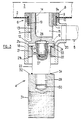
- the device shown comprises a valve 1 mounted in leaktight manner in a wall 2 of an enclosure 3, and a device 4 for connecting the enclosure 3 to an external pipe 5.
- the valve 1 comprises a body 6 and a shutter 7.
- the body 6 comprises a ring 8 of cylindrical tubular shape internally and externally threaded and intended to be mounted through a hole in the wall 2 having substantially the same diameter as the outside diameter of the ring 8.
- the ring 8 has at one of its ends an annular flange 9 intended to come to bear against the inner face of the wall 2 at the periphery of the aforementioned hole, while an annular nut 10 of substantially outside diameter equal to that of the collar 9 can be screwed externally to the ring 8.
- the tightening of the wall 2 between the collar 9 and the annular nut 10 with, if necessary, interposition of a seal 9a allows sealing between the wall 2 and the body 6.
- the length of the threaded part of the ring 8 is substantially greater than the cumulative thicknesses of the wall 2 and of the annular nut 10 so that, in the mounted position of the body 6 on the wall 2, part of the threaded end of the ring 8 projects outwards beyond the annular nut 10.
- the end 11 of the ring 8 which is opposite the flange 9 forms a seat against which the shutter 7 can come to bear in the closed position of the valve 1.
- This shutter 7 comprises a head 12 carrying a cylindrical part 13 threaded externally so as to be able to be screwed into the ring 8.
- the cylindrical part 13 of the shutter 7 has, from its end opposite the head 12, an axial bore 14 communicating with a transverse orifice 15 formed, in the vicinity of the head 12, through the wall of the cylindrical part 13.
- the latter has a length such that its external thread remains partially engaged in the internal thread of the ring 8 when the shutter is brought into an open position where the orifice 15 is entirely clear beyond the seat 11.
- the head 12 has the shape of a disc whose outside diameter is slightly greater than that of the tubular part 13 considered at the top of the thread, while being at most equal to the outside diameter of the ring 8 considered at the bottom of the thread.
- the head 12 thus defines, on the side of the tubular part 13, an annular shoulder 16 intended to be tightened against the annular seat 11 of the ring 8 to ensure the tight closure of the valve 1 when the shutter 7 is fully screwed in. the body 6.
- the head 12 has in its outer face a groove or imprint 17 intended to allow the screwing and unscrewing of the shutter 7 by means of a screwdriver or of said connection device 4 as will be described below.
- the groove 17 has, for example, the shape of a cavity with rectilinear lateral edges and with a hemispherical or cylindrical bottom.
- the connection device 4 comprises a cylindrical tubular sleeve 18 threaded at one of its ends at 19 so as to be able to be screwed onto the outer part of the ring 8 which projects beyond the annular nut 10.
- the sleeve 18 comprises, in the vicinity of its threaded end 19, a transverse tubular end piece 20 making it possible to connect in a manner tightens its internal volume to the external pipe 5.
- the sleeve 18 internally comprises a cylindrical annular part 21, the smooth internal cylindrical wall 22 of which constitutes a bearing surface in which a piston or slide 23 can slide and turn, while the opposite planar faces 21a and 21b of this part 21 constitute stops for limiting the stroke of the slide 23.
- the slider 23 has the shape of a cylindrical solid part whose external diameter is adapted to allow its sliding and its rotation with friction in the annular part 21.
- the slider 23 ends at one end by a bearing 24 of larger diameter defining a shoulder 25 capable of coming to bear against the face 21a in order to limit the stroke of the slide 23 inside the sleeve 18.
- the slide 23 is pierced axially with a tapped blind hole 26 intended to receive a threaded cylindrical part 27 having at one of its ends a projection 28 of shape and dimensions complementary to those of the groove 17.
- the slide 23 ends in a threaded axial extension 29 of smaller diameter and intended to be received in a tapped blind hole 30 drilled axially in one end of a cylindrical handle 31 having on at least part of its cylindrical outer wall of the grooves, indentations or similar means intended to prevent the sliding of the hand of the user when he actuates the handle 31 for tightening or loosening the shutter 7 as will be described below.
- This handle 31 has an outside diameter at most equal to the inside diameter of the sleeve and greater than the inside diameter of the annular piece 21 so that its end face in which the hole 30 is drilled defines a shoulder 32 capable of coming to bear against the face 21b of the annular piece 21 to limit the stroke of the slide 23 in the direction which tends to make it come out sleeve 18.
- connection device 4 is completed by two O-rings 33 and 34 (not shown in FIG. 1) mounted on the slide 23 on either side of the annular part 21.
- the sleeve 18 is made of chloride polyvinyl, while all the other parts of the valve and the connection device are in "DELRIN” or other polyacetal.
- connection device 4 To assemble the connection device 4, the threaded piece 27 is screwed fully into the hole 26 until the projection 28 is applied against the end of the slide 23.
- This embodiment of the projection 28, which is a part subject to wear, allows easy periodic replacement.
- the O-ring 33 is then placed on the slide 23 and it is introduced into the sleeve 18 from its end 19. During this movement, the O-ring 33 is pushed back by the face 21a until it comes into abutment against the shoulder 25. The end of the slide 23 adjacent to its threaded portion 29 then protrudes from the sleeve on the side opposite to the end piece 20 and the O-ring 34 can be placed thereon then screwed the handle 31 on the threaded end 29. By fully pushing the handle 31 towards the inside of the sleeve, the O-ring 34 is pushed back by the face 21b against the shoulder 32 and the two seals 33 and 34 are then in place.
- the shutter 7 can be operated, either by means of a conventional tool of the screwdriver type, or by means of the connection device 4. In the latter case, the threaded end 19 of the sleeve 18 is screwed on the projecting part of the ring 8 until the tightening exerted provides the desired seal.
- the slide 23 is turned by means of the handle 31 until the projection 28 engages in the groove 17. If this has not been not yet done, the end piece 20 is then connected to the external pipe 5 by any suitable means intended to ensure a sealed connection.
- the shutter 7 is unscrewed by rotating the handle 31 in the desired direction as would be done with an ordinary screwdriver.
- the orifice 15 is placed in communication with the interior volume of the sleeve and the pipe 5 and the movement is continued until the shoulder 25 comes to bear against the face 21a with interposition of the seal. sealing 33.
- the length of the shutter 7 is such that, in this open position, it remains screwed into the ring 8. Consequently, the loosening torque exerted on the handle 31 by the user has the effect of compressing the seal 33 between the shoulder 25 and the face 21a and thus ensure the seal between the slide 23 and the annular part 21.
- This stop position is chosen so that the orifice 15 is then aligned with the end piece 20. The enclosure 3 is thus tightly connected to the pipe 5.
- the handle 31 is turned in the direction which tends to ensure the screwing of the shutter 7 in the ring 8 until the shoulder 32 comes to compress the seal 34 against the face 21b as shown in Figure 2.
- the axial position of abutment of the shoulder 32 against the face 21b is chosen to limit the tightening torque of the shutter 7 in the body 6 to the desired value to ensure the proper seal in position valve closed 1.
- one or more lip seals or the like may be provided between the slide 23 and the annular part 21 and / or between the bearing surface 24 and the inner wall of the sleeve 18 in order to improve the seal. of the connection device during the time which separates the passage from the open position to the closed position of the shutter, and vice versa. In order to limit leaks during this transition between opening and closing, it is preferable that the shutter stroke is obtained over a small number of rotations of the slide and therefore give a significant pitch to the thread of the shutter 7.
- the device of the invention is advantageously used with a flexible enclosure or cover having excellent barrier properties with respect to humidity and the inert gas possibly used to fill the enclosure, as well as excellent solidity both in terms of tear resistance than impact resistance, so as not to have to resort to other additional elements for the packaging of parts or machines.
- the different components can have the following approximate unit weights: or a total weight of approximately 431 g / m2.
- Such a composite material constitutes a total barrier against humidity and inert gases, including helium, while offering remarkable resistance to mechanical aggressions (shocks, tears).
- the laminate used in the composition of component a) is produced by coextrusion of three layers into a tube which is blown at a fairly low rate (1: 1 to 1.5: 1) and which is stretched longitudinally for l '' orient uniaxially.
- the blown tube is laid flat, cut in a helix and deployed to form a flat sheet whose direction of orientation makes an angle with the longitudinal direction of the sheet.
- Four sheets are then combined, with their crossed directions of orientation, into a film which is laminated and stretched (for example at 2.25: 1) bi-directionally at a relatively low temperature. Details regarding this type of laminate and its preparation can be found in GB-A-1,526,722, GB-A-1,526,723 and GB-A-1,526,724, the teachings of which are incorporated herein by reference.
Landscapes
- Engineering & Computer Science (AREA)
- General Engineering & Computer Science (AREA)
- Mechanical Engineering (AREA)
- Valve Housings (AREA)
- Quick-Acting Or Multi-Walled Pipe Joints (AREA)
- Mechanically-Actuated Valves (AREA)
- Laying Of Electric Cables Or Lines Outside (AREA)
- Sliding Valves (AREA)
- Feeding And Controlling Fuel (AREA)
- Cable Accessories (AREA)
- Pipe Accessories (AREA)
Applications Claiming Priority (2)
| Application Number | Priority Date | Filing Date | Title |
|---|---|---|---|
| FR9301469 | 1993-02-10 | ||
| FR9301469A FR2701528B1 (fr) | 1993-02-10 | 1993-02-10 | Dispositif de fermeture étanche et de raccordement d'une enceinte à une canalisation extérieure et enceinte équipée d'un tel dispositif. |
Publications (2)
| Publication Number | Publication Date |
|---|---|
| EP0611200A1 true EP0611200A1 (de) | 1994-08-17 |
| EP0611200B1 EP0611200B1 (de) | 2001-05-09 |
Family
ID=9443912
Family Applications (1)
| Application Number | Title | Priority Date | Filing Date |
|---|---|---|---|
| EP94400258A Expired - Lifetime EP0611200B1 (de) | 1993-02-10 | 1994-02-08 | Dichte Verschluss- und Verbindungsvorrichtung von einem Aussenrohr an einem Gehäuse |
Country Status (6)
| Country | Link |
|---|---|
| US (1) | US5435341A (de) |
| EP (1) | EP0611200B1 (de) |
| AT (1) | ATE201095T1 (de) |
| CA (1) | CA2115335A1 (de) |
| DE (1) | DE69427170D1 (de) |
| FR (1) | FR2701528B1 (de) |
Families Citing this family (2)
| Publication number | Priority date | Publication date | Assignee | Title |
|---|---|---|---|---|
| GB2444503A (en) * | 2006-05-11 | 2008-06-11 | Stephen Whale | Tee fitting with interchangeable valve / access port |
| GB2496096A (en) * | 2011-09-27 | 2013-05-08 | Bosch Gmbh Robert | Test apparatus |
Citations (6)
| Publication number | Priority date | Publication date | Assignee | Title |
|---|---|---|---|---|
| GB194021A (en) * | 1921-12-15 | 1923-03-08 | Silas Rees | Improvements in or relating to means for use in connecting cocks, taps, and the like to pipe systems or containers |
| FR1160843A (fr) * | 1956-11-14 | 1958-08-11 | Dispositif perfectionné d'assemblage pour les prises de branchement sur les conduites de distribution de fluides | |
| FR2066414A5 (de) | 1969-10-18 | 1971-08-06 | Pass Cy Ltd | |
| GB1526724A (en) | 1975-08-27 | 1978-09-27 | Rasmussen O | Method of forming a laminate |
| GB1526723A (en) | 1975-08-27 | 1978-09-27 | Rasmussen O | Co-extruded sheet with properties resembling a cross-laminate and method of producing said sheet |
| GB2051991A (en) * | 1979-07-03 | 1981-01-21 | British Gas Corp | Method of and apparatus for making a connection to a pipe |
Family Cites Families (2)
| Publication number | Priority date | Publication date | Assignee | Title |
|---|---|---|---|---|
| DE2551124A1 (de) * | 1975-11-14 | 1977-05-26 | Bosch Gmbh Robert | Fuellvorrichtung fuer den gasraum eines druckbehaelters |
| US4071012A (en) * | 1976-04-23 | 1978-01-31 | The United States Of America As Represented By The Secretary Of The Navy | Fluid fill or bleed apparatus |
-
1993
- 1993-02-10 FR FR9301469A patent/FR2701528B1/fr not_active Expired - Fee Related
-
1994
- 1994-02-08 DE DE69427170T patent/DE69427170D1/de not_active Expired - Lifetime
- 1994-02-08 AT AT94400258T patent/ATE201095T1/de active
- 1994-02-08 EP EP94400258A patent/EP0611200B1/de not_active Expired - Lifetime
- 1994-02-09 US US08/193,595 patent/US5435341A/en not_active Expired - Fee Related
- 1994-02-09 CA CA002115335A patent/CA2115335A1/fr not_active Abandoned
Patent Citations (6)
| Publication number | Priority date | Publication date | Assignee | Title |
|---|---|---|---|---|
| GB194021A (en) * | 1921-12-15 | 1923-03-08 | Silas Rees | Improvements in or relating to means for use in connecting cocks, taps, and the like to pipe systems or containers |
| FR1160843A (fr) * | 1956-11-14 | 1958-08-11 | Dispositif perfectionné d'assemblage pour les prises de branchement sur les conduites de distribution de fluides | |
| FR2066414A5 (de) | 1969-10-18 | 1971-08-06 | Pass Cy Ltd | |
| GB1526724A (en) | 1975-08-27 | 1978-09-27 | Rasmussen O | Method of forming a laminate |
| GB1526723A (en) | 1975-08-27 | 1978-09-27 | Rasmussen O | Co-extruded sheet with properties resembling a cross-laminate and method of producing said sheet |
| GB2051991A (en) * | 1979-07-03 | 1981-01-21 | British Gas Corp | Method of and apparatus for making a connection to a pipe |
Also Published As
| Publication number | Publication date |
|---|---|
| US5435341A (en) | 1995-07-25 |
| ATE201095T1 (de) | 2001-05-15 |
| EP0611200B1 (de) | 2001-05-09 |
| CA2115335A1 (fr) | 1994-08-11 |
| DE69427170D1 (de) | 2001-06-13 |
| FR2701528B1 (fr) | 1995-03-24 |
| FR2701528A1 (fr) | 1994-08-19 |
Similar Documents
| Publication | Publication Date | Title |
|---|---|---|
| EP0549450B1 (de) | Handschuhhalteeinrichtung für Isolierraum | |
| EP0538094A1 (de) | Metallbehälter, der entlang einer Schwächungslinie teilweise geöffnet werden kann | |
| EP0440564B1 (de) | Vorrichtung zum Verbinden eines Schlauchendes mit dem Ende eines starren Rohres | |
| CA2434559A1 (fr) | Dispositif de robinet pour bouteille de gaz sous pression | |
| FR2514060A1 (fr) | Serrure a fermeture automatique par clenche pivotante | |
| EP0611200B1 (de) | Dichte Verschluss- und Verbindungsvorrichtung von einem Aussenrohr an einem Gehäuse | |
| CA2645088C (fr) | Antidevireur a ressort | |
| FR2475504A1 (fr) | Sac hermetiquement scelle et rempli de liquide et procede pour stocker et distribuer un liquide sensible a l'oxygene au moyen de ce sac | |
| FR2825350A1 (fr) | Joint multicouche, bouchon ou col de recipient comprenant un tel joint, et procedes de realisation | |
| FR2625179A1 (fr) | Conditionnement, tel que bouteille, bocal ou autre recipient et joint d'etancheite pour ledit conditionnement | |
| EP0473479A1 (de) | Fensterrahmenprofil | |
| FR2572925A1 (fr) | Dispositif pour le polissage des dents | |
| FR2756347A1 (fr) | Vanne a boisseau cylindrique | |
| WO2003011699A1 (fr) | Bouchon comprenant une jupe interieure d'etancheite | |
| FR2551173A1 (fr) | Valve pour recipient contenant un gaz sous pression, notamment un gaz de petrole liquefie, joint conique de pre-etancheite pour celle-ci et bouteille comprenant une telle valve | |
| FR2828172A1 (fr) | Bouchon comportant un joint solidarise a sa paroi transversale, au centre d'une jupe interieure | |
| EP0202156A1 (de) | Ringförmige Dichtungsanordnung, insbesondere für Klappen oder Ventile | |
| FR2788582A1 (fr) | Dispositif de branchement d'une canalisation de derivation sur une canalisation de transport de fluide | |
| EP0462139B1 (de) | Durchgangsventil mit schlauchmembran und hemisphärischem absperrkörper | |
| FR2905115A1 (fr) | Emballage, type sac, comprenant un dispositif de fermeture/ouverture, notamment destine a la conservation de produits agroalimentaires | |
| FR2872446A1 (fr) | Dispositif de transfert etanche a double porte comportant des organes d'actionnement des portes equipes de hublots | |
| WO2024110540A1 (fr) | Système de casse pression entre deux locaux | |
| FR3032743B1 (fr) | Dispositif d'obturation d'une baie comprenant une poignee rotative apte a engendrer une cinematique de desengagement en deux temps de l'ouvrant a partir du dormant | |
| CH276994A (fr) | Dispositif obturateur automatique d'un récipient présentant un goulot. | |
| FR2514331A1 (fr) | Emballage ou conteneur etanche, notamment pour le transport de munitions a haute altitude dans un aeronef non pressurise |
Legal Events
| Date | Code | Title | Description |
|---|---|---|---|
| PUAI | Public reference made under article 153(3) epc to a published international application that has entered the european phase |
Free format text: ORIGINAL CODE: 0009012 |
|
| AK | Designated contracting states |
Kind code of ref document: A1 Designated state(s): AT BE CH DE DK ES FR GB GR IE IT LI LU MC NL PT SE |
|
| 17P | Request for examination filed |
Effective date: 19950217 |
|
| 17Q | First examination report despatched |
Effective date: 19960329 |
|
| GRAG | Despatch of communication of intention to grant |
Free format text: ORIGINAL CODE: EPIDOS AGRA |
|
| RTI1 | Title (correction) |
Free format text: SEALED CLOSURE AND JOINT DEVICE OF AN ENCLOSURE TO AN EXTERNAL PIPE |
|
| GRAG | Despatch of communication of intention to grant |
Free format text: ORIGINAL CODE: EPIDOS AGRA |
|
| GRAH | Despatch of communication of intention to grant a patent |
Free format text: ORIGINAL CODE: EPIDOS IGRA |
|
| GRAH | Despatch of communication of intention to grant a patent |
Free format text: ORIGINAL CODE: EPIDOS IGRA |
|
| GRAA | (expected) grant |
Free format text: ORIGINAL CODE: 0009210 |
|
| AK | Designated contracting states |
Kind code of ref document: B1 Designated state(s): AT BE CH DE DK ES FR GB GR IE IT LI LU MC NL PT SE |
|
| PG25 | Lapsed in a contracting state [announced via postgrant information from national office to epo] |
Ref country code: NL Free format text: LAPSE BECAUSE OF FAILURE TO SUBMIT A TRANSLATION OF THE DESCRIPTION OR TO PAY THE FEE WITHIN THE PRESCRIBED TIME-LIMIT Effective date: 20010509 Ref country code: IT Free format text: LAPSE BECAUSE OF FAILURE TO SUBMIT A TRANSLATION OF THE DESCRIPTION OR TO PAY THE FEE WITHIN THE PRESCRIBED TIME-LIMIT;WARNING: LAPSES OF ITALIAN PATENTS WITH EFFECTIVE DATE BEFORE 2007 MAY HAVE OCCURRED AT ANY TIME BEFORE 2007. THE CORRECT EFFECTIVE DATE MAY BE DIFFERENT FROM THE ONE RECORDED. Effective date: 20010509 Ref country code: IE Free format text: LAPSE BECAUSE OF FAILURE TO SUBMIT A TRANSLATION OF THE DESCRIPTION OR TO PAY THE FEE WITHIN THE PRESCRIBED TIME-LIMIT Effective date: 20010509 Ref country code: AT Free format text: LAPSE BECAUSE OF FAILURE TO SUBMIT A TRANSLATION OF THE DESCRIPTION OR TO PAY THE FEE WITHIN THE PRESCRIBED TIME-LIMIT Effective date: 20010509 |
|
| REF | Corresponds to: |
Ref document number: 201095 Country of ref document: AT Date of ref document: 20010515 Kind code of ref document: T |
|
| REG | Reference to a national code |
Ref country code: CH Ref legal event code: EP |
|
| REF | Corresponds to: |
Ref document number: 69427170 Country of ref document: DE Date of ref document: 20010613 |
|
| REG | Reference to a national code |
Ref country code: IE Ref legal event code: FG4D Free format text: FRENCH |
|
| PG25 | Lapsed in a contracting state [announced via postgrant information from national office to epo] |
Ref country code: SE Free format text: LAPSE BECAUSE OF FAILURE TO SUBMIT A TRANSLATION OF THE DESCRIPTION OR TO PAY THE FEE WITHIN THE PRESCRIBED TIME-LIMIT Effective date: 20010809 Ref country code: PT Free format text: LAPSE BECAUSE OF FAILURE TO SUBMIT A TRANSLATION OF THE DESCRIPTION OR TO PAY THE FEE WITHIN THE PRESCRIBED TIME-LIMIT Effective date: 20010809 Ref country code: DK Free format text: LAPSE BECAUSE OF FAILURE TO SUBMIT A TRANSLATION OF THE DESCRIPTION OR TO PAY THE FEE WITHIN THE PRESCRIBED TIME-LIMIT Effective date: 20010809 |
|
| PG25 | Lapsed in a contracting state [announced via postgrant information from national office to epo] |
Ref country code: GR Free format text: LAPSE BECAUSE OF FAILURE TO SUBMIT A TRANSLATION OF THE DESCRIPTION OR TO PAY THE FEE WITHIN THE PRESCRIBED TIME-LIMIT Effective date: 20010810 Ref country code: DE Free format text: LAPSE BECAUSE OF FAILURE TO SUBMIT A TRANSLATION OF THE DESCRIPTION OR TO PAY THE FEE WITHIN THE PRESCRIBED TIME-LIMIT Effective date: 20010810 |
|
| NLV1 | Nl: lapsed or annulled due to failure to fulfill the requirements of art. 29p and 29m of the patents act | ||
| PG25 | Lapsed in a contracting state [announced via postgrant information from national office to epo] |
Ref country code: ES Free format text: LAPSE BECAUSE OF FAILURE TO SUBMIT A TRANSLATION OF THE DESCRIPTION OR TO PAY THE FEE WITHIN THE PRESCRIBED TIME-LIMIT Effective date: 20011130 |
|
| GBT | Gb: translation of ep patent filed (gb section 77(6)(a)/1977) |
Effective date: 20011127 |
|
| REG | Reference to a national code |
Ref country code: GB Ref legal event code: 9110 Free format text: EXTENSION ALLOWED SEALED CLOSURE AND JOINT DEVICE OF AN ENCLOSURE TO AN EXTERNAL PIPE PERIOD(S) PRESCRIBED BY RULE(S) SCHEDULE 4 PARA 2 EXTENDED UNDER RULE 110(6) IN ACCORDANCE WITH THE DECISION OF THE COMPTROLLER DATED 22 NOV 2001. |
|
| REG | Reference to a national code |
Ref country code: GB Ref legal event code: IF02 |
|
| PG25 | Lapsed in a contracting state [announced via postgrant information from national office to epo] |
Ref country code: LU Free format text: LAPSE BECAUSE OF NON-PAYMENT OF DUE FEES Effective date: 20020208 |
|
| REG | Reference to a national code |
Ref country code: IE Ref legal event code: FD4D |
|
| PG25 | Lapsed in a contracting state [announced via postgrant information from national office to epo] |
Ref country code: LI Free format text: LAPSE BECAUSE OF NON-PAYMENT OF DUE FEES Effective date: 20020228 Ref country code: CH Free format text: LAPSE BECAUSE OF NON-PAYMENT OF DUE FEES Effective date: 20020228 |
|
| PGFP | Annual fee paid to national office [announced via postgrant information from national office to epo] |
Ref country code: GB Payment date: 20020228 Year of fee payment: 9 |
|
| PLBE | No opposition filed within time limit |
Free format text: ORIGINAL CODE: 0009261 |
|
| STAA | Information on the status of an ep patent application or granted ep patent |
Free format text: STATUS: NO OPPOSITION FILED WITHIN TIME LIMIT |
|
| 26N | No opposition filed | ||
| PG25 | Lapsed in a contracting state [announced via postgrant information from national office to epo] |
Ref country code: MC Free format text: LAPSE BECAUSE OF NON-PAYMENT OF DUE FEES Effective date: 20020901 |
|
| REG | Reference to a national code |
Ref country code: CH Ref legal event code: PL |
|
| PG25 | Lapsed in a contracting state [announced via postgrant information from national office to epo] |
Ref country code: GB Free format text: LAPSE BECAUSE OF NON-PAYMENT OF DUE FEES Effective date: 20030208 |
|
| GBPC | Gb: european patent ceased through non-payment of renewal fee | ||
| REG | Reference to a national code |
Ref country code: GB Ref legal event code: 728V |
|
| REG | Reference to a national code |
Ref country code: FR Ref legal event code: ST |
|
| REG | Reference to a national code |
Ref country code: FR Ref legal event code: RN |
|
| PGFP | Annual fee paid to national office [announced via postgrant information from national office to epo] |
Ref country code: FR Payment date: 20040216 Year of fee payment: 11 |
|
| REG | Reference to a national code |
Ref country code: FR Ref legal event code: FC |
|
| REG | Reference to a national code |
Ref country code: FR Ref legal event code: TP |
|
| PGFP | Annual fee paid to national office [announced via postgrant information from national office to epo] |
Ref country code: BE Payment date: 20040706 Year of fee payment: 11 |
|
| REG | Reference to a national code |
Ref country code: GB Ref legal event code: 711B |
|
| PG25 | Lapsed in a contracting state [announced via postgrant information from national office to epo] |
Ref country code: BE Free format text: LAPSE BECAUSE OF NON-PAYMENT OF DUE FEES Effective date: 20050228 |
|
| REG | Reference to a national code |
Ref country code: GB Ref legal event code: 711H |
|
| REG | Reference to a national code |
Ref country code: GB Ref legal event code: 732E |
|
| BERE | Be: lapsed |
Owner name: *CAPRY Effective date: 20050228 |
|
| REG | Reference to a national code |
Ref country code: GB Ref legal event code: 7281 |
|
| PG25 | Lapsed in a contracting state [announced via postgrant information from national office to epo] |
Ref country code: FR Free format text: LAPSE BECAUSE OF NON-PAYMENT OF DUE FEES Effective date: 20051031 |
|
| REG | Reference to a national code |
Ref country code: FR Ref legal event code: ST Effective date: 20051031 |
|
| BERE | Be: lapsed |
Owner name: *CAPRY Effective date: 20050228 |