EP0611444B1 - Leckprüfung - Google Patents
Leckprüfung Download PDFInfo
- Publication number
- EP0611444B1 EP0611444B1 EP92923172A EP92923172A EP0611444B1 EP 0611444 B1 EP0611444 B1 EP 0611444B1 EP 92923172 A EP92923172 A EP 92923172A EP 92923172 A EP92923172 A EP 92923172A EP 0611444 B1 EP0611444 B1 EP 0611444B1
- Authority
- EP
- European Patent Office
- Prior art keywords
- garment
- liquid water
- inflated
- water
- spray
- Prior art date
- Legal status (The legal status is an assumption and is not a legal conclusion. Google has not performed a legal analysis and makes no representation as to the accuracy of the status listed.)
- Expired - Lifetime
Links
- 238000012360 testing method Methods 0.000 title claims abstract description 20
- XLYOFNOQVPJJNP-UHFFFAOYSA-N water Substances O XLYOFNOQVPJJNP-UHFFFAOYSA-N 0.000 claims abstract description 57
- 238000007689 inspection Methods 0.000 claims abstract description 8
- 239000007921 spray Substances 0.000 claims description 22
- 239000007788 liquid Substances 0.000 claims description 15
- 238000000034 method Methods 0.000 claims description 8
- 238000005507 spraying Methods 0.000 claims description 7
- 238000010276 construction Methods 0.000 claims description 6
- 230000001105 regulatory effect Effects 0.000 claims 1
- 239000000463 material Substances 0.000 abstract description 5
- 239000000203 mixture Substances 0.000 abstract description 4
- 230000000452 restraining effect Effects 0.000 abstract 1
- 239000004744 fabric Substances 0.000 description 10
- 239000012528 membrane Substances 0.000 description 6
- 238000010998 test method Methods 0.000 description 6
- 229920001343 polytetrafluoroethylene Polymers 0.000 description 5
- 239000004810 polytetrafluoroethylene Substances 0.000 description 5
- 230000035515 penetration Effects 0.000 description 4
- 238000007789 sealing Methods 0.000 description 3
- 229920000544 Gore-Tex Polymers 0.000 description 2
- 239000002184 metal Substances 0.000 description 2
- 230000004083 survival effect Effects 0.000 description 2
- 206010009866 Cold sweat Diseases 0.000 description 1
- 239000004677 Nylon Substances 0.000 description 1
- 229920005439 Perspex® Polymers 0.000 description 1
- 239000000853 adhesive Substances 0.000 description 1
- 230000001070 adhesive effect Effects 0.000 description 1
- 230000007547 defect Effects 0.000 description 1
- 230000009189 diving Effects 0.000 description 1
- 238000001035 drying Methods 0.000 description 1
- 229920001971 elastomer Polymers 0.000 description 1
- 230000010006 flight Effects 0.000 description 1
- 239000007850 fluorescent dye Substances 0.000 description 1
- 230000002631 hypothermal effect Effects 0.000 description 1
- 238000007654 immersion Methods 0.000 description 1
- 230000000977 initiatory effect Effects 0.000 description 1
- 238000009434 installation Methods 0.000 description 1
- 238000011016 integrity testing Methods 0.000 description 1
- 229920001778 nylon Polymers 0.000 description 1
- 239000004033 plastic Substances 0.000 description 1
- 229920003023 plastic Polymers 0.000 description 1
- 229920001084 poly(chloroprene) Polymers 0.000 description 1
- 229920000728 polyester Polymers 0.000 description 1
- 239000004926 polymethyl methacrylate Substances 0.000 description 1
- -1 polytetrafluoroethylene Polymers 0.000 description 1
- 230000001681 protective effect Effects 0.000 description 1
- 229910001220 stainless steel Inorganic materials 0.000 description 1
- 239000010935 stainless steel Substances 0.000 description 1
- 239000012780 transparent material Substances 0.000 description 1
- 230000000007 visual effect Effects 0.000 description 1
- 238000009736 wetting Methods 0.000 description 1
- 239000002759 woven fabric Substances 0.000 description 1
Images


Classifications
-
- G—PHYSICS
- G01—MEASURING; TESTING
- G01M—TESTING STATIC OR DYNAMIC BALANCE OF MACHINES OR STRUCTURES; TESTING OF STRUCTURES OR APPARATUS, NOT OTHERWISE PROVIDED FOR
- G01M3/00—Investigating fluid-tightness of structures
- G01M3/02—Investigating fluid-tightness of structures by using fluid or vacuum
- G01M3/04—Investigating fluid-tightness of structures by using fluid or vacuum by detecting the presence of fluid at the leakage point
-
- Y—GENERAL TAGGING OF NEW TECHNOLOGICAL DEVELOPMENTS; GENERAL TAGGING OF CROSS-SECTIONAL TECHNOLOGIES SPANNING OVER SEVERAL SECTIONS OF THE IPC; TECHNICAL SUBJECTS COVERED BY FORMER USPC CROSS-REFERENCE ART COLLECTIONS [XRACs] AND DIGESTS
- Y10—TECHNICAL SUBJECTS COVERED BY FORMER USPC
- Y10T—TECHNICAL SUBJECTS COVERED BY FORMER US CLASSIFICATION
- Y10T428/00—Stock material or miscellaneous articles
- Y10T428/24—Structurally defined web or sheet [e.g., overall dimension, etc.]
- Y10T428/24802—Discontinuous or differential coating, impregnation or bond [e.g., artwork, printing, retouched photograph, etc.]
- Y10T428/24826—Spot bonds connect components
Definitions
- the present invention relates to an apparatus and method for leak testing a waterproof garment with respect to ingress of liquid water.
- Waterproof garments such as oil skins
- these have been known for many years. Whilst these protect the wearer against water penetration, they are uncomfortable to wear since they are unable to allow perspiration from the body to escape, so that the inside of the garment becomes clammy.
- fabrics have become available which resist the ingress of liquid water, yet at the same time allow water vapour to pass through.
- One such fabric is available under the trademark GORE-TEX and comprises an expanded porous polytetrafluoroethylene (PTFE) membrane.
- the fabric comprises a porous expanded PTFE membrane laminated to a woven fabric (typically nylon or polyester) which protects the outside of the membrane.
- GORE-TEX fabric is generally a three-layer construction which further includes an open knitted material laminated to the inside of the porous expanded PTFE membrane, which protects the membrane and improves the feel of the fabric.
- the fabric is used to produce waterproof breathable garments in substantially conventional manner.
- it is normal to apply a heat bonded tape over the inside of the seams. The heated tape is applied under pressure to the seam, such that the melted adhesive penetrates the inner knitted layer of the fabric and bonds to the PTFE membrane itself, thereby sealing the seam against water penetration.
- Waterproof breathable garments find application in a variety of fields, including industrial clothing, leisure clothing and military clothing.
- a wide variety of garments may be produced, including socks, mitts, jackets, suits, trousers, overalls, bib-and-brace overalls etc.
- OWFS Over Water Flying Suits
- These suits are worn by pilots and passengers undertaking over water flights, such as Air Force Personnel and Crews servicing offshore installations such as oil rigs.
- the OWFS must be capable of keeping dry a person who has accidentally come down in the sea for a period of at least half an hour. This is important in cold Northern seas in order to prevent hypothermia prior to rescue.
- One test standard prescribes a maximum of 100 grams of water ingress over a 20 minute period. Since the flight suits become chaffed, worn or torn in use, or the taped seams fail, regular testing is necessary.
- US-A-4,855,930 describes a garment pressurising apparatus which allows a garment, such as a life support suit, to be pressurised using a gas at above atmospheric pressure. The pressure of the gas within the garment is then monitored to determine if any gas leaks from the garment.
- US-A-2,126,434 describes a glove testing device which allows a glove to be inflated using air pressure such that defects are enlarged so that they can be easily seen and thin points will bulge so that they can readily be detected.
- flying suits are conventionally tested by inflating the suit with air, applying soapy water to the outside of the suit and looking for any tell-tale bubbles. Any leaks are marked and then sealed with tape.
- This method is also time consuming and therefore costly.
- the method detects air leaks rather than water leaks.
- there may be pin holes which allow air through but which would not allow liquid water through and therefore would not jeopardise the waterproofness of the fabric.
- this test method results in more repair work being carried out than is necessary.
- the application of unnecessary sealing tape is undesirable since it tends to increase the rigidity of the flying suits and lessens the breathability, so that they become more uncomfortable to wear; and areas adjacent pieces of repair tape tend to be more liable to failure through chaffing.
- One aspect of the present invention provides an apparatus for leak-testing a garment for ingress of liquid water, which comprises;
- the invention also provides a corresponding method of testing.
- Support means may also be provided comprising a frame or hanger on which the garment can be hung in its inside-out state; or may be formed by the closure means or pipes for supplying gas or water. Turning the garment inside out reproduces the normal direction of water penetration, since in the test, water is sprayed onto the inner surface of the garment, which is the outside of the garment when worn. It also enables any leaks to be marked directly on the inside of the garment, thereby facilitating application of repair patches.
- the closure means generally include a plug through which the spray means and pressurising means pass, together with clamps for sealing other openings in the garment, such as armholes, footholes, and around the waist in the case of a garment intended to cover only part of the body.
- Waterproof garments such as flight suits are generally provided with a waterproof zip, which is closed prior to testing.
- the closure means should be effective to allow the garment to be inflated to the prescribed test pressure. However, any leakage which occurs through the clamp means can be readily identified and disregarded.
- the spray means are effective for spraying water over substantially all the inner surface of the closed garment.
- the spray means may be in the form of pipes provided with holes at regular intervals along their length, and which extend into the body, arms and legs of the garment.
- a series of spray jets or nozzles may be used to ensure that water is distributed to the inside of all parts of the garment. It may be more convenient to use jets to spray into the ends of the arms and legs of the garment, since this minimises the size of the spray means and facilitates mounting of the garment over the spray means and the support means. It is possible that the spray means might act as the support means also. Generally, it is only necessary to spray sufficient water to thoroughly saturate the inner surface of the garment. Typically, 200 to 900 ml of water might be required to test a flight suit.
- the apparatus may be arranged to allow the garment mounted therein to be tilted from a horizontal position (where loading is simplest) to an upright position which assists even water distribution and allows both sides of the garment to be inspected.
- the pressurising means are for inflating the closed garment, and generally comprise a source of compressed air, suitable for pressurising the garment up to the test pressure, typically 2-3lbs per square inch (0.14-0.21 kg/sq cm).
- the spray means and pressurising means are generally operated independently.
- the spray means may be operated first so as to thoroughly wet the inner surface of the garment, prior to operation of the pressurising means, but any suitable sequence of events may be employed. Spraying a mixture of air and water is preferred.
- a preferred form of the invention includes a substantially inelastic restraint means into which the garment is inserted prior to inflation thereof, and which counteracts stretching of the garment.
- the restraint means is of the same shape as the garment, but slightly smaller so that the garment adopts substantially its normal non-pressurised non-stretched size after inflation.
- the restraint means might be 90-98% of the linear dimensions of the garment, so as to resist stretching but without leaving folds in the garment material. Different restraint means may thus be required for each size of garment.
- the restraint means should nevertheless not substantially interfere with the inspection of the inflated garment for leaks.
- Preferred restraint means include forms of hooped or mesh construction; or transparent material such as perspex.
- the restraint means can be flexible, such as a mesh bag construction; but for ease of loading a rigid cage construction, e.g. from metal or rigid plastics, is preferred.
- the cage may be provided in two or more hinged parts to facilitate loading.
- Such restraint means also allows testing of garments formed of materials, such as neoprene, which have no natural stop but expand continuously when inflated.
- the surface of the closed garment is then checked visually for water leaks. Any leaks are clearly seen either as water droplets or as patches of wetness on the fabric. The leaks can be marked for subsequent repair. Pinholes which only allow through air but not liquid water do not show up in the test so that unnecessary repair work is avoided.
- Garments such as suits, socks, mitts, jackets, trousers, overalls, bootees, vests, waders, and suits (including flying suits, survival suits, diving suits, wet suits and dry suits and protective clothing) can be tested.
- the flight suit 2 is an overwater flight suit having enclosed foot portions, and apertures at the collar and cuffs for head and hands respectively.
- a pilot removes his shoes before putting on the flight suit and closing it by means of a waterproof zip up the front.
- Suitable seals are provided around the collar and cuffs.
- the breathable fabric is waterproof in the event of accidental immersion in the sea, yet comfortable to wear in normal use.
- a support is provided in the form of a plug 4 which fits inside the collar of the flight suit, together with a frame of pipes 6, 8, 10, 12, 14 for introduction of air and water.
- the pipes include spaced apertures 16 for spraying water onto the inner side of the flight suit.
- Nozzles 18 are also provided where required in order to spray water into the extremities of the feet and arms of the garment and to ensure satisfactory overall wetting.
- the pipes lead to a manifold 20 outside the garment having an air inlet 22 and water inlet 24. Prior to inflation, the cuffs of the flight suit are closed by means of clamps 26, 28.
- the frame work of the pipes may be provided in three sizes, small medium and large in order to accommodate different size flight suits.
- the centre tube 10 and any of the other tubes may be telescopically formed in order to accommodate different sized and shaped garments.
- a typical test procedure is as follows. The overwater flight suit to be tested is first carefully turned inside out and is then hung over the frame work of pipes with the collar around the plug 4. The waterproof zip up the front of the flight suit is then closed so as to hang the flight suit securely from the plug. Clamps are then applied to the cuffs so as to close the garment.
- a mixture of air and water is then introduced into the flight suit for approximately 10 seconds so as to thoroughly wet the inner surface of the garment and to inflate it to a pressure of 2.18 kg ⁇ cm 2 (3lbs per square inch).
- the water flow may then be stopped and the garment held at 2.18 kg ⁇ cm 2 (3lbs per square inch) for a period of 2 minutes in order to examine the garment for water leaks. Examination may be visual or in conjunction with wetness testing apparatus (such as a conductivity meter).
- a fluorescent dye may be included in the water to aid inspection.
- around 400 to 800 ml of water is sprayed onto the inside of the flight suit. Any leaks which are detected are marked.
- the suit is then deflated prior to drying. Any leaks are repaired on the inside of the garment using heat bonding tape.
- the suit is then turned right way out again.
- the method is quick, accurate and employs a minimal amount of water.
- Figures 2 to 5 show a practical apparatus wherein analogous parts carry the same reference numerals.
- the apparatus comprises a water trough 30 and drain plate 32, and a support frame 34.
- Neck loading plug 4 of square section is provided for receiving the neck of the OWFS and four pneumatically operated clamps 36, 38, 40, 42 are arranged around its four sides for clamping the OWFS neck to the plug, via pneumatic cylinders 41 etc.
- Two pairs of pipes 44, 46 extend through the plug for delivering compressed air and water to spray nozzles 18. Near the plug, laterally facing nozzles (not shown) are provided for spraying water/air into the OWFS arms. Air pressure is monitored by gauge 47 and maintained at a predetermined value e.g. 0.7-1.5 psi (0.05-0.11 kg/sq cm).
- the plug and pipe assembly is mounted on a pivotting head 48 which pivots from the horizontal position shown to the upright position illustrated in Figure 5 for leak inspection, and is mounted on bearings 50. Pivotting is actuated by pneumatic cylinder 52.
- a pair of cuff clamps 26, 28 are mounted to the frame via a respective arm 54.
- a pivotting elbow 56 allows the clamp position to be adjusted.
- Each clamp comprises a blade 58 and a blade support 60 and rubber cover 62.
- the clamp blade is pneumatically operated via cylinder 64.
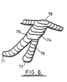
- Figure 6 shows the lower half of a restraint cage 70 into which the OWFS is laid prior to inflation.
- a corresponding upper half (not shown) is hinged thereto at hinges 71, 72.
- other ways of opening the cage may be used, such as lifting the upper half or hinging along a longitudinal direction.
- the cage is formed of strip metal e.g. stainless steel, and comprises an outline 74 and hoops 76.
- the cage is open at the cuffs and at the neck, where a flange 78 is provided for attachment of the cage to the pivotting head 48.
- the cage is slightly smaller than the OWFS to avoid stretching the OWFS during inflation and testing.
- the apparatus is pneumatically operated and is provided with a control box 80. Switches are provided for certain functions. Switch 82 starts the test cycle, switches 84 and 85 stop and reset. Switch 86 closes the neck clamps. Switch 88 tilts the pivotting head.
- the test procedure is substantially as before, except that the machine cycles automatically.
- the neck and cuff clamps are initially set under low pressure. Initiation of the test cycle locks the clamps under high pressure and sprays air/water mixture into the OWFS. To prevent over-inflation a vent (not shown) allows excess air to vent through the plug 4.
- a vent (not shown) allows excess air to vent through the plug 4.
- the pivotting head is raised by the operator at a chosen time via switch 88. Operation of switch 84 allows the cycle to be stopped or reset.
Landscapes
- Physics & Mathematics (AREA)
- General Physics & Mathematics (AREA)
- Examining Or Testing Airtightness (AREA)
- Materials For Medical Uses (AREA)
- Glass Compositions (AREA)
Claims (13)
- Vorrichtung zur Dichtheitsprüfung eines KIeidungsstücks (2) auf Eintritt von flüssigem Wasser bei von innen nach außen gewendetem Kleidungsstück, wobei die Vorrichtung folgendes aufweist:- eine Verschlußeinrichtung (4, 26, 28) zum Verschließen von Öffnungen im Kleidungsstück, so daß es dem Kleidungsstück erlaubt wird, aufgepumpt zu werden;- eine Sprüheinrichtung (16, 18) zum Besprühen der Innenseite des verschlossenen Kleidungsstücks mit flüssigem Wasser; und- eine Druckbeaufschlagungseinrichtung zum Aufpumpen des verschlossenen Kleidungsstücks mittels unter Druck stehendem Gas und zum Treiben des versprühten flüssigen Wassers durch irgendwelche undichte Stellen im Kleidungsstück.
- Vorrichtung nach Anspruch 1, bei der die Verschlußeinrichtung einen Stopfen (4) zum Einpassen in den Hals des Kleidungsstücks und eine Festklemmeinrichtung (36, 38, 40, 42) zum Festklemmen des Halses an Ort und Stelle aufweist.
- Vorrichtung nach einem der vorhergehenden Ansprüche, bei dem die Spruheinrichtung Leitungen (6, 8, 10, 12, 14) zur Versorgung mit flüssigem Wasser und unter Druck gesetztem Gas aufweist, welche durch die Verschlußeinrichtung (4) laufen und in Sprühdüsen (16, 18) enden, die sich bei Anwendung im Kleidungsstück befinden.
- Vorrichtung nach Anspruch 3, bei der das Kleidungsstück ein Anzug (2) ist und die Sprühdüsen (18) die Besprühung in die Arme und Beine des Anzugs richten.
- Vorrichtung nach einem der vorhergehenden Ansprüche, die ferner eine Einrichtung (48, 50) zum Neigen des aufgepumpten Kleidungsstücks von einer im wesentlichen horizontalen Lage in eine aufrechte Lage zur Dichtheitsüberprüfung aufweist.
- Vorrichtung nach einem der vorhergehenden Ansprüche, die eine Einrichtung zur Regelung des Gasdrucks im Innern des Kleidungsstücks auf einen vorbestimmten Wert aufweist.
- Vorrichtung nach einem der vorhergehenden Ansprüche, die ferner eine Halteeinrichtung (70) zum Umschließen des Kleidungsstücks und zur Vermeidung eines Überdehnens des Kleidungsstücks während des Aufpumpens aufweist; wobei die Halteeinrichtung eine offene oder durchsichtige Bauweise aufweist, welche eine Überprüfung von undichten Stellen gestattet.
- Vorrichtung nach Anspruch 7, bei der die Halteeinrichtung in der Form eines starren Käfigs (70) ist.
- Vorrichtung nach Anspruch 7 oder 8, bei der die Halteeinrichtung (70) kleiner als das Kleidungsstück ist, um ein Überdehnen zu vermeiden.
- Vorrichtung nach Anspruch 1, bei der die Verschlußeinrichtung einen Stopfen (4) zum Einpassen in eine Öffnung im Kleidungsstück und eine Festklemmeinrichtung (36, 38, 40, 42) zum Festklemmten der Kleidungsstücköffnung um den Stopfen herum aufweist und bei dem die Sprüheinrichtung Leitungen (44, 46) zur Versorgung mit flüssigem Wasser und unter Druck gesetztem Gas aufweist, welche durch den Verschlußstopfen laufen und in Sprühdüsen (18) enden, die sich bei Anwendung im Kleidungsstück befinden.
- Ein Verfahren zur Dichtheitsprüfung eines wasserfesten Kleidungsstücks auf Eintritt von flüssigem Wasser, welches folgendes aufweist:- Verschließen von Öffnungen im Kleidungsstück, so daß dem Kleidungsstück erlaubt wird, aufgepumpt zu werden;- simultanes oder sequentielles Druckbeaufschlagen und Aufpumpen des verschlossenen Kleidungsstücks mittels unter Druck stehendem Gas und Besprühen der Innenseite des verschlossenen Kleidungsstücks mit flüssigem Wasser; und- Untersuchen der Oberfläche des aufgepumpten Kleidungsstücks auf durch irgendwelche undichte Stellen in dem Kleidungsstück getriebenes flüssiges Wasser.
- Verfahren nach Anspruch 11, bei dem das Kleidungsstück zuerst im wesentlichen in einer horizontalen Lage aufgepumpt und dann in eine aufrechte Lage geschwenkt wird.
- Verfahren nach einem der Ansprüche 11 und 12, welches ferner den Schritt aufweist, eine im wesentlichen unelastische Halteeinrichtung um das Kleidungsstück herum vorzusehen, um ein Überdehnen während des Aufpumpens zu verhindern.
Applications Claiming Priority (3)
| Application Number | Priority Date | Filing Date | Title |
|---|---|---|---|
| GB9123880 | 1991-11-09 | ||
| GB919123880A GB9123880D0 (en) | 1991-11-09 | 1991-11-09 | Leak testing |
| PCT/GB1992/002060 WO1993009418A1 (en) | 1991-11-09 | 1992-11-09 | Leak testing |
Publications (2)
| Publication Number | Publication Date |
|---|---|
| EP0611444A1 EP0611444A1 (de) | 1994-08-24 |
| EP0611444B1 true EP0611444B1 (de) | 1996-10-02 |
Family
ID=10704398
Family Applications (1)
| Application Number | Title | Priority Date | Filing Date |
|---|---|---|---|
| EP92923172A Expired - Lifetime EP0611444B1 (de) | 1991-11-09 | 1992-11-09 | Leckprüfung |
Country Status (10)
| Country | Link |
|---|---|
| US (1) | US5390531A (de) |
| EP (1) | EP0611444B1 (de) |
| JP (1) | JPH07502595A (de) |
| AU (1) | AU665217B2 (de) |
| CA (1) | CA2121130A1 (de) |
| DE (1) | DE69214293T2 (de) |
| FI (1) | FI942101A0 (de) |
| GB (2) | GB9123880D0 (de) |
| NO (1) | NO941691L (de) |
| WO (1) | WO1993009418A1 (de) |
Cited By (1)
| Publication number | Priority date | Publication date | Assignee | Title |
|---|---|---|---|---|
| CN112067210A (zh) * | 2020-09-18 | 2020-12-11 | 潘彬杰 | 一种基于密封防护服安全检测的布料密封性检测装置 |
Families Citing this family (20)
| Publication number | Priority date | Publication date | Assignee | Title |
|---|---|---|---|---|
| GB2265721B (en) * | 1992-04-03 | 1995-11-08 | Gore & Ass | Leak testing waterproof outer footwear |
| US5517849A (en) * | 1994-12-15 | 1996-05-21 | Carter-Wallace, Inc. | Apparatus and method including porous liner for testing for holes in prophylactic devices |
| DE19533443C1 (de) * | 1995-09-09 | 1997-04-03 | Lobbe Xenex Gmbh & Co | Vorrichtung zur Desinfektion und Trocknung von Vollschutzanzügen |
| US5887477A (en) * | 1997-04-15 | 1999-03-30 | Nike, Inc. | Apparatus and method for testing waterproofness and breathing fabrics |
| KR100236717B1 (ko) * | 1997-12-24 | 2000-01-15 | 윤종용 | 크린룸용 방진복의 파티클발생 분석장치 및 이를 이용한 파티클분석방법 |
| US6430989B1 (en) * | 2000-12-29 | 2002-08-13 | Kimberly-Clark Worldwide, Inc. | Method and apparatus for evaluating swimwear for underwater leakage |
| DE10261354A1 (de) * | 2002-12-30 | 2004-07-08 | BSH Bosch und Siemens Hausgeräte GmbH | Lebensdauerprüfung und entsprechende Vorrichtung für Bügeltextilien |
| US7704598B2 (en) * | 2004-05-26 | 2010-04-27 | Gore Enterprise Holdings, Inc. | Durable covering for chemical protection |
| US20050274751A1 (en) * | 2004-06-14 | 2005-12-15 | Aric Plumley | Wetsuit rinsing hanger |
| US7587929B2 (en) * | 2005-09-09 | 2009-09-15 | Scot Incorporated | Joint combined aircrew systems tester |
| US8281644B2 (en) | 2010-06-02 | 2012-10-09 | Jim Quentin Nichols | Hydrostatic tester |
| JP5464592B2 (ja) * | 2010-06-14 | 2014-04-09 | 株式会社重松製作所 | 化学防護服の気密試験方法 |
| CN102445308B (zh) * | 2011-09-30 | 2014-10-29 | 太仓市锐杰实验仪器制造有限公司 | 喷溅液密度测试仪 |
| DE102015108857A1 (de) * | 2015-06-03 | 2016-12-08 | Rud. Prey Gmbh & Co. Kg | Verfahren und System zur Pflege mindestens eines Schutzanzugs |
| US10288543B2 (en) | 2016-01-16 | 2019-05-14 | Columbia Insurance Company | Methods for determining moisture permeability in textiles |
| CN109163860B (zh) * | 2018-07-30 | 2020-03-27 | 新乡市新科防护科技有限公司 | 一种潜水服用密封性检测装置 |
| IT202000004468A1 (it) * | 2020-03-03 | 2021-09-03 | Macpi Spa Pressing Div | Semilavorato in maglia per la fabbricazione di calze, calzature e guanti e processo per la sua realizzazione |
| AT523613B1 (de) * | 2020-03-11 | 2022-04-15 | Kriegl Maximilian | Trocknungsvorrichtung zum Trocknen eines Schutzanzuges |
| US11788918B2 (en) | 2020-06-18 | 2023-10-17 | Trevillyan Labs, Llc | Fluid detection fabric |
| CN117232737B (zh) * | 2023-11-16 | 2024-01-23 | 济南鑫鑫体育用品有限公司 | 一种篮球生产漏气检测装置 |
Family Cites Families (12)
| Publication number | Priority date | Publication date | Assignee | Title |
|---|---|---|---|---|
| US2126434A (en) * | 1937-08-19 | 1938-08-09 | Kenneth S Vosbury | Glove testing device |
| US2800788A (en) * | 1956-05-14 | 1957-07-30 | Willard H Smith | Glove testing apparatus |
| US3315519A (en) * | 1964-04-13 | 1967-04-25 | American Sterilizer Co | Surgical glove leak tester |
| DE2533830A1 (de) * | 1975-07-29 | 1977-02-10 | Leybold Heraeus Gmbh & Co Kg | Einrichtung zur lecksuche an prueflingen mit leicht verformbaren wandungen |
| GB2111824A (en) * | 1981-12-22 | 1983-07-13 | Multifabs Ltd | Protective garments |
| JPH0627216B2 (ja) * | 1984-12-11 | 1994-04-13 | ジャパンゴアテックス株式会社 | 伸縮性をもった衣料用透湿防水性フィルム |
| US4612798A (en) * | 1985-07-01 | 1986-09-23 | Simon Roberts | Pneumatic tire leak detector and method |
| US4776209A (en) * | 1987-07-13 | 1988-10-11 | W. L. Gore & Associates, Inc. | Leakage detector |
| US4885930A (en) * | 1988-08-30 | 1989-12-12 | The United States Of America As Represented By The Secretary Of The Navy | Garment pressurizing apparatus |
| US4969350A (en) * | 1989-04-12 | 1990-11-13 | International Marketing Inc. | Method of inspecting tires for defects |
| GB9020703D0 (en) * | 1990-09-22 | 1990-11-07 | Multifabs Ltd | Improvements in or relating to valves |
| US5327775A (en) * | 1992-10-27 | 1994-07-12 | Yakov Epshteyn | Condom tester and applicator |
-
1991
- 1991-11-09 GB GB919123880A patent/GB9123880D0/en active Pending
-
1992
- 1992-11-06 GB GB9223353A patent/GB2261291B/en not_active Revoked
- 1992-11-09 AU AU28994/92A patent/AU665217B2/en not_active Ceased
- 1992-11-09 WO PCT/GB1992/002060 patent/WO1993009418A1/en not_active Ceased
- 1992-11-09 US US08/232,077 patent/US5390531A/en not_active Expired - Lifetime
- 1992-11-09 CA CA002121130A patent/CA2121130A1/en not_active Abandoned
- 1992-11-09 JP JP5508290A patent/JPH07502595A/ja active Pending
- 1992-11-09 DE DE69214293T patent/DE69214293T2/de not_active Expired - Fee Related
- 1992-11-09 EP EP92923172A patent/EP0611444B1/de not_active Expired - Lifetime
-
1994
- 1994-05-06 FI FI942101A patent/FI942101A0/fi unknown
- 1994-05-06 NO NO941691A patent/NO941691L/no unknown
Cited By (1)
| Publication number | Priority date | Publication date | Assignee | Title |
|---|---|---|---|---|
| CN112067210A (zh) * | 2020-09-18 | 2020-12-11 | 潘彬杰 | 一种基于密封防护服安全检测的布料密封性检测装置 |
Also Published As
| Publication number | Publication date |
|---|---|
| DE69214293D1 (de) | 1996-11-07 |
| GB2261291B (en) | 1995-01-25 |
| FI942101A7 (fi) | 1994-05-06 |
| DE69214293T2 (de) | 1997-04-24 |
| AU2899492A (en) | 1993-06-07 |
| GB9223353D0 (en) | 1992-12-23 |
| GB2261291A (en) | 1993-05-12 |
| FI942101A0 (fi) | 1994-05-06 |
| CA2121130A1 (en) | 1993-05-13 |
| WO1993009418A1 (en) | 1993-05-13 |
| AU665217B2 (en) | 1995-12-21 |
| EP0611444A1 (de) | 1994-08-24 |
| JPH07502595A (ja) | 1995-03-16 |
| US5390531A (en) | 1995-02-21 |
| NO941691D0 (no) | 1994-05-06 |
| NO941691L (no) | 1994-05-06 |
| GB9123880D0 (en) | 1992-01-02 |
Similar Documents
| Publication | Publication Date | Title |
|---|---|---|
| EP0611444B1 (de) | Leckprüfung | |
| US4799384A (en) | Bootie testing machine | |
| EP2200459B1 (de) | Schutzunterwäsche | |
| US20050193472A1 (en) | Chemical and biological protective hood assembly | |
| EP1294245B1 (de) | Kleidungstück und futterstruktur | |
| US20160044980A1 (en) | Breathable waterproof garment | |
| CN112924102B (zh) | 防护服质量检测设备 | |
| US5279287A (en) | Coveralls for protection against flash fires | |
| US20240228041A9 (en) | Protective Aviation Garment | |
| US8925112B2 (en) | Aircrew ensembles | |
| US6910229B2 (en) | Inflatable insulation incorporating pressure relief means | |
| US9708061B2 (en) | Aircrew ensembles | |
| CN211417554U (zh) | 不湿身救生衣 | |
| CN212414877U (zh) | 一种特种设备检验人员专用服 | |
| WO2012041974A1 (en) | Aircrew ensembles | |
| CN215043570U (zh) | 一种水域救援用高强度干式救援服 | |
| CN121917423A (zh) | 一种防化服整体抗水渗漏性试验设备及方法 | |
| US20250304253A1 (en) | Inflatable bladder for aircrew anti-g garment | |
| GB2320413A (en) | Protective garment | |
| CN114712742A (zh) | 基于消防使用的具备喷水灭火功能的防火服 | |
| Jung-Sook | A Study on the Wearing Comfort of Firefighter's Protective Clothing | |
| GB2416667A (en) | Rubber attachments for diving suits | |
| DONNING et al. | Technical Manual | |
| Iacono et al. | Chemical Protective Suit Environmental Protection Agency |
Legal Events
| Date | Code | Title | Description |
|---|---|---|---|
| PUAI | Public reference made under article 153(3) epc to a published international application that has entered the european phase |
Free format text: ORIGINAL CODE: 0009012 |
|
| 17P | Request for examination filed |
Effective date: 19940328 |
|
| AK | Designated contracting states |
Kind code of ref document: A1 Designated state(s): DE FR GB IT SE |
|
| 17Q | First examination report despatched |
Effective date: 19950508 |
|
| GRAG | Despatch of communication of intention to grant |
Free format text: ORIGINAL CODE: EPIDOS AGRA |
|
| GRAH | Despatch of communication of intention to grant a patent |
Free format text: ORIGINAL CODE: EPIDOS IGRA |
|
| GRAH | Despatch of communication of intention to grant a patent |
Free format text: ORIGINAL CODE: EPIDOS IGRA |
|
| GRAA | (expected) grant |
Free format text: ORIGINAL CODE: 0009210 |
|
| AK | Designated contracting states |
Kind code of ref document: B1 Designated state(s): DE FR GB IT SE |
|
| ITF | It: translation for a ep patent filed | ||
| REF | Corresponds to: |
Ref document number: 69214293 Country of ref document: DE Date of ref document: 19961107 |
|
| ET | Fr: translation filed | ||
| PLBE | No opposition filed within time limit |
Free format text: ORIGINAL CODE: 0009261 |
|
| STAA | Information on the status of an ep patent application or granted ep patent |
Free format text: STATUS: NO OPPOSITION FILED WITHIN TIME LIMIT |
|
| 26N | No opposition filed | ||
| PGFP | Annual fee paid to national office [announced via postgrant information from national office to epo] |
Ref country code: FR Payment date: 19981020 Year of fee payment: 7 |
|
| PGFP | Annual fee paid to national office [announced via postgrant information from national office to epo] |
Ref country code: SE Payment date: 19981021 Year of fee payment: 7 Ref country code: GB Payment date: 19981021 Year of fee payment: 7 |
|
| PGFP | Annual fee paid to national office [announced via postgrant information from national office to epo] |
Ref country code: DE Payment date: 19981022 Year of fee payment: 7 |
|
| PG25 | Lapsed in a contracting state [announced via postgrant information from national office to epo] |
Ref country code: GB Free format text: LAPSE BECAUSE OF NON-PAYMENT OF DUE FEES Effective date: 19991109 |
|
| PG25 | Lapsed in a contracting state [announced via postgrant information from national office to epo] |
Ref country code: SE Free format text: LAPSE BECAUSE OF NON-PAYMENT OF DUE FEES Effective date: 19991110 |
|
| GBPC | Gb: european patent ceased through non-payment of renewal fee |
Effective date: 19991109 |
|
| EUG | Se: european patent has lapsed |
Ref document number: 92923172.8 |
|
| PG25 | Lapsed in a contracting state [announced via postgrant information from national office to epo] |
Ref country code: FR Free format text: LAPSE BECAUSE OF NON-PAYMENT OF DUE FEES Effective date: 20000731 |
|
| PG25 | Lapsed in a contracting state [announced via postgrant information from national office to epo] |
Ref country code: DE Free format text: LAPSE BECAUSE OF NON-PAYMENT OF DUE FEES Effective date: 20000901 |
|
| REG | Reference to a national code |
Ref country code: FR Ref legal event code: ST |
|
| PG25 | Lapsed in a contracting state [announced via postgrant information from national office to epo] |
Ref country code: IT Free format text: LAPSE BECAUSE OF NON-PAYMENT OF DUE FEES;WARNING: LAPSES OF ITALIAN PATENTS WITH EFFECTIVE DATE BEFORE 2007 MAY HAVE OCCURRED AT ANY TIME BEFORE 2007. THE CORRECT EFFECTIVE DATE MAY BE DIFFERENT FROM THE ONE RECORDED. Effective date: 20051109 |