EP0611491B1 - Satellitenantennen und Strahlsteuerungsmethoden für Satelliten-Kommunikationssystem - Google Patents
Satellitenantennen und Strahlsteuerungsmethoden für Satelliten-Kommunikationssystem Download PDFInfo
- Publication number
- EP0611491B1 EP0611491B1 EP92925035A EP92925035A EP0611491B1 EP 0611491 B1 EP0611491 B1 EP 0611491B1 EP 92925035 A EP92925035 A EP 92925035A EP 92925035 A EP92925035 A EP 92925035A EP 0611491 B1 EP0611491 B1 EP 0611491B1
- Authority
- EP
- European Patent Office
- Prior art keywords
- antenna
- earth
- time delay
- beams
- satellite
- Prior art date
- Legal status (The legal status is an assumption and is not a legal conclusion. Google has not performed a legal analysis and makes no representation as to the accuracy of the status listed.)
- Expired - Lifetime
Links
- 238000004891 communication Methods 0.000 title abstract description 23
- 238000000034 method Methods 0.000 title abstract description 12
- 229910001218 Gallium arsenide Inorganic materials 0.000 claims description 5
- 230000008859 change Effects 0.000 claims description 2
- JBRZTFJDHDCESZ-UHFFFAOYSA-N AsGa Chemical compound [As]#[Ga] JBRZTFJDHDCESZ-UHFFFAOYSA-N 0.000 description 5
- 238000010586 diagram Methods 0.000 description 4
- 238000013461 design Methods 0.000 description 3
- 230000037361 pathway Effects 0.000 description 3
- 230000005855 radiation Effects 0.000 description 3
- 238000003491 array Methods 0.000 description 2
- 230000005540 biological transmission Effects 0.000 description 2
- 230000001413 cellular effect Effects 0.000 description 2
- 238000005562 fading Methods 0.000 description 2
- 238000012545 processing Methods 0.000 description 2
- 238000001228 spectrum Methods 0.000 description 2
- 239000011157 advanced composite material Substances 0.000 description 1
- 230000001174 ascending effect Effects 0.000 description 1
- 230000010267 cellular communication Effects 0.000 description 1
- 230000001934 delay Effects 0.000 description 1
- 238000011161 development Methods 0.000 description 1
- 239000003365 glass fiber Substances 0.000 description 1
- 238000005286 illumination Methods 0.000 description 1
- 238000013507 mapping Methods 0.000 description 1
- 239000000463 material Substances 0.000 description 1
- 238000012986 modification Methods 0.000 description 1
- 230000004048 modification Effects 0.000 description 1
- 230000003287 optical effect Effects 0.000 description 1
- 238000009304 pastoral farming Methods 0.000 description 1
- 230000009467 reduction Effects 0.000 description 1
- 238000011160 research Methods 0.000 description 1
- 230000003595 spectral effect Effects 0.000 description 1
Images




Classifications
-
- H—ELECTRICITY
- H01—ELECTRIC ELEMENTS
- H01Q—ANTENNAS, i.e. RADIO AERIALS
- H01Q1/00—Details of, or arrangements associated with, antennas
- H01Q1/27—Adaptation for use in or on movable bodies
- H01Q1/28—Adaptation for use in or on aircraft, missiles, satellites, or balloons
- H01Q1/288—Satellite antennas
-
- B—PERFORMING OPERATIONS; TRANSPORTING
- B64—AIRCRAFT; AVIATION; COSMONAUTICS
- B64G—COSMONAUTICS; VEHICLES OR EQUIPMENT THEREFOR
- B64G1/00—Cosmonautic vehicles
- B64G1/22—Parts of, or equipment specially adapted for fitting in or to, cosmonautic vehicles
-
- H—ELECTRICITY
- H01—ELECTRIC ELEMENTS
- H01Q—ANTENNAS, i.e. RADIO AERIALS
- H01Q25/00—Antennas or antenna systems providing at least two radiating patterns
-
- H—ELECTRICITY
- H04—ELECTRIC COMMUNICATION TECHNIQUE
- H04B—TRANSMISSION
- H04B7/00—Radio transmission systems, i.e. using radiation field
- H04B7/14—Relay systems
- H04B7/15—Active relay systems
- H04B7/204—Multiple access
- H04B7/2041—Spot beam multiple access
Definitions
- the present invention relates to the field of satellite communications. More particularly, this invention provides an advanced, active element, phased array satellite antenna system which provides extremely high gain, but which also uses the available spectrum with great efficiency.
- the power supplied by the invention enables telephone users on the ground to communicate directly with a constellation of spacecraft in low Earth orbit using a compact, hand-held terminal which does not pose radiation hazards.
- the system comprises a centrally located base station which covers the surrounding service region with a plurality of scanning pencil beams operating with a Time Division Multiple Access assignment.
- an apparatus for providing radiated beams directed towards the Earth's surface and capable of communicating directly with a plurality of portable, mobile and fixed terminals, gateways and satellites comprising a plurality of antenna surfaces coupled and arranged in a generally contiguous pattern, each antenna surface being capable of generating a plurality of radiated beams which are electronically steered to footprint regions on the surface of the Earth, wherein each antenna surface has a plurality of radiating elements and incorporates a time delay active lens comprising a plurality of time delay networks, connected to respective radiating elements, and a time delay control to change the radius of the radiated beam, the arrangement being capable of producing a beam of circular or elliptical shape.
- Apparatus according to the present invention comprises an advanced active element phased array antenna and utilizes electronic beam steering to provide extremely high gain signals.
- the present invention is a vital element of a novel Satellite Communication System, which is referred to above.
- the innovative design of one of the preferred embodiments employs a hemispherical configuration of hexagonal antenna facets fabricated from ultra-light weight honeycomb materials and advanced composites.
- Gallium-arsenide (GaAs) millimeter wave integrated circuits (MMIC) coupled to each antenna panel handle call traffic.
- GaAs gallium-arsenide
- MMIC millimeter wave integrated circuits
- Each antenna simultaneously generates 256 beams which are electronically steered to 4,096 portions on the surface of the Earth.
- Each individual beam illuminates a region on the ground that measures roughly twenty kilometers by twenty kilometers.
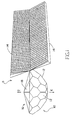
- Figure 1 is perspective view of a satellite that includes a hemispherical array of hexagonal antenna facets and fully extended rectangular solar panels.
- Figure 2 depicts a schematic diagram of the satellite similar to the one illustrated in Figure 1.
- Figure 2 also reveals three sets of electronically steered beams produced by the hexagonal antennas and the circular and elliptical footprints which the beams illuminate on the Earth's surface.
- Figure 3 presents a schematic depiction of the pattern of multiple beams generated by the satellite shown in Figures 1 and 2.
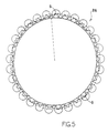
- Figures 4 and 5 are plots that reveal the geometric relationship of several spacecraft traveling in one of the many orbital planes in the satellite constellation.
- the pathways between neighboring satellites that are not occluded by the limb of the Earth provide communication links between spacecraft in the same orbit.
- Figure 6 reveals a schematic diagram of a GaAs MMIC time delay network.
- Figure 7 shows a schematic of the active lens, which includes a large number of the time delay networks shown in Figure 6.
- Figure 8 is a schematic illustration of an active lens which incorporates a time delay steered antenna array.
- FIG. 1 depicts one of the preferred embodiments of the antennas.
- This perspective schematic view shows a satellite S that includes an array 10 of generally hexagonal antenna Earth-facing facets 12 that are mated together along their six-sided boundaries to form a slightly flattened, hemispherical shell.
- a space-facing array 16 that includes facets 18 is mated to the Earth facing array 10.
- the antenna shell is connected to two generally rectilinear, unfurled, solar panels 14 which trail the body of the spacecraft S.
- Figure 2 depicts a schematic diagram of a similar satellite S, and also reveals three sets of electronically steered beams 19 produced by the hexagonal antennas 12 and the circular and elliptical footprints 20 which the beams 19 illuminate on the Earth's surface.
- the footprints 20 of the radio beams 19 are shown as regions of "illumination" on various portions of the Earth's surface E.
- These beams provide communications services to subscribers using portable (P), mobile (M) and fixed (F) terminals and gateways (G).
- P portable
- M mobile
- F fixed terminals and gateways
- the set of beams marked 19a travel the shortest possible distance from the spacecraft S to the Earth E because these beams 19a travel along a pathway which runs from the ground to the zenith Z and back.
- the area on the surface illuminated by this set of beams 19a results in a generally circular footprint 20a.
- Other sets of beams like those marked 19b and 19c, are more inclined to the line that runs from the center of the Earth toward the zenith Z, and the areas 20b and 20c irradiated by these beams 19b and 19c, unless connected, become progessively more elliptical as the angle of inclination becomes larger.
- Figure 3 combines many sets of beams and portrays a complete set of line-of-sight radio waves 22 generated by one spacecraft.
- Figures 4 and 5 are geometric plots 24 and 26 which include sight lines between neighboring satellites that travel along the same orbit. These plots 24 and 26 reveal the geometric relationship of several spacecraft S traveling in one of the many orbital planes in the satellite constellation. The pathways between neighboring satellites that are not occluded by the limb of the Earth provide communication links between spacecraft S in the same orbit.
- the satellites shown in Figures 1 and 2 operate in a constellation which includes 29 sets of spacecraft flying in 29 orbits. The entire fleet travels around the Earth at a height of 700 km (435 miles).
- the antenna facets or surfaces 12 are designed to transmit and receive signals from terrestrial units that are located within the footprints 20 produced by the electronically steered beams 19. Only those terrestrial units that are within the conical line-of-sight region that is defined by a minimum elevation angle, or "mask angle,” of 40 degrees can be serviced by a particular spacecraft.
- the hexagonal antenna facets 12 and their related signal processing circuitry produce a hexagonal coverage pattern.
- the radius to the center of each of the six sides of each facet 12 is 6.2 degrees, while the radius to the six corners of the hexagon subtends 7.16 degrees.
- a spacing of 12.41 degrees allows for 29 hexagonal coverage patterns in each orbital plane.
- a similar spacing along the equator results in 29 orbital planes.
- This configuration of hexagonal facets 12 offers double coverage in the equatorial regions and up to eight-fold coverage at higher latitudes, where larger numbers of subscribers are located.
- the center of the descending patterns will fall on the seams of the ascending patterns. This selection insures that virtually every region on the surface between the latitudes of 70 degrees North and South will be serviced by the constellation.
- the spaceborne antenna facets or surfaces 12 are capable of providing a gain of 45 dB at the periphery of each footprint and 42 dB at the nadir position. Because the beams generated by the spaceborne antenna facets 12 are so powerful, Earth-based terminals can incorporate low power antenna designs which substantially eliminate any radiation hazards that might otherwise harm the user. Each antenna uses a combination of the 20 and 30 Ghz frequency bands for satellite to ground communications, and propagates 256 simultaneous beams, which are multiplexed to 4,096 positions. Beams aimed at the horizon possess an elliptical, as opposed to a circular or polygonal, shape to compensate for the low grazing angle, so that a constant Earth coverage footprint is maintained.
- Uncorrected beams have an elliptical ground pattern which degrades spectral reuse efficiency.
- Electronic beam steering also permits the independent control of directivity gain and power gain.
- the beam steering provides a convenient method of correcting power levels during rain fades.
- the transmitted power gain from the satellite can be increased on transmit to overcome downlink fading.
- Satellite receive power gain can be increased during receive to overcome uplink fading. The use of these two techniques overcomes possibly poor communication performance during rainy weather conditions.
- Signal processing components residing in the spacecraft include GaAs MMIC filters and are responsible for electronically steering active antenna arrays on board each satellite.
- Figure 6 reveals a schematic diagram of a GaAs MMIC time delay network 28.
- Figure 7 shows a schematic of the active lens 30, which includes a large number of the time delay networks 28 coupled to radiating elements 32.
- a circuit Model No. TD101 produced by Pacific Monolithics, Inc. in California is employed as the time delay network.
- Other more conventional time delay networks may also be employed.
- the electronic steering is accomplished by using these time delay networks 28 to create an active lens 30.
- the focal point of the lens 30 is related to the directivity gain of the antenna facet 12 and can be controlled electronically.
- the ability to control the directivity gain is important for communications satellites in low Earth orbit because less gain is needed when a cell is addressed at the satellite Nadir than when a cell is addressed at the periphery of the satellite footprint 20. It is also desirable to increase the directivity gain in the elevation plane when addressing a cell at the satellite footprint periphery.
- the active lens 30 incorporated in the antenna facets 12 allows these variable directivity gains to be implemented without the reduction in efficiency that is associated with conventional antenna arrays.
- the active lens 30 illustrated in Figure 7 is the microwave analog of an optical lens. By increasing the time delay for the signal paths in the center of the lens with respect to the edge of the lens, the focal length of the lens can be changed electronically, which, in turn, changes the directivity gain of the antenna facets 12.
- the antenna facets 12 provide electronic steering which is sufficiently accurate to implement a practical gain variation in the 42 dB to 45 dB regime. For example, changing the radius of a radiation pattern by 200 meters at a range of 1200 kilometers requires a time delay control of 4 picoseconds for a 45 dB gain antenna array with dimensions of 1.2 meters on a side. Active lens control for the 42 to 45 dB range (in a 20/30 GHz system) requires time delays on the order of 4 picoseconds to 35 picoseconds.
- the active lens 30 can be constructed using one of two techniques.
- the first which is depicted in Figure 7, utilizes a conventional lens that includes many pairs of receive and transmit antennas that are each connected in series with an active time delay network.
- the second technique which comprises the preferred embodiment of the invention, is a time delay circuit 34 exhibited in Figure 8.
- This circuit 34 includes a feed 36 coupled to a time delay steered array 37 which comprises a series of switches 38, time delay paths 40, transmission lines 42 and amplifiers 44.
- the time delay steered array 37 is connected to the time delay active lens 30 and to radiating elements 32.
- the switched time delay networks 28 in the corporate feed accomplish beam steering functions.
- the time delay networks 28 can be adjusted for either fine gain beam steering (a few degrees) or for changing the directivity gain of the antenna (focal length of the lens).
- Every satellite S controls the assignment of channels to terminals requesting services.
- the satellites monitor the signal quality and select which one is best suited to handle the call to the terminal.
- the receive beam from the ground terminal lags the transmit beam emitted from the satellite by a fixed interval.
- the terminal transmits its data to the satellite at a delay specified by the satellite in its preceding scan. This method is used to compensate for delay differences caused by variations in path lengths.
- the scan pattern among beams is coordinated to insure that all cells being scanned at one instant are separated by sufficient distance to eliminate interference among many closely-spaced customers.
- An electronic pushbroom carries the beams through one beam position in the direction of satellite travel, and then performs a flyback.
- Each beam carries a pilot tone which identifies each beam for terrestrial terminals.
- Components on board each satellite measure time delay and Doppler shift of each subscriber signal to determine the location of the subscriber within a particular beam footprint. Because the satellite antennas operate at a relatively high gain, the footprints on the ground are relatively small. Since the cells are small and the satellite footprint moves rapidly over the Earth's surface, any particular terminal remains in the same cell for only a few seconds. To avoid the rapid handoff from satellite to satellite every few seconds, the innovative logical/physical cell mapping scheme described in the copending patent application on Beam Compensation is utilized in conjunction with the present invention.
- Satellites communicate among one another using a 60 Ghz inter-satellite frequency band.
- a 1.5 foot antenna provides approximately 45 Db of gain which supports a practical inter-satellite link (ISL).
- ISL inter-satellite link
- Four fixed and two electronically steerable antennas are used on each satellite for ISL links.
- Optional links in the orbital plane may increase the number of ISL antennas to ten, eight of which would be fixed and two of which would be steerable.
- a second preferred embodiment comprises satellites circling in 21 orbital planes with 40 satellites S in each orbit.
- This 21 x 40 embodiment can be implemented using the same antenna facets 12 which may be modified to account for the increased population of the constellation.
- the Spacecraft Antennas and Beam Steering Methods for Satellite Communication System described above will help to overcome the limits that circumscribe the performance and potential of existing telephone systems.
- the present invention is capable of offering continuous voice, data and video service to customers across the globe on the land, on the sea, or in the air. Instead of merely improving upon or expanding existing land-based systems, the present invention bypasses centralized terrestrial switching hardware by placing all the intelligence of the network in orbit. Unlike conventional hierarchical systems, which are linked together by a complex web of wires, cables, glass fibers, and microwave repeaters that are very expensive to build and maintain, the present invention liberates the true communications potential of existing land-based networks by routing signals through spacecraft in low Earth orbit. The present invention will revolutionize the telecommunications industry, and offer a wide spectrum of services and industrial opportunities around the world.
Landscapes
- Engineering & Computer Science (AREA)
- Remote Sensing (AREA)
- Physics & Mathematics (AREA)
- Astronomy & Astrophysics (AREA)
- General Physics & Mathematics (AREA)
- Aviation & Aerospace Engineering (AREA)
- Computer Networks & Wireless Communication (AREA)
- Signal Processing (AREA)
- Radio Relay Systems (AREA)
- Variable-Direction Aerials And Aerial Arrays (AREA)
Claims (7)
- Vorrichtung zum Bereitstellen von ausgestrahlten Strahlen (19), welche in Richtung der Oberfläche der Erde gerichtet ist und in der Lage ist, direkt zu kommunizieren mit einer Mehrzahl von tragbaren (P), mobilen (M) und festen (F) Anschlußeinheiten, Überleiteinrichtungen (G) und Satelliten (S), umfassend eine Mehrzahl von Antennenflächen (12), die in einem im großen und ganzen aufeinanderfolgenden Muster angekoppelt und angeordnet sind, wobei jede Antennenfläche (12) in der Lage ist, eine Mehrzahl von ausgestrahlten Strahlen (19) zu erzeugen, die elektronisch gelenkt werden zu Ausleuchtgebieten (20) auf der Oberfläche der Erde (E), wobei jede Antennenfläche (12) eine Mehrzahl von abstrahlenden Elementen (32) aufweist und eine zeitverzögerungsaktive Linse (30) umfaßt, die eine Mehrzahl von Zeitverzögerungs-Netzwerken (28) umfaßt, welche eine Verbindung haben zu entsprechenden abstrahlenden Elementen (32), und eine Zeitverzögerungskontrolle, um den Radius des abgestrahlten Strahls zu ändern, wobei die Anordnung in der Lage ist, einen Strahl mit zirkularer oder elliptischer Form zu erzeugen.
- Vorrichtung nach Anspruch 1, wobei die Netzwerke (28) GaAs-MMIC-Zeitverzögerungs-Netzwerke umfassen.
- Vorrichtung nach Anspruch 1 oder 2, wobei die Antennenflächen (12) im wesentlichen hexagonal in der Form sind.
- Vorrichtung nach einem der vorangehenden Ansprüche, wobei die Antennenflächen (12) jeweils in der Lage sind, Strahlen (19) zu emittieren und zu empfangen über einen Kegel, welcher mindestens 25 Grad mißt.
- Vorrichtung nach einem der vorangehenden Ansprüche, wobei eine zeitverzögerungs-gelenkte Anordnung (37) mit der Linse (30) verbunden ist.
- Vorrichtung nach Anspruch 4, wobei die Anordnung (37) eine Folge von Schaltern (38) und Verzögerungspfaden (40) umfaßt.
- Vorrichtung nach einem der vorangehenden Ansprüche, wobei diese mindestens 14 Antennenflächen (12) umfaßt, die ein Muster bilden, welches sich an die Kontur einer teilweise abgeplatteten Halbkugel annähert, wobei jede Fläche in der Lage ist, gleichzeitig mindestens 256 Strahlen (19) zu erzeugen, die elektronisch auf ungefähr 4096 Positionen auf der Oberfläche der Erde (E) gelenkt werden können, wobei jeder Strahl ein Ausleuchtgebiet (20) auf der Erde ausleuchtet, welches ungefähr 20 Kilometer auf 20 Kilometer bei einer Verstärkung von mindestens 40 dB mißt, und jede Fläche (12) hat eine Mehrzahl von Paaren von Antennen zum getrennten Senden und Empfangen von jedem der Strahlen (19).
Applications Claiming Priority (3)
| Application Number | Priority Date | Filing Date | Title |
|---|---|---|---|
| US79027191A | 1991-11-08 | 1991-11-08 | |
| US790271 | 1991-11-08 | ||
| PCT/US1992/009287 WO1993009578A1 (en) | 1991-11-08 | 1992-11-05 | Spacecraft antennas and beam steering methods for satellite communication system |
Publications (2)
| Publication Number | Publication Date |
|---|---|
| EP0611491A1 EP0611491A1 (de) | 1994-08-24 |
| EP0611491B1 true EP0611491B1 (de) | 1997-12-29 |
Family
ID=25150169
Family Applications (1)
| Application Number | Title | Priority Date | Filing Date |
|---|---|---|---|
| EP92925035A Expired - Lifetime EP0611491B1 (de) | 1991-11-08 | 1992-11-05 | Satellitenantennen und Strahlsteuerungsmethoden für Satelliten-Kommunikationssystem |
Country Status (6)
| Country | Link |
|---|---|
| EP (1) | EP0611491B1 (de) |
| AT (1) | ATE161661T1 (de) |
| AU (1) | AU3123893A (de) |
| CA (1) | CA2121350A1 (de) |
| DE (1) | DE69223803T2 (de) |
| WO (1) | WO1993009578A1 (de) |
Families Citing this family (3)
| Publication number | Priority date | Publication date | Assignee | Title |
|---|---|---|---|---|
| US5386953A (en) * | 1991-11-08 | 1995-02-07 | Calling Communications Corporation | Spacecraft designs for satellite communication system |
| WO1994002972A1 (en) * | 1992-07-16 | 1994-02-03 | Calling Communications Corporation | Spacecraft intersatellite link for satellite communication system |
| US5527001A (en) * | 1993-06-11 | 1996-06-18 | Teledesic Corporation | Modular communication satellite |
Family Cites Families (1)
| Publication number | Priority date | Publication date | Assignee | Title |
|---|---|---|---|---|
| CA2022854C (en) * | 1989-10-02 | 1995-06-06 | Bary Robert Bertiger | Multiple beam deployable space antenna system |
-
1992
- 1992-11-05 EP EP92925035A patent/EP0611491B1/de not_active Expired - Lifetime
- 1992-11-05 CA CA002121350A patent/CA2121350A1/en not_active Abandoned
- 1992-11-05 WO PCT/US1992/009287 patent/WO1993009578A1/en not_active Ceased
- 1992-11-05 AU AU31238/93A patent/AU3123893A/en not_active Abandoned
- 1992-11-05 AT AT92925035T patent/ATE161661T1/de not_active IP Right Cessation
- 1992-11-05 DE DE69223803T patent/DE69223803T2/de not_active Expired - Fee Related
Also Published As
| Publication number | Publication date |
|---|---|
| CA2121350A1 (en) | 1993-05-13 |
| EP0611491A1 (de) | 1994-08-24 |
| WO1993009578A1 (en) | 1993-05-13 |
| DE69223803T2 (de) | 1998-07-23 |
| DE69223803D1 (de) | 1998-02-05 |
| AU3123893A (en) | 1993-06-07 |
| ATE161661T1 (de) | 1998-01-15 |
Similar Documents
| Publication | Publication Date | Title |
|---|---|---|
| US20250119203A1 (en) | System and method for high throughput fractionated satellites (htfs) for direct connectivity to and from end user devices and terminals using flight formations of small or very small satellites | |
| EP0611501B1 (de) | Strahlkompensationsverfahren für satellitenkommunikationssystem | |
| US5736959A (en) | Earth-fixed cell beam management for satellite communication system using dielectic lens-focused scanning beam antennas | |
| US5548294A (en) | Dielectric lens focused scanning beam antenna for satellite communication system | |
| US5822680A (en) | Frequency sharing for satellite communication system | |
| EP0611490B1 (de) | Bodenantennen für satellitenkommunikationssystem | |
| CA2217837C (en) | Cell-clustering arrangements and corresponding antenna patterns for wireless communication networks employing high-altitude aeronautical antenna platforms | |
| US4315262A (en) | Satellite communication system with a plurality of limited scan spot beams | |
| El-Jabu et al. | Cellular communications using aerial platforms | |
| US6173191B1 (en) | Localization of shaped directional transmitting and transmitting/receiving antenna array | |
| KR102541361B1 (ko) | 증가된 통신 용량을 갖는 위성 시스템 및 위성 시스템들의 용량을 증가시키는 방법들 | |
| EP4236085A2 (de) | Fraktionierte satelliten mit hohem durchsatz | |
| JPS63501673A (ja) | 操舵ビ−ム衛星通信システム | |
| US10623066B2 (en) | High altitude platform cellular systems | |
| US3406401A (en) | Communication satellite system | |
| WO1994002972A1 (en) | Spacecraft intersatellite link for satellite communication system | |
| WO2001020719A1 (en) | Smart antenna for airborne cellular system | |
| EP0611491A1 (de) | Satellitenantennen und Strahlsteuerungsmethoden für Satelliten-Kommunikationssystem | |
| EP0421722B1 (de) | Entfaltbares Weltraumantennensystem mit Vielfach-Strahlungskeulen | |
| US20030114102A1 (en) | System and method for providing trans-polar satellite communications | |
| EP1047211A2 (de) | Kommunikationssystem mit Satelliten mit einem hohen Elevationswinkel | |
| JPH04355522A (ja) | 衛星通信方法 | |
| RU47600U1 (ru) | Космическая система глобальной служебной спутниковой связи | |
| JPH11298393A (ja) | 無線システム |
Legal Events
| Date | Code | Title | Description |
|---|---|---|---|
| PUAI | Public reference made under article 153(3) epc to a published international application that has entered the european phase |
Free format text: ORIGINAL CODE: 0009012 |
|
| 17P | Request for examination filed |
Effective date: 19940426 |
|
| AK | Designated contracting states |
Kind code of ref document: A1 Designated state(s): AT BE CH DE DK ES FR GB GR IE IT LI NL SE |
|
| RAP1 | Party data changed (applicant data changed or rights of an application transferred) |
Owner name: TELEDESIC CORPORATION |
|
| 17Q | First examination report despatched |
Effective date: 19960424 |
|
| GRAG | Despatch of communication of intention to grant |
Free format text: ORIGINAL CODE: EPIDOS AGRA |
|
| GRAH | Despatch of communication of intention to grant a patent |
Free format text: ORIGINAL CODE: EPIDOS IGRA |
|
| GRAH | Despatch of communication of intention to grant a patent |
Free format text: ORIGINAL CODE: EPIDOS IGRA |
|
| GRAA | (expected) grant |
Free format text: ORIGINAL CODE: 0009210 |
|
| AK | Designated contracting states |
Kind code of ref document: B1 Designated state(s): AT BE CH DE DK ES FR GB GR IE IT LI NL SE |
|
| PG25 | Lapsed in a contracting state [announced via postgrant information from national office to epo] |
Ref country code: NL Free format text: LAPSE BECAUSE OF FAILURE TO SUBMIT A TRANSLATION OF THE DESCRIPTION OR TO PAY THE FEE WITHIN THE PRESCRIBED TIME-LIMIT Effective date: 19971229 Ref country code: LI Free format text: LAPSE BECAUSE OF FAILURE TO SUBMIT A TRANSLATION OF THE DESCRIPTION OR TO PAY THE FEE WITHIN THE PRESCRIBED TIME-LIMIT Effective date: 19971229 Ref country code: GR Free format text: LAPSE BECAUSE OF NON-PAYMENT OF DUE FEES Effective date: 19971229 Ref country code: ES Free format text: THE PATENT HAS BEEN ANNULLED BY A DECISION OF A NATIONAL AUTHORITY Effective date: 19971229 Ref country code: DK Free format text: LAPSE BECAUSE OF NON-PAYMENT OF DUE FEES Effective date: 19971229 Ref country code: CH Free format text: LAPSE BECAUSE OF FAILURE TO SUBMIT A TRANSLATION OF THE DESCRIPTION OR TO PAY THE FEE WITHIN THE PRESCRIBED TIME-LIMIT Effective date: 19971229 Ref country code: BE Free format text: LAPSE BECAUSE OF FAILURE TO SUBMIT A TRANSLATION OF THE DESCRIPTION OR TO PAY THE FEE WITHIN THE PRESCRIBED TIME-LIMIT Effective date: 19971229 Ref country code: AT Free format text: LAPSE BECAUSE OF FAILURE TO SUBMIT A TRANSLATION OF THE DESCRIPTION OR TO PAY THE FEE WITHIN THE PRESCRIBED TIME-LIMIT Effective date: 19971229 |
|
| REF | Corresponds to: |
Ref document number: 161661 Country of ref document: AT Date of ref document: 19980115 Kind code of ref document: T |
|
| REG | Reference to a national code |
Ref country code: CH Ref legal event code: EP |
|
| REF | Corresponds to: |
Ref document number: 69223803 Country of ref document: DE Date of ref document: 19980205 |
|
| RAP2 | Party data changed (patent owner data changed or rights of a patent transferred) |
Owner name: TELEDESIC LLC |
|
| ITF | It: translation for a ep patent filed | ||
| ET | Fr: translation filed | ||
| PG25 | Lapsed in a contracting state [announced via postgrant information from national office to epo] |
Ref country code: SE Free format text: LAPSE BECAUSE OF FAILURE TO SUBMIT A TRANSLATION OF THE DESCRIPTION OR TO PAY THE FEE WITHIN THE PRESCRIBED TIME-LIMIT Effective date: 19980329 |
|
| NLT2 | Nl: modifications (of names), taken from the european patent patent bulletin |
Owner name: TELEDESIC LLC |
|
| NLV1 | Nl: lapsed or annulled due to failure to fulfill the requirements of art. 29p and 29m of the patents act | ||
| REG | Reference to a national code |
Ref country code: IE Ref legal event code: FG4D Free format text: 78046 |
|
| REG | Reference to a national code |
Ref country code: CH Ref legal event code: PL |
|
| PG25 | Lapsed in a contracting state [announced via postgrant information from national office to epo] |
Ref country code: IE Free format text: LAPSE BECAUSE OF NON-PAYMENT OF DUE FEES Effective date: 19981105 |
|
| PLBE | No opposition filed within time limit |
Free format text: ORIGINAL CODE: 0009261 |
|
| STAA | Information on the status of an ep patent application or granted ep patent |
Free format text: STATUS: NO OPPOSITION FILED WITHIN TIME LIMIT |
|
| 26N | No opposition filed | ||
| REG | Reference to a national code |
Ref country code: GB Ref legal event code: 732E |
|
| PGFP | Annual fee paid to national office [announced via postgrant information from national office to epo] |
Ref country code: GB Payment date: 20010907 Year of fee payment: 10 |
|
| PGFP | Annual fee paid to national office [announced via postgrant information from national office to epo] |
Ref country code: DE Payment date: 20011120 Year of fee payment: 10 |
|
| REG | Reference to a national code |
Ref country code: GB Ref legal event code: IF02 |
|
| PGFP | Annual fee paid to national office [announced via postgrant information from national office to epo] |
Ref country code: FR Payment date: 20020206 Year of fee payment: 10 |
|
| PG25 | Lapsed in a contracting state [announced via postgrant information from national office to epo] |
Ref country code: FR Free format text: LAPSE BECAUSE OF NON-PAYMENT OF DUE FEES Effective date: 20020730 |
|
| REG | Reference to a national code |
Ref country code: FR Ref legal event code: ST |
|
| REG | Reference to a national code |
Ref country code: FR Ref legal event code: ST |
|
| PG25 | Lapsed in a contracting state [announced via postgrant information from national office to epo] |
Ref country code: GB Free format text: LAPSE BECAUSE OF NON-PAYMENT OF DUE FEES Effective date: 20021105 |
|
| PG25 | Lapsed in a contracting state [announced via postgrant information from national office to epo] |
Ref country code: DE Free format text: LAPSE BECAUSE OF NON-PAYMENT OF DUE FEES Effective date: 20030603 |
|
| GBPC | Gb: european patent ceased through non-payment of renewal fee | ||
| PG25 | Lapsed in a contracting state [announced via postgrant information from national office to epo] |
Ref country code: IT Free format text: LAPSE BECAUSE OF NON-PAYMENT OF DUE FEES;WARNING: LAPSES OF ITALIAN PATENTS WITH EFFECTIVE DATE BEFORE 2007 MAY HAVE OCCURRED AT ANY TIME BEFORE 2007. THE CORRECT EFFECTIVE DATE MAY BE DIFFERENT FROM THE ONE RECORDED. Effective date: 20051105 |