EP0612100B1 - Lampe à décharge à haute pression sans électrodes - Google Patents
Lampe à décharge à haute pression sans électrodes Download PDFInfo
- Publication number
- EP0612100B1 EP0612100B1 EP19940200250 EP94200250A EP0612100B1 EP 0612100 B1 EP0612100 B1 EP 0612100B1 EP 19940200250 EP19940200250 EP 19940200250 EP 94200250 A EP94200250 A EP 94200250A EP 0612100 B1 EP0612100 B1 EP 0612100B1
- Authority
- EP
- European Patent Office
- Prior art keywords
- lead
- heat sink
- electric
- live
- pressure discharge
- Prior art date
- Legal status (The legal status is an assumption and is not a legal conclusion. Google has not performed a legal analysis and makes no representation as to the accuracy of the status listed.)
- Expired - Lifetime
Links
- 229910017083 AlN Inorganic materials 0.000 claims description 20
- PIGFYZPCRLYGLF-UHFFFAOYSA-N Aluminum nitride Chemical compound [Al]#N PIGFYZPCRLYGLF-UHFFFAOYSA-N 0.000 claims description 20
- 230000007935 neutral effect Effects 0.000 claims description 17
- PNEYBMLMFCGWSK-UHFFFAOYSA-N Alumina Chemical compound [O-2].[O-2].[O-2].[Al+3].[Al+3] PNEYBMLMFCGWSK-UHFFFAOYSA-N 0.000 description 3
- 238000001816 cooling Methods 0.000 description 3
- 229910052751 metal Inorganic materials 0.000 description 3
- 239000002184 metal Substances 0.000 description 3
- RYGMFSIKBFXOCR-UHFFFAOYSA-N Copper Chemical compound [Cu] RYGMFSIKBFXOCR-UHFFFAOYSA-N 0.000 description 2
- 229910010293 ceramic material Inorganic materials 0.000 description 2
- 229910052802 copper Inorganic materials 0.000 description 2
- 239000010949 copper Substances 0.000 description 2
- 239000003989 dielectric material Substances 0.000 description 2
- 230000004048 modification Effects 0.000 description 2
- 238000012986 modification Methods 0.000 description 2
- XLYOFNOQVPJJNP-UHFFFAOYSA-N water Substances O XLYOFNOQVPJJNP-UHFFFAOYSA-N 0.000 description 2
- 229910008069 Cerium(III) iodide Inorganic materials 0.000 description 1
- 239000004642 Polyimide Substances 0.000 description 1
- VYPSYNLAJGMNEJ-UHFFFAOYSA-N Silicium dioxide Chemical compound O=[Si]=O VYPSYNLAJGMNEJ-UHFFFAOYSA-N 0.000 description 1
- ZEDZJUDTPVFRNB-UHFFFAOYSA-K cerium(3+);triiodide Chemical compound I[Ce](I)I ZEDZJUDTPVFRNB-UHFFFAOYSA-K 0.000 description 1
- 238000010276 construction Methods 0.000 description 1
- 238000005265 energy consumption Methods 0.000 description 1
- 239000012530 fluid Substances 0.000 description 1
- 150000002739 metals Chemical class 0.000 description 1
- 239000010445 mica Substances 0.000 description 1
- 229910052618 mica group Inorganic materials 0.000 description 1
- 229920001721 polyimide Polymers 0.000 description 1
- 229920001343 polytetrafluoroethylene Polymers 0.000 description 1
- 229910052594 sapphire Inorganic materials 0.000 description 1
- 239000010980 sapphire Substances 0.000 description 1
- 239000002470 thermal conductor Substances 0.000 description 1
Images

Classifications
-
- H—ELECTRICITY
- H01—ELECTRIC ELEMENTS
- H01J—ELECTRIC DISCHARGE TUBES OR DISCHARGE LAMPS
- H01J65/00—Lamps without any electrode inside the vessel; Lamps with at least one main electrode outside the vessel
- H01J65/04—Lamps in which a gas filling is excited to luminesce by an external electromagnetic field or by external corpuscular radiation, e.g. for indicating plasma display panels
- H01J65/042—Lamps in which a gas filling is excited to luminesce by an external electromagnetic field or by external corpuscular radiation, e.g. for indicating plasma display panels by an external electromagnetic field
- H01J65/048—Lamps in which a gas filling is excited to luminesce by an external electromagnetic field or by external corpuscular radiation, e.g. for indicating plasma display panels by an external electromagnetic field the field being produced by using an excitation coil
Definitions
- the invention relates to a electrodeless high-pressure discharge lamp comprising:
- Such an electrodeless high-pressure discharge lamp is known from EP-A-0,440,381.
- the coil should also be prevented from assuming a comparatively high temperature, and thus a comparatively high electrical resistance. A higher electrical resistance would cause the ohmic losses to increase, and thus also the temperature.
- cooling is realised in that a heat sink is fastened against each of the two electric leads. Heat is thus removed from these leads through the heat sinks to the surroundings.
- Metals are highly suitable, being good thermal conductors, for forming heat sinks and any fins thereof. Since only one of the two electric leads can be connected to earth, while the other one is live, the heat sink of this other electric lead is live. This is a safety hazard of the known lamp.
- a dielectric is accommodated between the electric leads so as to form a capacitance C p in parallel to the coil.
- Dielectrics which can be used are polytetrafluoroethene, mica and polyimide.
- the said capacitance C p renders it possible in conjunction with another capacitance C s connected in series with the coil elsewhere to adapt the impedance of the load, consisting of the coil and the discharge, to the electric supply.
- a similar electrodeless high-pressure discharge lamp is also known from US-A-5,030,889.
- US-A-5,039,903 and US-A-5,042,139 disclose electrodeless high-pressure discharge lamps in which each of the ends of the electric coil is connected to a ballast via a respective heat sink, and the electric leads extend at a distance from these heat sinks. It is also possible to circulate water through the coils in these lamps in order to cool the coils. A drawback of this is that lines, a drive and energy consumption are necessary for this purpose.
- US-A-4,910,439 discloses an electrodeless high-pressure discharge lamp in which a forced air current cools the electric coil. This lamp has the drawback that a motor and lines are necessary for cooling, and also that energy is required for this purpose.
- this object is achieved in that the live electric lead is electrically insulated from the heat sink by aluminium nitride.
- Aluminium nitride combines a comparatively high electrical resistivity of approximately 10 12 ⁇ m with a comparatively high thermal conductivity of approximately 150 Wm -1 K -1 . This means that it is highly suitable for connecting a live electric lead thermally, but not electrically, to an electrically conducting body.
- the live lead is in physical, and thus in thermal contact with the neutral lead through interposition of aluminium nitride, while the neutral lead is in contact with the heat sink.
- the live lead then transfers heat through the aluminium nitride and the neutral lead transfers heat to the heat sink and thus to the surroundings.
- the heat sink may in this case surround the two leads entirely or substantially, however, surrounding the live lead at a distance, possibly with the interposition of an electric insulator such as, for example, aluminium nitride.
- An advantage of this embodiment is that a parallel capacitance C p is provided across the coil with the aluminium nitride as a dielectric.
- the value of this capacitance to be set imposes limitations on the geometry of the leads and of the interposed aluminium nitride.
- a parallel capacitance C p across the coil may be incorporated at a greater distance from the coil, for example, in the electric supply.
- each of the electric leads may have its own heat sink, the live lead being connected to its heat sink via aluminium nitride, for example, in that the two portions of a two-part heat sink are pulled towards one another with the interposition of a respective body made of aluminium nitride between a heat sink portion and the live lead.
- the heat sink of the live lead is integral with the heat sink of the neutral lead.
- the two electric leads are together surrounded by a heat sink which is in contact both with the live lead and with the neutral lead via aluminium nitride.
- a heat sink which is in contact both with the live lead and with the neutral lead via aluminium nitride.
- portions of the - for example two-part - heat sink may be pulled both against the neutral lead and against the live lead with the interposition of aluminium nitride each time.
- the electrodeless high-pressure discharge lamp according to the invention renders possible a compact shape in which the use of a fluid such as air or water, and of circulating means for this purpose is dispensed with. Ohmic losses and damage to the electric supply to be used are nevertheless effectively counteracted.
- Embodiments of the electrodeless high-pressure discharge lamp according to the invention are shown in the drawing, in which
- the electrodeless high-pressure discharge lamp has a light-transmitting lamp vessel 1, made of quartz glass in the Figure and having a volume of 2 cm 3 , which is closed in a vacuumtight manner and which has a ionizable filling of 2.5 mg NaI, 1.5 mg CeI 3 and 125 mbar Xe.
- the lamp vessel may be made of ceramic material, for example, monocrystalline or polycrystalline ceramic material such as sapphire or sintered aluminium oxide.
- An electric coil 2, for example made of copper, is present around the lamp vessel, with three turns in the Figure, which coil has end portions 3, 4 which are electrically connected to a neutral electric lead 5 which extends away from the coil and to a live electric lead 6, respectively.
- These leads, made of copper in the Figure are to be connected to an electric supply.
- the electric leads 5, 6 are connected to a heat sink 7.
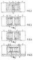
- the live lead 6 (see Fig. 2) is electrically insulated from the heat sink 7 by aluminium nitride 8.
- the live lead 6 is in contact with the neutral lead 5 through the interposed aluminium nitride 8, and the neutral lead in its turn is in contact with the heat sink 7.
- the lamp shown has a luminous efficacy of 100 lm/W at a consumed power of 160 W.
- the lamp vessel 1 is accommodated in a reflector 9 which is closed off by a grid 10 of metal wire.
- the heat sink 7 has fins 11 for an improved heat transfer to the surroundings.
- the two leads 5, 6 together with the aluminium nitride 8 form a capacitance C p which is in parallel to the coil 2 and which together with a capacitance C s connected in series elsewhere adapts the coil and the discharge to their supply unit.
- each of the electric leads 5, 6 has its own heat sink 7, 17, and the live lead 6 is in physical contact with aluminium nitride 8 which is in physical contact with the heat sink 17 of the live lead.
- a capacitance C p is connected in parallel to the discharge and the coil elsewhere.
- the heat sink of the live lead 6 is integral with the heat sink 7 of the neutral lead 5.
- the two electric leads 5, 6 in the embodiment of Fig. 5 are together surrounded by a heat sink 7 which is in contact both with the live lead 6 and with the neutral lead 5 via aluminium nitride 8.
- the heat sink 7 is mounted on a metal support plate 12.
Landscapes
- Physics & Mathematics (AREA)
- Electromagnetism (AREA)
- Engineering & Computer Science (AREA)
- Plasma & Fusion (AREA)
- Discharge Lamps And Accessories Thereof (AREA)
- Arrangement Of Elements, Cooling, Sealing, Or The Like Of Lighting Devices (AREA)
- Circuit Arrangements For Discharge Lamps (AREA)
Claims (5)
- Lampe à décharge à haute pression sans électrodes comportant:un récipient de lampe transmettant la lumière (1) qui est fermé d'une manière étanche au vide et qui présente un remplissage ionisable;autour du récipient de lampe une bobine électrique (2) présentant des parties terminales (3, 4) qui sont reliées électriquement à un conducteur électrique neutre (5) s'éloignant de la bobine (2) respectivement à un conducteur électrique sous tension (6), lesdits conducteurs (5, 6) doivent être reliés à une alimentation électrique,les conducteurs électriques étant reliés à une lame de refroidissement (7),caractérisée en ce que le conducteur électrique sous tension (6) est isolé électriquement de la lame de refroidissement (7) par l'azoture d'aluminium (8).
- Lampe à décharge à haute pression sans électrodes selon la revendication 1, caractérisée en ce que le conducteur sous tension (6) est en contact avec le conducteur neutre (5) par l'interposition d'azoture d'aluminium (8), alors que le conducteur neutre (5) est en contact avec la lame de refroidissement (7).
- Lampe à décharge à haute pression sans électrodes selon la revendication 1, caractérisée en ce que chacun des conducteurs électriques (5, 6) présente sa propre lame de refroidissement (7, 17) et en ce que le conducteur sous tension (6) est en contact avec l'azoture d'aluminium (8) qui est en contact avec la lame de refroidissement (17) du conducteur sous tension (6).
- Lampe à décharge à haute pression sans électrodes selon la revendication 3, caractérisée en ce que la lame de refroidissement (17) du conducteur sous tension (6) fait corps avec la lame de refroidissement (7) du conducteur neutre (5).
- Lampe à décharge à haute pression sans électrodes selon la revendication 1, caractérisée en ce que les deux conducteurs (5, 6) sont entourés conjointement d'une lame de refroidissement (7) qui est en contact avec le conducteur sous tension (6) aussi bien qu'avec le conducteur neutre (5) par l'intermédiaire de l'azoture d'aluminium (8).
Applications Claiming Priority (2)
| Application Number | Priority Date | Filing Date | Title |
|---|---|---|---|
| EP93200428 | 1993-02-16 | ||
| EP93200428 | 1993-02-16 |
Publications (2)
| Publication Number | Publication Date |
|---|---|
| EP0612100A1 EP0612100A1 (fr) | 1994-08-24 |
| EP0612100B1 true EP0612100B1 (fr) | 1996-08-21 |
Family
ID=8213644
Family Applications (1)
| Application Number | Title | Priority Date | Filing Date |
|---|---|---|---|
| EP19940200250 Expired - Lifetime EP0612100B1 (fr) | 1993-02-16 | 1994-02-09 | Lampe à décharge à haute pression sans électrodes |
Country Status (5)
| Country | Link |
|---|---|
| EP (1) | EP0612100B1 (fr) |
| JP (1) | JPH06251884A (fr) |
| CN (1) | CN1095525A (fr) |
| CA (1) | CA2115509A1 (fr) |
| DE (1) | DE69400380T2 (fr) |
Families Citing this family (1)
| Publication number | Priority date | Publication date | Assignee | Title |
|---|---|---|---|---|
| WO1995028734A1 (fr) * | 1994-04-14 | 1995-10-26 | Philips Electronics N.V. | Lampe a decharge sous haute pression sans electrode |
Family Cites Families (3)
| Publication number | Priority date | Publication date | Assignee | Title |
|---|---|---|---|---|
| US5047692A (en) * | 1990-01-30 | 1991-09-10 | General Electric Company | Integrated tuning capacitor network and heat sink for an electrodeless high intensity discharge lamp ballast |
| JP2536657B2 (ja) * | 1990-03-28 | 1996-09-18 | 三菱電機株式会社 | 電気装置及びその製造方法 |
| US5047893A (en) * | 1990-09-24 | 1991-09-10 | General Electric Company | High-frequency capacitor |
-
1994
- 1994-02-09 DE DE1994600380 patent/DE69400380T2/de not_active Expired - Fee Related
- 1994-02-09 EP EP19940200250 patent/EP0612100B1/fr not_active Expired - Lifetime
- 1994-02-11 CA CA 2115509 patent/CA2115509A1/fr not_active Abandoned
- 1994-02-14 CN CN 94100863 patent/CN1095525A/zh active Pending
- 1994-02-14 JP JP1730694A patent/JPH06251884A/ja active Pending
Also Published As
| Publication number | Publication date |
|---|---|
| JPH06251884A (ja) | 1994-09-09 |
| DE69400380D1 (de) | 1996-09-26 |
| CN1095525A (zh) | 1994-11-23 |
| EP0612100A1 (fr) | 1994-08-24 |
| DE69400380T2 (de) | 1997-03-06 |
| CA2115509A1 (fr) | 1994-08-17 |
Similar Documents
| Publication | Publication Date | Title |
|---|---|---|
| EP0612099B1 (fr) | Lampe à décharge à haute pression sans électrodes | |
| US6768248B2 (en) | Electrodeless lamp | |
| TWI239551B (en) | Electrodless discharge lamp | |
| JPH066448Y2 (ja) | 無電極放電ランプ | |
| US6492890B1 (en) | Method and apparatus for cooling transformer coils | |
| EP0198523B1 (fr) | Lampe à décharge basse-pression sans électrode | |
| CA1239436A (fr) | Lampe a decharge sous vapeur haute pression | |
| EP0612100A1 (fr) | Lampe à décharge à haute pression sans électrodes | |
| WO1995028734A1 (fr) | Lampe a decharge sous haute pression sans electrode | |
| CN211607196U (zh) | 一种小型化大功率开关电源 | |
| EP0755570B1 (fr) | Unite d'eclairage, lampe a decharge basse pression sans electrode et enceinte de decharge | |
| JP3707312B2 (ja) | 高圧トランス装置 | |
| CN212366826U (zh) | 保护器件 | |
| CN223052619U (zh) | 一种气体绝缘封闭开关设备 | |
| CN1316553C (zh) | 高压放电灯 | |
| JPH0629084A (ja) | 高周波加熱装置 | |
| CN118648386A (zh) | 电气系统和电气驱动单元 | |
| JP3418191B2 (ja) | 無電極放電ランプ | |
| JP2571557Y2 (ja) | 無電極放電灯装置 | |
| CA2300741A1 (fr) | Lampe a decharge a haute pression | |
| JP2004039330A (ja) | 無電極放電ランプ | |
| JPS59209261A (ja) | ガス放電管 |
Legal Events
| Date | Code | Title | Description |
|---|---|---|---|
| PUAI | Public reference made under article 153(3) epc to a published international application that has entered the european phase |
Free format text: ORIGINAL CODE: 0009012 |
|
| AK | Designated contracting states |
Kind code of ref document: A1 Designated state(s): BE DE ES FR GB IT NL |
|
| 17P | Request for examination filed |
Effective date: 19950224 |
|
| 17Q | First examination report despatched |
Effective date: 19950912 |
|
| GRAH | Despatch of communication of intention to grant a patent |
Free format text: ORIGINAL CODE: EPIDOS IGRA |
|
| GRAH | Despatch of communication of intention to grant a patent |
Free format text: ORIGINAL CODE: EPIDOS IGRA |
|
| GRAA | (expected) grant |
Free format text: ORIGINAL CODE: 0009210 |
|
| AK | Designated contracting states |
Kind code of ref document: B1 Designated state(s): BE DE ES FR GB IT NL |
|
| PG25 | Lapsed in a contracting state [announced via postgrant information from national office to epo] |
Ref country code: NL Free format text: LAPSE BECAUSE OF FAILURE TO SUBMIT A TRANSLATION OF THE DESCRIPTION OR TO PAY THE FEE WITHIN THE PRESCRIBED TIME-LIMIT Effective date: 19960821 Ref country code: IT Free format text: LAPSE BECAUSE OF FAILURE TO SUBMIT A TRANSLATION OF THE DESCRIPTION OR TO PAY THE FEE WITHIN THE PRESCRIBED TIME-LIMIT;WARNING: LAPSES OF ITALIAN PATENTS WITH EFFECTIVE DATE BEFORE 2007 MAY HAVE OCCURRED AT ANY TIME BEFORE 2007. THE CORRECT EFFECTIVE DATE MAY BE DIFFERENT FROM THE ONE RECORDED. Effective date: 19960821 Ref country code: ES Free format text: THE PATENT HAS BEEN ANNULLED BY A DECISION OF A NATIONAL AUTHORITY Effective date: 19960821 Ref country code: BE Effective date: 19960821 |
|
| REF | Corresponds to: |
Ref document number: 69400380 Country of ref document: DE Date of ref document: 19960926 |
|
| ET | Fr: translation filed | ||
| ET | Fr: translation filed | ||
| NLV1 | Nl: lapsed or annulled due to failure to fulfill the requirements of art. 29p and 29m of the patents act | ||
| PLBE | No opposition filed within time limit |
Free format text: ORIGINAL CODE: 0009261 |
|
| STAA | Information on the status of an ep patent application or granted ep patent |
Free format text: STATUS: NO OPPOSITION FILED WITHIN TIME LIMIT |
|
| 26N | No opposition filed | ||
| REG | Reference to a national code |
Ref country code: FR Ref legal event code: CD |
|
| PGFP | Annual fee paid to national office [announced via postgrant information from national office to epo] |
Ref country code: FR Payment date: 20000222 Year of fee payment: 7 |
|
| PGFP | Annual fee paid to national office [announced via postgrant information from national office to epo] |
Ref country code: GB Payment date: 20000228 Year of fee payment: 7 |
|
| PGFP | Annual fee paid to national office [announced via postgrant information from national office to epo] |
Ref country code: DE Payment date: 20000419 Year of fee payment: 7 |
|
| PG25 | Lapsed in a contracting state [announced via postgrant information from national office to epo] |
Ref country code: GB Free format text: LAPSE BECAUSE OF NON-PAYMENT OF DUE FEES Effective date: 20010209 |
|
| GBPC | Gb: european patent ceased through non-payment of renewal fee |
Effective date: 20010209 |
|
| PG25 | Lapsed in a contracting state [announced via postgrant information from national office to epo] |
Ref country code: FR Free format text: LAPSE BECAUSE OF NON-PAYMENT OF DUE FEES Effective date: 20011031 |
|
| REG | Reference to a national code |
Ref country code: FR Ref legal event code: ST |
|
| PG25 | Lapsed in a contracting state [announced via postgrant information from national office to epo] |
Ref country code: DE Free format text: LAPSE BECAUSE OF NON-PAYMENT OF DUE FEES Effective date: 20011201 |