EP0612175A2 - Leitungskodierung für Verteiltkanalübertragung - Google Patents
Leitungskodierung für Verteiltkanalübertragung Download PDFInfo
- Publication number
- EP0612175A2 EP0612175A2 EP94300492A EP94300492A EP0612175A2 EP 0612175 A2 EP0612175 A2 EP 0612175A2 EP 94300492 A EP94300492 A EP 94300492A EP 94300492 A EP94300492 A EP 94300492A EP 0612175 A2 EP0612175 A2 EP 0612175A2
- Authority
- EP
- European Patent Office
- Prior art keywords
- data
- weight
- value
- group
- code
- Prior art date
- Legal status (The legal status is an assumption and is not a legal conclusion. Google has not performed a legal analysis and makes no representation as to the accuracy of the status listed.)
- Withdrawn
Links
- 230000005540 biological transmission Effects 0.000 title description 9
- 238000000034 method Methods 0.000 claims description 41
- 238000004891 communication Methods 0.000 claims description 9
- 238000001514 detection method Methods 0.000 abstract description 7
- 125000004122 cyclic group Chemical group 0.000 abstract description 5
- 230000009977 dual effect Effects 0.000 abstract 1
- 239000004020 conductor Substances 0.000 description 41
- 238000006467 substitution reaction Methods 0.000 description 6
- 238000012360 testing method Methods 0.000 description 6
- 238000005516 engineering process Methods 0.000 description 5
- 238000010586 diagram Methods 0.000 description 3
- 229910002056 binary alloy Inorganic materials 0.000 description 2
- 230000001186 cumulative effect Effects 0.000 description 2
- 238000013500 data storage Methods 0.000 description 2
- 238000011161 development Methods 0.000 description 2
- 230000018109 developmental process Effects 0.000 description 2
- 230000003287 optical effect Effects 0.000 description 2
- 239000000835 fiber Substances 0.000 description 1
- 238000009434 installation Methods 0.000 description 1
- 230000007774 longterm Effects 0.000 description 1
- 230000006855 networking Effects 0.000 description 1
- 239000013307 optical fiber Substances 0.000 description 1
- 238000012545 processing Methods 0.000 description 1
- 230000011664 signaling Effects 0.000 description 1
Images



Classifications
-
- H—ELECTRICITY
- H04—ELECTRIC COMMUNICATION TECHNIQUE
- H04L—TRANSMISSION OF DIGITAL INFORMATION, e.g. TELEGRAPHIC COMMUNICATION
- H04L1/00—Arrangements for detecting or preventing errors in the information received
- H04L1/22—Arrangements for detecting or preventing errors in the information received using redundant apparatus to increase reliability
-
- H—ELECTRICITY
- H04—ELECTRIC COMMUNICATION TECHNIQUE
- H04L—TRANSMISSION OF DIGITAL INFORMATION, e.g. TELEGRAPHIC COMMUNICATION
- H04L25/00—Baseband systems
- H04L25/02—Details ; arrangements for supplying electrical power along data transmission lines
- H04L25/14—Channel dividing arrangements, i.e. in which a single bit stream is divided between several baseband channels and reassembled at the receiver
-
- H—ELECTRICITY
- H04—ELECTRIC COMMUNICATION TECHNIQUE
- H04L—TRANSMISSION OF DIGITAL INFORMATION, e.g. TELEGRAPHIC COMMUNICATION
- H04L25/00—Baseband systems
- H04L25/38—Synchronous or start-stop systems, e.g. for Baudot code
- H04L25/40—Transmitting circuits; Receiving circuits
- H04L25/49—Transmitting circuits; Receiving circuits using code conversion at the transmitter; using predistortion; using insertion of idle bits for obtaining a desired frequency spectrum; using three or more amplitude levels ; Baseband coding techniques specific to data transmission systems
- H04L25/4906—Transmitting circuits; Receiving circuits using code conversion at the transmitter; using predistortion; using insertion of idle bits for obtaining a desired frequency spectrum; using three or more amplitude levels ; Baseband coding techniques specific to data transmission systems using binary codes
- H04L25/4908—Transmitting circuits; Receiving circuits using code conversion at the transmitter; using predistortion; using insertion of idle bits for obtaining a desired frequency spectrum; using three or more amplitude levels ; Baseband coding techniques specific to data transmission systems using binary codes using mBnB codes
Definitions
- This invention relates to methods and systems for communicating data, and particularly, though not exclusively, to methods and systems for communicating data over a plurality of channels, such as a cable having a plurality of conductors (for example a four-wire telephone cable).
- a plurality of channels such as a cable having a plurality of conductors (for example a four-wire telephone cable).
- FDDI fibre distributed data interface
- UTP unshielded twisted-pair
- a method for communicating encoded data over a channel using a code having two groups of data values, each data value in a first group having one or more code words all of weight n (weight being calculated as described below), and each data value in a second group having a plurality of code words each of which is of weight n + x (e.g. n -1) or n + y (e.g.
- Digital data is commonly communicated physically by transmitting different respective voltages for different digital values.
- +2.5 volts may represent a binary 1 and -2.5 volts may represent a binary 0; in a ternary (three-level) system +2.5 volts may represent a ternary 1, 0 volts may represent a ternary 0, and -2.5 volts may represent a ternary -1.
- d.c. balance i.e. to avoid any long-term departure of cumulative signal voltage from an equilibrium value. This may be accomplished by the use of a code in which the cumulative weight (as described below) of the code words does not depart from some predetermined value by more than some predetermined limit.
- the term 'weight' refers to the relative numbers of differently valued symbols in a code word.
- the weight may refer to the number of binary 1's in a code word relative to some reference quantity.
- a code word 111000 may be considered to have a weight (expressed as number of 1's above or below three) of 0, a code word 001100 to have a weight of -1 and a code word 110011 to have a weight of +1.
- the weight may be expressed, for example, as the sum of the symbol values in a code word, the three possible symbol values being -1,0 and +1.
- apparatus for communicating encoded data over a channel using a code having two groups of data values, each data value in a first group having one or more code words all of weight n, and each data value in a second group having a plurality of code words each of which is of weight n + x or n + y and having at least one code word of each weight, comprising: means for encoding data values in said first group; means for selecting code words of weight n + x and n + y alternately upon each occurrence of any data value in said second group; and means for terminating communication of data over said channel with a delimiter selected from at least two predetermined delimiters in accordance with the weight which would be selected for a code word corresponding to a data value in said second group and occurring in place of said delimiter.
- the present invention may be used, for example, in circumstances where a stream of data is communicated over a plurality of channels, successive portions of the data stream being communicated simultaneously over different respective channels in order to obtain a higher bandwidth than would be possible if all the data were transmitted over a single such channel.
- the invention will be described in the context of transmission of binary data over a cable having four channels or conductors (e.g. four pairs of twisted wires).
- the invention is not limited to this particular number of channels nor to this type of channel nor to binary data.
- the cable would, for example, form part of a network connecting many stations or nodes, such as personal computers, workstations, multi-user computers, printers or data storage units.
- Circuit devices associated with these stations would provide the necessary functions for assembling data and network operating information into frames or packets for transmission, for controlling access to the network and for transmitting and receiving physical signals on the cable (for example by differential signalling in the case of twisted-pair conductors).
- the present invention is independent of the particular details of these functions and may for example be implemented in conjunction with existing network technologies; since such technologies already incorporate known techniques for providing these functions, and the functions form no part of the present invention, they will not be described here.
- a data frame intended to be communicated over a four-conductor cable is shown schematically at 10.
- CRC cyclic redundancy check
- the data frame For transmission over the four-conductor cable the data frame is split into consecutive blocks of five bits each, and the blocks are distributed among the four conductors (herein labelled A to D) on a cyclic basis and starting with the block containing the leftmost bit of the data frame.
- the first block labelled Al in Figure 1
- the next block B1 via conductor B
- the third block C1 via conductor C
- the fourth (D1) via conductor D.
- the cycle then repeats, with conductor A being used again, for the fifth block (A2), and so on.
- the five-bit data blocks Prior to transmission the five-bit data blocks are encoded by a 5-to-6 bit encoder 16 ( Figure 2) into six-bit values according to a substitution table, to provide a measure of inherent error detection.
- the encoding substitutions may be as shown in Figure 3. These particular substitutions are selected in part to maintain d.c. balance on each conductor, by ensuring that after transmission of each coded data block the accumulated weight, as described above, is always in the range -1 to +1.
- the encoding is implemented so that on the first occasion in a frame that one of the second group of twelve data blocks occurs for transmission along a particular conductor, the corresponding two-ones encoding is selected (left-hand column); on the next occasion that any of these twelve data blocks occurs for transmission along that same conductor, the corresponding four-ones encoding is used (right-hand column); thereafter the use of the two-ones and four-ones encodings continues to alternate for each occurrence of any of the second group of data blocks in respect of that conductor.
- the numbers of two-ones and four-ones six-bit codes will differ at most by one, maintaining an average of three binary zeroes (zero weight) per six-bit code and providing the desired d.c. balance.
- Figure 1 illustrative five-bit data blocks are indicated in bold characters, and corresponding six-bit code values are indicated below them in normal characters.
- the six-bit code values are distributed or 'de-multiplexed' by a de-multiplexer 18 among the four conductors A to D on a cyclic basis as described above.
- conductor A will carry encoded data blocks A1, A2, A3, etc. in succession (leftmost bit of each first)
- conductor B will carry encoded data blocks B1, B2, B3, etc., and likewise for conductors C and D.
- data blocks are transmitted on conductors A and B coincidentally (or, in terms of overall blocks, in phase with each other), and offset from (or out of phase with) the data blocks transmitted coincidentally with one another on conductors C and D.
- a twelve-bit end delimiter is transmitted on each conductor.
- This delimiter has two possible values: one value, identified as DL2 in Figure 2, has the binary value 111111000000; the other value, identified as DL4, has the binary value 000000111111.
- the particular values indicated are purely exemplary - they are chosen to be readily distinguishable from encoded data blocks, and values which maintain d.c. balance are preferred.
- the choice between these values for each conductor is determined by the weight of the code word most recently transmitted on that conductor for any one of the second group of twelve data values having two possible code values.
- the DL4 delimiter is chosen; otherwise (or if no data value from the second group occurs during the frame on that conductor) the DL2 delimiter is used. (In the example shown in Figure 2, it is assumed that no further data values from the second group occur after data value B3.)
- a multiplexer 20 At the receiving end of the conductors A to D, a multiplexer 20 'multiplexes' the four signals to reconstruct the original encoded data stream, after compensating for the offset between the the signals on conductors C and D and those on conductors A and B.
- a decoder 22 then converts each six-bit encoded block to derive the corresponding five-bit data block, and checks the CRC value. If the CRC value is invalid, or any six-bit encoded value is encountered which is invalid, or there is a violation for any conductor of the alternating pattern of encodings of weight + 1 and -1 for data values in the second group, the decoder 22 rejects the entire data frame. Any departure from this alternating pattern, in encoded data values or in the end delimiter, indicates that at least one error has occurred.
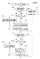
- Figure 4 shows a flow diagram of a method for implementing the encoding and choice of end delimiter. This procedure uses four boolean flags, one for each conductor, which are set to 'true' at the start of each frame.
- the purpose of this counter is to keep track of which conductor the current (encoded) data value will be transmitted along.
- the data value to be encoded is tested to check whether it has one or two corresponding six-bit code values. If there is a unique corresponding code value, the procedure obtains that value from a look-up table at step 104 and advances to step 114, described below. Otherwise the procedure advances to step 106, where one of the above-mentioned boolean flags, selected in accordance with the current value of the counter K, is tested.
- the procedure selects the code value containing only two binary ones, at step 108; if the flag is 'false' the code value containing four ones is selected, at step 110. In either case the procedure then inverts the value of the flag at step 112.
- the procedure tests whether the current frame is full (i.e. the prescribed maximum size for a frame has been attained) and whether a data buffer from which data is taken for encoding is empty. If neither of these circumstances applies, the procedure exits for transmission of the encoded data block. If either test is satisfied, the current frame is completed and an end delimiter must be selected. Accordingly, at step 116, the relevant one of the above-mentioned four boolean flags, selected in accordance with the current value of the counter K, is tested.
- the procedure selects the DL2 delimiter (111111000000), at step 118; if the flag is 'false' the DL4 delimiter (000000111111) is selected, at step 120. In either case the procedure then resets the value of the flag at step 122 to 'true' in preparation for the following frame.
- Figure 5 shows a procedure, similar to that of Figure 4, for use in the decoder 22 to track the alternating pattern of encodings of weight +1 and -1, and verify that the pattern has been correctly maintained in the received data stream.
- this procedure uses four boolean flags, one for each conductor, which are set to 'true' at the start of each frame.
- a counter L is incremented in a similar manner to the counter K in Figure 4, to keep track of which conductor the current (encoded) data value was transmitted along.
- the next step, 201 tests whether the current code value is the start of an end delimiter (111111 or 000000). If so, the procedure advances to step 216, described below. Otherwise, at step 202 the code value is tested to check whether it contains three binary 1's. If it does, the procedure obtains the corresponding data value from the look-up table at step 204. Otherwise the procedure advances to step 206, where one of the above-mentioned boolean flags, selected in accordance with the current value of the counter L, is tested.
- step 208 the code value is tested to check whether it contains only two binary ones; if the flag is 'false' the code value is tested to check if it contains four ones, at step 210. If the selected test fails, the procedure indicates an error, at step 224. Otherwise the procedure inverts the value of the flag, at step 212, and then decodes the code value at step 204.
- the relevant one of the four boolean flags selected in accordance with the current value of the counter L, is tested at step 216. If the flag is 'true', the procedure tests whether the end delimiter has the DL2 value (111111000000), at step 218; if the flag is 'false' the delimiter is tested for the DL4 value (000000111111), at step 220. If the relevant test fails, the procedure indicates an error at step 224. Otherwise the value of the flag is reset at step 222 to 'true' in preparation for the following frame.
Landscapes
- Engineering & Computer Science (AREA)
- Computer Networks & Wireless Communication (AREA)
- Signal Processing (AREA)
- Physics & Mathematics (AREA)
- Spectroscopy & Molecular Physics (AREA)
- Power Engineering (AREA)
- Detection And Prevention Of Errors In Transmission (AREA)
- Dc Digital Transmission (AREA)
Applications Claiming Priority (2)
| Application Number | Priority Date | Filing Date | Title |
|---|---|---|---|
| US20038 | 1987-02-27 | ||
| US08/020,038 US5396503A (en) | 1993-02-19 | 1993-02-19 | Method and system for communicating data |
Publications (2)
| Publication Number | Publication Date |
|---|---|
| EP0612175A2 true EP0612175A2 (de) | 1994-08-24 |
| EP0612175A3 EP0612175A3 (en) | 1996-01-10 |
Family
ID=21796398
Family Applications (1)
| Application Number | Title | Priority Date | Filing Date |
|---|---|---|---|
| EP94300492A Withdrawn EP0612175A3 (en) | 1993-02-19 | 1994-01-24 | Line coding for split channel transmission. |
Country Status (3)
| Country | Link |
|---|---|
| US (1) | US5396503A (de) |
| EP (1) | EP0612175A3 (de) |
| JP (1) | JPH0730521A (de) |
Cited By (5)
| Publication number | Priority date | Publication date | Assignee | Title |
|---|---|---|---|---|
| US5664108A (en) * | 1993-09-23 | 1997-09-02 | Standard Microsystems Corporation | High bit rate CSMA/CD using multiple pairs |
| EP0876021A1 (de) * | 1997-04-30 | 1998-11-04 | Hewlett-Packard Company | Anordnung und Verfahren zur Übertragung von Daten über eine Vielzahl von Kanälen |
| GB2380101A (en) * | 2001-08-30 | 2003-03-26 | Daewoo Electronics Co Ltd | Block encoding and decoding method |
| WO2003028241A3 (en) * | 2001-09-26 | 2004-03-04 | Intel Corp | Crosstalk equalization for digital transmission lines |
| CN100446513C (zh) * | 2001-08-02 | 2008-12-24 | E-3解决方案有限公司 | 由作为中继服务器的终端分配数据包的网络和方法 |
Families Citing this family (4)
| Publication number | Priority date | Publication date | Assignee | Title |
|---|---|---|---|---|
| US5491688A (en) * | 1994-07-05 | 1996-02-13 | Bocci; Paul | Method for providing a favorable signal representation |
| US5640605A (en) * | 1994-08-26 | 1997-06-17 | 3Com Corporation | Method and apparatus for synchronized transmission of data between a network adaptor and multiple transmission channels using a shared clocking frequency and multilevel data encoding |
| US5719871A (en) * | 1995-04-19 | 1998-02-17 | Motorola, Inc. | Method and apparatus for performing diversity voting in a communication system |
| DE69829960D1 (de) * | 1998-07-07 | 2005-06-02 | Agilent Technologies Inc | Blockkode mit begrenzter Disparität |
Family Cites Families (17)
| Publication number | Priority date | Publication date | Assignee | Title |
|---|---|---|---|---|
| GB1250908A (de) * | 1968-12-13 | 1971-10-27 | ||
| GB1540617A (en) * | 1968-12-13 | 1979-02-14 | Post Office | Transformation of binary coded signals into a form having lower disparity |
| NL170688C (nl) * | 1976-06-28 | 1982-12-01 | Philips Nv | Inrichting voor simultane tweerichtingsdatatransmissie over tweedraadsverbindingen. |
| GB1592556A (en) * | 1976-10-28 | 1981-07-08 | Rixon | Quadrature-amplitude-modulation data transmission systems and transmitters |
| US4270203A (en) * | 1978-11-13 | 1981-05-26 | Arthur A. Collins, Inc. | Timing adjustment circuit for digital switching |
| JPS5665313A (en) * | 1979-10-29 | 1981-06-03 | Sony Corp | Data converting circuit |
| US4383316A (en) * | 1980-04-14 | 1983-05-10 | Bell Telephone Laboratories, Incorporated | Apparatus for and method of collating partitioned time disordered synchronous data streams |
| US4611326A (en) * | 1983-03-28 | 1986-09-09 | Digital Equipment Corporation | Circuitry for identifying the validity of received data words |
| GB8407223D0 (en) * | 1984-03-20 | 1984-04-26 | British Telecomm | Broadband digital transmission systems |
| US4594707A (en) * | 1984-09-17 | 1986-06-10 | Motorola, Inc. | High speed limited distance multiplexed data communications modem using a single twisted pair of conductors |
| US4675863A (en) * | 1985-03-20 | 1987-06-23 | International Mobile Machines Corp. | Subscriber RF telephone system for providing multiple speech and/or data signals simultaneously over either a single or a plurality of RF channels |
| US4805194A (en) * | 1985-10-17 | 1989-02-14 | Ampex Corporation | Serial data communication system |
| JPH07105818B2 (ja) * | 1986-05-19 | 1995-11-13 | 株式会社日立製作所 | 並列伝送方式 |
| US4980897A (en) * | 1988-08-12 | 1990-12-25 | Telebit Corporation | Multi-channel trellis encoder/decoder |
| US4933930A (en) * | 1988-10-31 | 1990-06-12 | International Business Machines Corporation | High speed switch as for an optical communication system |
| US5255287A (en) * | 1991-06-28 | 1993-10-19 | Digital Equipment Corporation | Transceiver apparatus and methods |
| GB9314479D0 (en) * | 1992-11-06 | 1993-08-25 | Hewlett Packard Co | Encoding data |
-
1993
- 1993-02-19 US US08/020,038 patent/US5396503A/en not_active Expired - Fee Related
-
1994
- 1994-01-24 EP EP94300492A patent/EP0612175A3/en not_active Withdrawn
- 1994-02-18 JP JP6045229A patent/JPH0730521A/ja active Pending
Cited By (10)
| Publication number | Priority date | Publication date | Assignee | Title |
|---|---|---|---|---|
| US5664108A (en) * | 1993-09-23 | 1997-09-02 | Standard Microsystems Corporation | High bit rate CSMA/CD using multiple pairs |
| EP0876021A1 (de) * | 1997-04-30 | 1998-11-04 | Hewlett-Packard Company | Anordnung und Verfahren zur Übertragung von Daten über eine Vielzahl von Kanälen |
| US6119263A (en) * | 1997-04-30 | 2000-09-12 | Hewlett-Packard Company | System and method for transmitting data |
| CN100446513C (zh) * | 2001-08-02 | 2008-12-24 | E-3解决方案有限公司 | 由作为中继服务器的终端分配数据包的网络和方法 |
| GB2380101A (en) * | 2001-08-30 | 2003-03-26 | Daewoo Electronics Co Ltd | Block encoding and decoding method |
| GB2380101B (en) * | 2001-08-30 | 2004-11-10 | Daewoo Electronics Co Ltd | Block coding/decoding method & apparatus for increasing code rate |
| US6954554B2 (en) | 2001-08-30 | 2005-10-11 | Daewoo Electronics Corporation | Block coding/decoding method and apparatus for increasing code rate |
| WO2003028241A3 (en) * | 2001-09-26 | 2004-03-04 | Intel Corp | Crosstalk equalization for digital transmission lines |
| US6920183B2 (en) | 2001-09-26 | 2005-07-19 | Intel Corporation | Crosstalk equalization for input-output driver circuits |
| CN100421436C (zh) * | 2001-09-26 | 2008-09-24 | 英特尔公司 | 输入-输出驱动器电路的串扰均衡 |
Also Published As
| Publication number | Publication date |
|---|---|
| JPH0730521A (ja) | 1995-01-31 |
| EP0612175A3 (en) | 1996-01-10 |
| US5396503A (en) | 1995-03-07 |
Similar Documents
| Publication | Publication Date | Title |
|---|---|---|
| EP0824817B1 (de) | Vorrichtung und verfahren zur datenübertragung von datenwortblöcken zusammen mit kontrollwörtern | |
| US6978416B2 (en) | Error correction with low latency for bus structures | |
| EP0731586B1 (de) | Gleichtaktfreier ternärer Kode | |
| US7055073B2 (en) | Coding method for coding packetized serial data with low overhead | |
| CN100353690C (zh) | 使用普通网络分组发送多个8b/10b位流的多路传输系统 | |
| US7440513B2 (en) | Coding and decoding packetized data | |
| EP0491868B1 (de) | Fehlererkennung für verteilte über schnittstelle anschliessende glasfaserverbindung | |
| EP1133123A2 (de) | 64b/66b-Dekodierung, für in Paketen geordnete, serielle Daten | |
| EP0886407B1 (de) | 5B6B-Kodierung für Verteiltkanalübertragung | |
| EP0735729B1 (de) | 5B4T-Kodierungsschema | |
| US5396503A (en) | Method and system for communicating data | |
| EP0735728B1 (de) | 5B4T Kodierungsschema | |
| EP1450529A2 (de) | Erweiterter Steuerzeichensatz für mehrspurige Kommunikation | |
| US5612694A (en) | Encoding data | |
| EP0430052B1 (de) | Codezeichen zum Übertragen von Daten von einem Netzwerkübertragungsmedium zu einer Station auf dem Netzwerk | |
| US6088369A (en) | Line coding technique for efficient transmission and delineation of encapsulated frames over high speed data links | |
| JPH0681166B2 (ja) | デイジタル伝送装置 | |
| EP0240146B1 (de) | Verfahren und Gerät zur Serienübertragung auf einen Kanal von redundanten, codierten, binären Daten | |
| US7302631B2 (en) | Low overhead coding techniques | |
| Crouch et al. | Coding in 100VG-AnyLAN |
Legal Events
| Date | Code | Title | Description |
|---|---|---|---|
| PUAI | Public reference made under article 153(3) epc to a published international application that has entered the european phase |
Free format text: ORIGINAL CODE: 0009012 |
|
| AK | Designated contracting states |
Kind code of ref document: A2 Designated state(s): DE FR GB IT SE |
|
| PUAL | Search report despatched |
Free format text: ORIGINAL CODE: 0009013 |
|
| AK | Designated contracting states |
Kind code of ref document: A3 Designated state(s): DE FR GB IT SE |
|
| 17P | Request for examination filed |
Effective date: 19960704 |
|
| STAA | Information on the status of an ep patent application or granted ep patent |
Free format text: STATUS: THE APPLICATION HAS BEEN WITHDRAWN |
|
| 18W | Application withdrawn |
Withdrawal date: 19981030 |