EP0612509B1 - Einstellbares Prothesenpfannenteil für anatomische Gelenke - Google Patents
Einstellbares Prothesenpfannenteil für anatomische Gelenke Download PDFInfo
- Publication number
- EP0612509B1 EP0612509B1 EP94200433A EP94200433A EP0612509B1 EP 0612509 B1 EP0612509 B1 EP 0612509B1 EP 94200433 A EP94200433 A EP 94200433A EP 94200433 A EP94200433 A EP 94200433A EP 0612509 B1 EP0612509 B1 EP 0612509B1
- Authority
- EP
- European Patent Office
- Prior art keywords
- liner
- plane
- shell member
- cavity
- recited
- Prior art date
- Legal status (The legal status is an assumption and is not a legal conclusion. Google has not performed a legal analysis and makes no representation as to the accuracy of the status listed.)
- Expired - Lifetime
Links
- 230000007935 neutral effect Effects 0.000 claims description 32
- 210000000988 bone and bone Anatomy 0.000 claims description 24
- 210000000588 acetabulum Anatomy 0.000 claims description 10
- 210000000689 upper leg Anatomy 0.000 claims description 10
- 238000003780 insertion Methods 0.000 claims description 4
- 230000037431 insertion Effects 0.000 claims description 4
- 230000000295 complement effect Effects 0.000 claims description 3
- 230000004044 response Effects 0.000 claims description 2
- 230000001154 acute effect Effects 0.000 claims 2
- 238000001356 surgical procedure Methods 0.000 description 21
- 210000001503 joint Anatomy 0.000 description 11
- 230000008859 change Effects 0.000 description 9
- 238000000034 method Methods 0.000 description 9
- 239000000463 material Substances 0.000 description 5
- 230000007246 mechanism Effects 0.000 description 5
- 230000008569 process Effects 0.000 description 5
- 230000008901 benefit Effects 0.000 description 4
- 210000001624 hip Anatomy 0.000 description 4
- 210000004394 hip joint Anatomy 0.000 description 4
- 238000002513 implantation Methods 0.000 description 4
- 229910000684 Cobalt-chrome Inorganic materials 0.000 description 2
- 206010023204 Joint dislocation Diseases 0.000 description 2
- 238000011882 arthroplasty Methods 0.000 description 2
- 239000011324 bead Substances 0.000 description 2
- 230000001419 dependent effect Effects 0.000 description 2
- 230000001788 irregular Effects 0.000 description 2
- 210000002414 leg Anatomy 0.000 description 2
- 229910052751 metal Inorganic materials 0.000 description 2
- 239000002184 metal Substances 0.000 description 2
- 150000002739 metals Chemical class 0.000 description 2
- -1 polyethylene Polymers 0.000 description 2
- 210000001694 thigh bone Anatomy 0.000 description 2
- 239000004698 Polyethylene Substances 0.000 description 1
- RTAQQCXQSZGOHL-UHFFFAOYSA-N Titanium Chemical compound [Ti] RTAQQCXQSZGOHL-UHFFFAOYSA-N 0.000 description 1
- 208000027418 Wounds and injury Diseases 0.000 description 1
- 239000010952 cobalt-chrome Substances 0.000 description 1
- 238000007796 conventional method Methods 0.000 description 1
- 230000008878 coupling Effects 0.000 description 1
- 238000010168 coupling process Methods 0.000 description 1
- 238000005859 coupling reaction Methods 0.000 description 1
- 230000006378 damage Effects 0.000 description 1
- 230000002950 deficient Effects 0.000 description 1
- 238000013461 design Methods 0.000 description 1
- 201000010099 disease Diseases 0.000 description 1
- 208000037265 diseases, disorders, signs and symptoms Diseases 0.000 description 1
- 238000011540 hip replacement Methods 0.000 description 1
- 239000007943 implant Substances 0.000 description 1
- 208000014674 injury Diseases 0.000 description 1
- 238000004519 manufacturing process Methods 0.000 description 1
- 238000012986 modification Methods 0.000 description 1
- 230000004048 modification Effects 0.000 description 1
- 210000004197 pelvis Anatomy 0.000 description 1
- 229920003023 plastic Polymers 0.000 description 1
- 239000004033 plastic Substances 0.000 description 1
- 229920000573 polyethylene Polymers 0.000 description 1
- 210000001519 tissue Anatomy 0.000 description 1
- 239000010936 titanium Substances 0.000 description 1
- 229910052719 titanium Inorganic materials 0.000 description 1
- 230000007704 transition Effects 0.000 description 1
- 230000000007 visual effect Effects 0.000 description 1
- 238000012800 visualization Methods 0.000 description 1
Images


Classifications
-
- A—HUMAN NECESSITIES
- A61—MEDICAL OR VETERINARY SCIENCE; HYGIENE
- A61F—FILTERS IMPLANTABLE INTO BLOOD VESSELS; PROSTHESES; DEVICES PROVIDING PATENCY TO, OR PREVENTING COLLAPSING OF, TUBULAR STRUCTURES OF THE BODY, e.g. STENTS; ORTHOPAEDIC, NURSING OR CONTRACEPTIVE DEVICES; FOMENTATION; TREATMENT OR PROTECTION OF EYES OR EARS; BANDAGES, DRESSINGS OR ABSORBENT PADS; FIRST-AID KITS
- A61F2/00—Filters implantable into blood vessels; Prostheses, i.e. artificial substitutes or replacements for parts of the body; Appliances for connecting them with the body; Devices providing patency to, or preventing collapsing of, tubular structures of the body, e.g. stents
- A61F2/02—Prostheses implantable into the body
- A61F2/30—Joints
- A61F2/32—Joints for the hip
- A61F2/34—Acetabular cups
-
- A—HUMAN NECESSITIES
- A61—MEDICAL OR VETERINARY SCIENCE; HYGIENE
- A61F—FILTERS IMPLANTABLE INTO BLOOD VESSELS; PROSTHESES; DEVICES PROVIDING PATENCY TO, OR PREVENTING COLLAPSING OF, TUBULAR STRUCTURES OF THE BODY, e.g. STENTS; ORTHOPAEDIC, NURSING OR CONTRACEPTIVE DEVICES; FOMENTATION; TREATMENT OR PROTECTION OF EYES OR EARS; BANDAGES, DRESSINGS OR ABSORBENT PADS; FIRST-AID KITS
- A61F2/00—Filters implantable into blood vessels; Prostheses, i.e. artificial substitutes or replacements for parts of the body; Appliances for connecting them with the body; Devices providing patency to, or preventing collapsing of, tubular structures of the body, e.g. stents
- A61F2/02—Prostheses implantable into the body
- A61F2/30—Joints
- A61F2/46—Special tools for implanting artificial joints
- A61F2/4603—Special tools for implanting artificial joints for insertion or extraction of endoprosthetic joints or of accessories thereof
- A61F2/4609—Special tools for implanting artificial joints for insertion or extraction of endoprosthetic joints or of accessories thereof of acetabular cups
-
- A—HUMAN NECESSITIES
- A61—MEDICAL OR VETERINARY SCIENCE; HYGIENE
- A61F—FILTERS IMPLANTABLE INTO BLOOD VESSELS; PROSTHESES; DEVICES PROVIDING PATENCY TO, OR PREVENTING COLLAPSING OF, TUBULAR STRUCTURES OF THE BODY, e.g. STENTS; ORTHOPAEDIC, NURSING OR CONTRACEPTIVE DEVICES; FOMENTATION; TREATMENT OR PROTECTION OF EYES OR EARS; BANDAGES, DRESSINGS OR ABSORBENT PADS; FIRST-AID KITS
- A61F2/00—Filters implantable into blood vessels; Prostheses, i.e. artificial substitutes or replacements for parts of the body; Appliances for connecting them with the body; Devices providing patency to, or preventing collapsing of, tubular structures of the body, e.g. stents
- A61F2/02—Prostheses implantable into the body
- A61F2/30—Joints
- A61F2/46—Special tools for implanting artificial joints
- A61F2/4684—Trial or dummy prostheses
-
- A—HUMAN NECESSITIES
- A61—MEDICAL OR VETERINARY SCIENCE; HYGIENE
- A61F—FILTERS IMPLANTABLE INTO BLOOD VESSELS; PROSTHESES; DEVICES PROVIDING PATENCY TO, OR PREVENTING COLLAPSING OF, TUBULAR STRUCTURES OF THE BODY, e.g. STENTS; ORTHOPAEDIC, NURSING OR CONTRACEPTIVE DEVICES; FOMENTATION; TREATMENT OR PROTECTION OF EYES OR EARS; BANDAGES, DRESSINGS OR ABSORBENT PADS; FIRST-AID KITS
- A61F2/00—Filters implantable into blood vessels; Prostheses, i.e. artificial substitutes or replacements for parts of the body; Appliances for connecting them with the body; Devices providing patency to, or preventing collapsing of, tubular structures of the body, e.g. stents
- A61F2/02—Prostheses implantable into the body
- A61F2/30—Joints
- A61F2/30767—Special external or bone-contacting surface, e.g. coating for improving bone ingrowth
-
- A—HUMAN NECESSITIES
- A61—MEDICAL OR VETERINARY SCIENCE; HYGIENE
- A61F—FILTERS IMPLANTABLE INTO BLOOD VESSELS; PROSTHESES; DEVICES PROVIDING PATENCY TO, OR PREVENTING COLLAPSING OF, TUBULAR STRUCTURES OF THE BODY, e.g. STENTS; ORTHOPAEDIC, NURSING OR CONTRACEPTIVE DEVICES; FOMENTATION; TREATMENT OR PROTECTION OF EYES OR EARS; BANDAGES, DRESSINGS OR ABSORBENT PADS; FIRST-AID KITS
- A61F2/00—Filters implantable into blood vessels; Prostheses, i.e. artificial substitutes or replacements for parts of the body; Appliances for connecting them with the body; Devices providing patency to, or preventing collapsing of, tubular structures of the body, e.g. stents
- A61F2/02—Prostheses implantable into the body
- A61F2/30—Joints
- A61F2/30767—Special external or bone-contacting surface, e.g. coating for improving bone ingrowth
- A61F2/30771—Special external or bone-contacting surface, e.g. coating for improving bone ingrowth applied in original prostheses, e.g. holes or grooves
-
- A—HUMAN NECESSITIES
- A61—MEDICAL OR VETERINARY SCIENCE; HYGIENE
- A61F—FILTERS IMPLANTABLE INTO BLOOD VESSELS; PROSTHESES; DEVICES PROVIDING PATENCY TO, OR PREVENTING COLLAPSING OF, TUBULAR STRUCTURES OF THE BODY, e.g. STENTS; ORTHOPAEDIC, NURSING OR CONTRACEPTIVE DEVICES; FOMENTATION; TREATMENT OR PROTECTION OF EYES OR EARS; BANDAGES, DRESSINGS OR ABSORBENT PADS; FIRST-AID KITS
- A61F2/00—Filters implantable into blood vessels; Prostheses, i.e. artificial substitutes or replacements for parts of the body; Appliances for connecting them with the body; Devices providing patency to, or preventing collapsing of, tubular structures of the body, e.g. stents
- A61F2/02—Prostheses implantable into the body
- A61F2/30—Joints
- A61F2/32—Joints for the hip
- A61F2/36—Femoral heads ; Femoral endoprostheses
-
- A—HUMAN NECESSITIES
- A61—MEDICAL OR VETERINARY SCIENCE; HYGIENE
- A61F—FILTERS IMPLANTABLE INTO BLOOD VESSELS; PROSTHESES; DEVICES PROVIDING PATENCY TO, OR PREVENTING COLLAPSING OF, TUBULAR STRUCTURES OF THE BODY, e.g. STENTS; ORTHOPAEDIC, NURSING OR CONTRACEPTIVE DEVICES; FOMENTATION; TREATMENT OR PROTECTION OF EYES OR EARS; BANDAGES, DRESSINGS OR ABSORBENT PADS; FIRST-AID KITS
- A61F2/00—Filters implantable into blood vessels; Prostheses, i.e. artificial substitutes or replacements for parts of the body; Appliances for connecting them with the body; Devices providing patency to, or preventing collapsing of, tubular structures of the body, e.g. stents
- A61F2/02—Prostheses implantable into the body
- A61F2/30—Joints
- A61F2002/30001—Additional features of subject-matter classified in A61F2/28, A61F2/30 and subgroups thereof
- A61F2002/30003—Material related properties of the prosthesis or of a coating on the prosthesis
- A61F2002/3006—Properties of materials and coating materials
- A61F2002/3009—Transparent or translucent
-
- A—HUMAN NECESSITIES
- A61—MEDICAL OR VETERINARY SCIENCE; HYGIENE
- A61F—FILTERS IMPLANTABLE INTO BLOOD VESSELS; PROSTHESES; DEVICES PROVIDING PATENCY TO, OR PREVENTING COLLAPSING OF, TUBULAR STRUCTURES OF THE BODY, e.g. STENTS; ORTHOPAEDIC, NURSING OR CONTRACEPTIVE DEVICES; FOMENTATION; TREATMENT OR PROTECTION OF EYES OR EARS; BANDAGES, DRESSINGS OR ABSORBENT PADS; FIRST-AID KITS
- A61F2/00—Filters implantable into blood vessels; Prostheses, i.e. artificial substitutes or replacements for parts of the body; Appliances for connecting them with the body; Devices providing patency to, or preventing collapsing of, tubular structures of the body, e.g. stents
- A61F2/02—Prostheses implantable into the body
- A61F2/30—Joints
- A61F2002/30001—Additional features of subject-matter classified in A61F2/28, A61F2/30 and subgroups thereof
- A61F2002/30316—The prosthesis having different structural features at different locations within the same prosthesis; Connections between prosthetic parts; Special structural features of bone or joint prostheses not otherwise provided for
- A61F2002/30317—The prosthesis having different structural features at different locations within the same prosthesis
- A61F2002/30324—The prosthesis having different structural features at different locations within the same prosthesis differing in thickness
-
- A—HUMAN NECESSITIES
- A61—MEDICAL OR VETERINARY SCIENCE; HYGIENE
- A61F—FILTERS IMPLANTABLE INTO BLOOD VESSELS; PROSTHESES; DEVICES PROVIDING PATENCY TO, OR PREVENTING COLLAPSING OF, TUBULAR STRUCTURES OF THE BODY, e.g. STENTS; ORTHOPAEDIC, NURSING OR CONTRACEPTIVE DEVICES; FOMENTATION; TREATMENT OR PROTECTION OF EYES OR EARS; BANDAGES, DRESSINGS OR ABSORBENT PADS; FIRST-AID KITS
- A61F2/00—Filters implantable into blood vessels; Prostheses, i.e. artificial substitutes or replacements for parts of the body; Appliances for connecting them with the body; Devices providing patency to, or preventing collapsing of, tubular structures of the body, e.g. stents
- A61F2/02—Prostheses implantable into the body
- A61F2/30—Joints
- A61F2002/30001—Additional features of subject-matter classified in A61F2/28, A61F2/30 and subgroups thereof
- A61F2002/30316—The prosthesis having different structural features at different locations within the same prosthesis; Connections between prosthetic parts; Special structural features of bone or joint prostheses not otherwise provided for
- A61F2002/30329—Connections or couplings between prosthetic parts, e.g. between modular parts; Connecting elements
- A61F2002/30331—Connections or couplings between prosthetic parts, e.g. between modular parts; Connecting elements made by longitudinally pushing a protrusion into a complementarily-shaped recess, e.g. held by friction fit
- A61F2002/30354—Cylindrically-shaped protrusion and recess, e.g. cylinder of circular basis
- A61F2002/30357—Stepped cylinders, i.e. having discrete diameter changes
-
- A—HUMAN NECESSITIES
- A61—MEDICAL OR VETERINARY SCIENCE; HYGIENE
- A61F—FILTERS IMPLANTABLE INTO BLOOD VESSELS; PROSTHESES; DEVICES PROVIDING PATENCY TO, OR PREVENTING COLLAPSING OF, TUBULAR STRUCTURES OF THE BODY, e.g. STENTS; ORTHOPAEDIC, NURSING OR CONTRACEPTIVE DEVICES; FOMENTATION; TREATMENT OR PROTECTION OF EYES OR EARS; BANDAGES, DRESSINGS OR ABSORBENT PADS; FIRST-AID KITS
- A61F2/00—Filters implantable into blood vessels; Prostheses, i.e. artificial substitutes or replacements for parts of the body; Appliances for connecting them with the body; Devices providing patency to, or preventing collapsing of, tubular structures of the body, e.g. stents
- A61F2/02—Prostheses implantable into the body
- A61F2/30—Joints
- A61F2002/30001—Additional features of subject-matter classified in A61F2/28, A61F2/30 and subgroups thereof
- A61F2002/30316—The prosthesis having different structural features at different locations within the same prosthesis; Connections between prosthetic parts; Special structural features of bone or joint prostheses not otherwise provided for
- A61F2002/30329—Connections or couplings between prosthetic parts, e.g. between modular parts; Connecting elements
- A61F2002/30331—Connections or couplings between prosthetic parts, e.g. between modular parts; Connecting elements made by longitudinally pushing a protrusion into a complementarily-shaped recess, e.g. held by friction fit
- A61F2002/30378—Spherically-shaped protrusion and recess
-
- A—HUMAN NECESSITIES
- A61—MEDICAL OR VETERINARY SCIENCE; HYGIENE
- A61F—FILTERS IMPLANTABLE INTO BLOOD VESSELS; PROSTHESES; DEVICES PROVIDING PATENCY TO, OR PREVENTING COLLAPSING OF, TUBULAR STRUCTURES OF THE BODY, e.g. STENTS; ORTHOPAEDIC, NURSING OR CONTRACEPTIVE DEVICES; FOMENTATION; TREATMENT OR PROTECTION OF EYES OR EARS; BANDAGES, DRESSINGS OR ABSORBENT PADS; FIRST-AID KITS
- A61F2/00—Filters implantable into blood vessels; Prostheses, i.e. artificial substitutes or replacements for parts of the body; Appliances for connecting them with the body; Devices providing patency to, or preventing collapsing of, tubular structures of the body, e.g. stents
- A61F2/02—Prostheses implantable into the body
- A61F2/30—Joints
- A61F2002/30001—Additional features of subject-matter classified in A61F2/28, A61F2/30 and subgroups thereof
- A61F2002/30316—The prosthesis having different structural features at different locations within the same prosthesis; Connections between prosthetic parts; Special structural features of bone or joint prostheses not otherwise provided for
- A61F2002/30535—Special structural features of bone or joint prostheses not otherwise provided for
- A61F2002/30537—Special structural features of bone or joint prostheses not otherwise provided for adjustable
- A61F2002/30538—Special structural features of bone or joint prostheses not otherwise provided for adjustable for adjusting angular orientation
-
- A—HUMAN NECESSITIES
- A61—MEDICAL OR VETERINARY SCIENCE; HYGIENE
- A61F—FILTERS IMPLANTABLE INTO BLOOD VESSELS; PROSTHESES; DEVICES PROVIDING PATENCY TO, OR PREVENTING COLLAPSING OF, TUBULAR STRUCTURES OF THE BODY, e.g. STENTS; ORTHOPAEDIC, NURSING OR CONTRACEPTIVE DEVICES; FOMENTATION; TREATMENT OR PROTECTION OF EYES OR EARS; BANDAGES, DRESSINGS OR ABSORBENT PADS; FIRST-AID KITS
- A61F2/00—Filters implantable into blood vessels; Prostheses, i.e. artificial substitutes or replacements for parts of the body; Appliances for connecting them with the body; Devices providing patency to, or preventing collapsing of, tubular structures of the body, e.g. stents
- A61F2/02—Prostheses implantable into the body
- A61F2/30—Joints
- A61F2002/30001—Additional features of subject-matter classified in A61F2/28, A61F2/30 and subgroups thereof
- A61F2002/30316—The prosthesis having different structural features at different locations within the same prosthesis; Connections between prosthetic parts; Special structural features of bone or joint prostheses not otherwise provided for
- A61F2002/30535—Special structural features of bone or joint prostheses not otherwise provided for
- A61F2002/30537—Special structural features of bone or joint prostheses not otherwise provided for adjustable
- A61F2002/30538—Special structural features of bone or joint prostheses not otherwise provided for adjustable for adjusting angular orientation
- A61F2002/3054—Special structural features of bone or joint prostheses not otherwise provided for adjustable for adjusting angular orientation about a connection axis or implantation axis for selecting any one of a plurality of radial orientations between two modular parts, e.g. Morse taper connections, at discrete positions, angular positions or continuous positions
-
- A—HUMAN NECESSITIES
- A61—MEDICAL OR VETERINARY SCIENCE; HYGIENE
- A61F—FILTERS IMPLANTABLE INTO BLOOD VESSELS; PROSTHESES; DEVICES PROVIDING PATENCY TO, OR PREVENTING COLLAPSING OF, TUBULAR STRUCTURES OF THE BODY, e.g. STENTS; ORTHOPAEDIC, NURSING OR CONTRACEPTIVE DEVICES; FOMENTATION; TREATMENT OR PROTECTION OF EYES OR EARS; BANDAGES, DRESSINGS OR ABSORBENT PADS; FIRST-AID KITS
- A61F2/00—Filters implantable into blood vessels; Prostheses, i.e. artificial substitutes or replacements for parts of the body; Appliances for connecting them with the body; Devices providing patency to, or preventing collapsing of, tubular structures of the body, e.g. stents
- A61F2/02—Prostheses implantable into the body
- A61F2/30—Joints
- A61F2002/30001—Additional features of subject-matter classified in A61F2/28, A61F2/30 and subgroups thereof
- A61F2002/30316—The prosthesis having different structural features at different locations within the same prosthesis; Connections between prosthetic parts; Special structural features of bone or joint prostheses not otherwise provided for
- A61F2002/30535—Special structural features of bone or joint prostheses not otherwise provided for
- A61F2002/30617—Visible markings for adjusting, locating or measuring
-
- A—HUMAN NECESSITIES
- A61—MEDICAL OR VETERINARY SCIENCE; HYGIENE
- A61F—FILTERS IMPLANTABLE INTO BLOOD VESSELS; PROSTHESES; DEVICES PROVIDING PATENCY TO, OR PREVENTING COLLAPSING OF, TUBULAR STRUCTURES OF THE BODY, e.g. STENTS; ORTHOPAEDIC, NURSING OR CONTRACEPTIVE DEVICES; FOMENTATION; TREATMENT OR PROTECTION OF EYES OR EARS; BANDAGES, DRESSINGS OR ABSORBENT PADS; FIRST-AID KITS
- A61F2/00—Filters implantable into blood vessels; Prostheses, i.e. artificial substitutes or replacements for parts of the body; Appliances for connecting them with the body; Devices providing patency to, or preventing collapsing of, tubular structures of the body, e.g. stents
- A61F2/02—Prostheses implantable into the body
- A61F2/30—Joints
- A61F2002/30001—Additional features of subject-matter classified in A61F2/28, A61F2/30 and subgroups thereof
- A61F2002/30667—Features concerning an interaction with the environment or a particular use of the prosthesis
- A61F2002/3071—Identification means; Administration of patients
-
- A—HUMAN NECESSITIES
- A61—MEDICAL OR VETERINARY SCIENCE; HYGIENE
- A61F—FILTERS IMPLANTABLE INTO BLOOD VESSELS; PROSTHESES; DEVICES PROVIDING PATENCY TO, OR PREVENTING COLLAPSING OF, TUBULAR STRUCTURES OF THE BODY, e.g. STENTS; ORTHOPAEDIC, NURSING OR CONTRACEPTIVE DEVICES; FOMENTATION; TREATMENT OR PROTECTION OF EYES OR EARS; BANDAGES, DRESSINGS OR ABSORBENT PADS; FIRST-AID KITS
- A61F2/00—Filters implantable into blood vessels; Prostheses, i.e. artificial substitutes or replacements for parts of the body; Appliances for connecting them with the body; Devices providing patency to, or preventing collapsing of, tubular structures of the body, e.g. stents
- A61F2/02—Prostheses implantable into the body
- A61F2/30—Joints
- A61F2/32—Joints for the hip
- A61F2/34—Acetabular cups
- A61F2002/3443—Acetabular cups with an anti-luxation elevated rim portion, e.g. on the inner shell
-
- A—HUMAN NECESSITIES
- A61—MEDICAL OR VETERINARY SCIENCE; HYGIENE
- A61F—FILTERS IMPLANTABLE INTO BLOOD VESSELS; PROSTHESES; DEVICES PROVIDING PATENCY TO, OR PREVENTING COLLAPSING OF, TUBULAR STRUCTURES OF THE BODY, e.g. STENTS; ORTHOPAEDIC, NURSING OR CONTRACEPTIVE DEVICES; FOMENTATION; TREATMENT OR PROTECTION OF EYES OR EARS; BANDAGES, DRESSINGS OR ABSORBENT PADS; FIRST-AID KITS
- A61F2/00—Filters implantable into blood vessels; Prostheses, i.e. artificial substitutes or replacements for parts of the body; Appliances for connecting them with the body; Devices providing patency to, or preventing collapsing of, tubular structures of the body, e.g. stents
- A61F2/02—Prostheses implantable into the body
- A61F2/30—Joints
- A61F2/32—Joints for the hip
- A61F2/34—Acetabular cups
- A61F2002/3453—Acetabular cups having a non-hemispherical convex outer surface, e.g. quadric-shaped
- A61F2002/3454—Acetabular cups having a non-hemispherical convex outer surface, e.g. quadric-shaped having an oblong, oval or elliptical cross-section in the equatorial plane
-
- A—HUMAN NECESSITIES
- A61—MEDICAL OR VETERINARY SCIENCE; HYGIENE
- A61F—FILTERS IMPLANTABLE INTO BLOOD VESSELS; PROSTHESES; DEVICES PROVIDING PATENCY TO, OR PREVENTING COLLAPSING OF, TUBULAR STRUCTURES OF THE BODY, e.g. STENTS; ORTHOPAEDIC, NURSING OR CONTRACEPTIVE DEVICES; FOMENTATION; TREATMENT OR PROTECTION OF EYES OR EARS; BANDAGES, DRESSINGS OR ABSORBENT PADS; FIRST-AID KITS
- A61F2220/00—Fixations or connections for prostheses classified in groups A61F2/00 - A61F2/26 or A61F2/82 or A61F9/00 or A61F11/00 or subgroups thereof
- A61F2220/0025—Connections or couplings between prosthetic parts, e.g. between modular parts; Connecting elements
- A61F2220/0033—Connections or couplings between prosthetic parts, e.g. between modular parts; Connecting elements made by longitudinally pushing a protrusion into a complementary-shaped recess, e.g. held by friction fit
-
- A—HUMAN NECESSITIES
- A61—MEDICAL OR VETERINARY SCIENCE; HYGIENE
- A61F—FILTERS IMPLANTABLE INTO BLOOD VESSELS; PROSTHESES; DEVICES PROVIDING PATENCY TO, OR PREVENTING COLLAPSING OF, TUBULAR STRUCTURES OF THE BODY, e.g. STENTS; ORTHOPAEDIC, NURSING OR CONTRACEPTIVE DEVICES; FOMENTATION; TREATMENT OR PROTECTION OF EYES OR EARS; BANDAGES, DRESSINGS OR ABSORBENT PADS; FIRST-AID KITS
- A61F2250/00—Special features of prostheses classified in groups A61F2/00 - A61F2/26 or A61F2/82 or A61F9/00 or A61F11/00 or subgroups thereof
- A61F2250/0004—Special features of prostheses classified in groups A61F2/00 - A61F2/26 or A61F2/82 or A61F9/00 or A61F11/00 or subgroups thereof adjustable
- A61F2250/0006—Special features of prostheses classified in groups A61F2/00 - A61F2/26 or A61F2/82 or A61F9/00 or A61F11/00 or subgroups thereof adjustable for adjusting angular orientation
-
- A—HUMAN NECESSITIES
- A61—MEDICAL OR VETERINARY SCIENCE; HYGIENE
- A61F—FILTERS IMPLANTABLE INTO BLOOD VESSELS; PROSTHESES; DEVICES PROVIDING PATENCY TO, OR PREVENTING COLLAPSING OF, TUBULAR STRUCTURES OF THE BODY, e.g. STENTS; ORTHOPAEDIC, NURSING OR CONTRACEPTIVE DEVICES; FOMENTATION; TREATMENT OR PROTECTION OF EYES OR EARS; BANDAGES, DRESSINGS OR ABSORBENT PADS; FIRST-AID KITS
- A61F2250/00—Special features of prostheses classified in groups A61F2/00 - A61F2/26 or A61F2/82 or A61F9/00 or A61F11/00 or subgroups thereof
- A61F2250/0014—Special features of prostheses classified in groups A61F2/00 - A61F2/26 or A61F2/82 or A61F9/00 or A61F11/00 or subgroups thereof having different values of a given property or geometrical feature, e.g. mechanical property or material property, at different locations within the same prosthesis
- A61F2250/0036—Special features of prostheses classified in groups A61F2/00 - A61F2/26 or A61F2/82 or A61F9/00 or A61F11/00 or subgroups thereof having different values of a given property or geometrical feature, e.g. mechanical property or material property, at different locations within the same prosthesis differing in thickness
-
- A—HUMAN NECESSITIES
- A61—MEDICAL OR VETERINARY SCIENCE; HYGIENE
- A61F—FILTERS IMPLANTABLE INTO BLOOD VESSELS; PROSTHESES; DEVICES PROVIDING PATENCY TO, OR PREVENTING COLLAPSING OF, TUBULAR STRUCTURES OF THE BODY, e.g. STENTS; ORTHOPAEDIC, NURSING OR CONTRACEPTIVE DEVICES; FOMENTATION; TREATMENT OR PROTECTION OF EYES OR EARS; BANDAGES, DRESSINGS OR ABSORBENT PADS; FIRST-AID KITS
- A61F2250/00—Special features of prostheses classified in groups A61F2/00 - A61F2/26 or A61F2/82 or A61F9/00 or A61F11/00 or subgroups thereof
- A61F2250/0058—Additional features; Implant or prostheses properties not otherwise provided for
- A61F2250/0085—Identification means; Administration of patients
- A61F2250/0089—Identification means; Administration of patients coded with symbols, e.g. dots, numbers, letters, words
-
- A—HUMAN NECESSITIES
- A61—MEDICAL OR VETERINARY SCIENCE; HYGIENE
- A61F—FILTERS IMPLANTABLE INTO BLOOD VESSELS; PROSTHESES; DEVICES PROVIDING PATENCY TO, OR PREVENTING COLLAPSING OF, TUBULAR STRUCTURES OF THE BODY, e.g. STENTS; ORTHOPAEDIC, NURSING OR CONTRACEPTIVE DEVICES; FOMENTATION; TREATMENT OR PROTECTION OF EYES OR EARS; BANDAGES, DRESSINGS OR ABSORBENT PADS; FIRST-AID KITS
- A61F2250/00—Special features of prostheses classified in groups A61F2/00 - A61F2/26 or A61F2/82 or A61F9/00 or A61F11/00 or subgroups thereof
- A61F2250/0058—Additional features; Implant or prostheses properties not otherwise provided for
- A61F2250/0091—Additional features; Implant or prostheses properties not otherwise provided for transparent or translucent
-
- A—HUMAN NECESSITIES
- A61—MEDICAL OR VETERINARY SCIENCE; HYGIENE
- A61F—FILTERS IMPLANTABLE INTO BLOOD VESSELS; PROSTHESES; DEVICES PROVIDING PATENCY TO, OR PREVENTING COLLAPSING OF, TUBULAR STRUCTURES OF THE BODY, e.g. STENTS; ORTHOPAEDIC, NURSING OR CONTRACEPTIVE DEVICES; FOMENTATION; TREATMENT OR PROTECTION OF EYES OR EARS; BANDAGES, DRESSINGS OR ABSORBENT PADS; FIRST-AID KITS
- A61F2250/00—Special features of prostheses classified in groups A61F2/00 - A61F2/26 or A61F2/82 or A61F9/00 or A61F11/00 or subgroups thereof
- A61F2250/0058—Additional features; Implant or prostheses properties not otherwise provided for
- A61F2250/0096—Markers and sensors for detecting a position or changes of a position of an implant, e.g. RF sensors, ultrasound markers
- A61F2250/0097—Visible markings, e.g. indicia
-
- A—HUMAN NECESSITIES
- A61—MEDICAL OR VETERINARY SCIENCE; HYGIENE
- A61F—FILTERS IMPLANTABLE INTO BLOOD VESSELS; PROSTHESES; DEVICES PROVIDING PATENCY TO, OR PREVENTING COLLAPSING OF, TUBULAR STRUCTURES OF THE BODY, e.g. STENTS; ORTHOPAEDIC, NURSING OR CONTRACEPTIVE DEVICES; FOMENTATION; TREATMENT OR PROTECTION OF EYES OR EARS; BANDAGES, DRESSINGS OR ABSORBENT PADS; FIRST-AID KITS
- A61F2310/00—Prostheses classified in A61F2/28 or A61F2/30 - A61F2/44 being constructed from or coated with a particular material
- A61F2310/00005—The prosthesis being constructed from a particular material
- A61F2310/00011—Metals or alloys
- A61F2310/00023—Titanium or titanium-based alloys, e.g. Ti-Ni alloys
-
- A—HUMAN NECESSITIES
- A61—MEDICAL OR VETERINARY SCIENCE; HYGIENE
- A61F—FILTERS IMPLANTABLE INTO BLOOD VESSELS; PROSTHESES; DEVICES PROVIDING PATENCY TO, OR PREVENTING COLLAPSING OF, TUBULAR STRUCTURES OF THE BODY, e.g. STENTS; ORTHOPAEDIC, NURSING OR CONTRACEPTIVE DEVICES; FOMENTATION; TREATMENT OR PROTECTION OF EYES OR EARS; BANDAGES, DRESSINGS OR ABSORBENT PADS; FIRST-AID KITS
- A61F2310/00—Prostheses classified in A61F2/28 or A61F2/30 - A61F2/44 being constructed from or coated with a particular material
- A61F2310/00005—The prosthesis being constructed from a particular material
- A61F2310/00011—Metals or alloys
- A61F2310/00029—Cobalt-based alloys, e.g. Co-Cr alloys or Vitallium
Definitions
- the present invention relates to joint surgery and, more particularly, to prosthetic socket components having socket openings that are adjustably positionable relative to ball components of the joints, introducers for positioning shells of prosthetic socket components on bones of the joints and systems for use in joint surgery.
- Various articulating joints of the body such as the joints of the hips, have anatomical ball and socket connections between bones of the joints providing a wide range of motion.
- the hip joint for instance, includes a socket or acetabulum in the pelvis and a femoral head or ball at an upper end of the femur or thigh bone received in the acetabulum.
- prosthetic or artificial ball and socket components are commonly implanted in the body to replace the natural ball and socket structure of the joints.
- prosthetic ball and socket components are both implanted as, for example, in total hip arthroplasty wherein a femoral stem component having a head or ball thereon to replace the natural femoral head is affixed to the femur, and a socket or acetabular component having a shell and a bearing insert or liner received in a cavity of the shell is affixed to the acetabulum with the head or ball of the femoral component rotatably or movably received in a socket of the liner to recreate the natural articulation of the hip joint.
- subtotal or partial joint replacement surgery natural bone structure of the joint is left intact to cooperate with an implanted prosthetic component, one example of subtotal joint replacement surgery being a cup arthroplasty wherein a prosthetic acetabular or socket component is implanted on the acetabulum to receive the natural femoral head.
- a prosthetic acetabular or socket component is implanted on the acetabulum to receive the natural femoral head.
- the ball and socket components be optimally positioned in accordance with the physiological and anatomical features of the patient to ensure implant stability, resist dislocation and subluxation of the joint, enhance range of motion and avoid loosening or failure of the components.
- the liners of prosthetic acetabular components employed in hip surgery have been designed to protrude beyond openings to the cavities of the shells to angularly position the sockets of the liners to provide optimal coverage of the prosthetic femoral heads by the socket components to resist dislocation.
- the portions of the liners protruding beyond the planes of the cavity openings define angularly protruding lips or overhangs and, in some prosthetic socket components, the liners can be rotated relative to the shells about axes perpendicular to the planes of the cavity openings to change the position of the lips or overhangs to inhibit dislocation.
- a prosthetic socket component for articulating anatomical joints comprising a shell member for being secured to a first bone of the joint and having a shell member longitudinal axis, a cavity and a shell member opening communicating with said cavity, said shell member opening being disposed in a first plane perpendicular to said shell member longitudinal axis, said cavity having a cavity longitudinal axis; and a liner for being rotatably received in said cavity through said shells member opening and having a socket and a liner opening communicating with said socket, said shell member and said liner being configured to position said liner opening to protrude beyond said shell member opening such that said liner opening is disposed in a second plane disposed at an angle with said first plane when said liner is received in said cavity.
- a major disadvantage of prior prosthetic socket components is that the angular distance that the liners protrude beyond the planes of the cavity openings is fixed or constant for a specified liner such that only a single size or angle of overhang can be obtained with an individual liner. Accordingly, only one size or magnitude of angle for the socket opening can be obtained with a particular liner, the angle obtained being dependent on the angle that the protruding portion of the liner defines with the plane of the cavity opening.
- Another object of the present invention is to provide a prosthetic socket component having a liner that is adjustable relative to a shell member receiving the liner to change the angular distance that a portion of the liner protrudes beyond the shell member.
- a further object of the present invention is to provide a prosthetic socket component having one liner that is adjustable relative to a shell member receiving the liner to obtain various sizes or magnitudes of angles for a socket opening of the liner.
- Still another object of the present invention is to provide a prosthetic socket component having a liner that is adjustable relative to a shell member receiving the liner to vary the size of a portion of the liner that protrudes beyond the shell member.
- An additional object of the present invention is to provide a prosthetic socket component having a liner that is adjustable relative to a shell member receiving the liner between a neutral position wherein the liner does not protrude or protrudes a predetermined minimum amount from the shell member and an extreme position wherein the liner protrudes a predetermined maximum amount from the shell member.
- the present invention has as a further object to provide a prosthetic socket component having a shell member with indicia markings thereon and a liner for being received in the shell member with a reference mark thereon alignable with one of the indicia markings to obtain one of a plurality of predetermined angles for a socket opening of the liner.
- Another object of the present invention is to provide a prosthetic socket component having a shell member with indicia markings thereon corresponding to different sizes or magnitudes of angles for a socket opening of a liner received in a cavity of the shell member, with a reference mark on the liner alignable with a selected one of the indicia markings to obtain an angle for the socket opening corresponding to the selected indicia marking.
- a still further object of the present invention is to provide a prosthetic socket component having a liner received in an opening of a cavity of a shell member with the liner being rotatable relative to the shell member about an axis that is non-perpendicular or non-orthogonal to the plane of the cavity opening to change the size of an angle that a socket opening of the liner defines with the plane of the cavity opening.
- Yet another object of the present invention is to provide an introducer for inserting a prosthetic socket component on a bone and having a handle and a head joined to the handle, the head having a longitudinal axis angularly offset from a longitudinal axis of the handle to permit the socket component to be mounted on the head with the handle longitudinal axis aligned with a longitudinal axis of the socket component.
- Another object of the present invention is to provide a system for implanting a prosthetic socket component during joint surgery including a shell member, an introducer and a liner, the liner being mounted for rotation relative to the shell member to change the magnitude of an angle made by a socket opening of the liner with a cavity opening of the shell member.
- Some of the advantages of the present invention are that inventories of liners for prosthetic socket components utilized during joint surgery can be greatly reduced, i.e. by at least 2 / 3, the need for trial components can be greatly reduced or eliminated, customization of prosthetic socket components and maximum joint stability can be obtained via adjustment of a single liner, the range of motion for prosthetic joints can be enhanced via anteversion or retroversion of the liner, a safety feature can be provided by designing the liner to protrude beyond the plane of the cavity opening in the neutral position, dislocation and subluxation of articulating joints can be avoided, intraoperative flexibility during joint surgery is increased, joint replacement surgery is facilitated and prosthetic socket components according to the present invention can be made utilizing conventional materials and manufacturing processes, resemble conventional prosthetic socket components in an assembled condition and are compatible with well known surgical techniques.
- a prosthetic socket component for articulating joints includes a shell member for being affixed to a first bone of the joint and a liner to be received in a cavity of the shell member.
- the shell member includes an outer surface terminating at a forward edge or rim circumscribing an opening to the cavity, and the cavity opening is contained in a plane perpendicular to a longitudinal axis of the shell member.
- the cavity includes a forward cavity section, an intermediate cavity section and an end cavity section with a longitudinal axis angularly offset from the longitudinal axis of the shell member.
- the forward cavity section extends lengthwise from the rim to a platform in the shell member, and the platform is contained in a plane disposed at an angle with the plane of the cavity opening that is the same as the angle that the cavity axis is offset from the shell member axis.
- the length of the forward cavity section tapers about the cavity axis from a maximum length where the angular distance between the plane of the cavity opening and the plane of the platform is greatest to a minimum length where the angular distance between the plane of the cavity opening and the plane of the platform is smallest.
- the liner has a mounting end to be received in the intermediate and end cavity sections and a hood with a rear portion to be received in the forward cavity section.
- the rear portion of the hood is complementary in configuration to the forward cavity section and has a thickness that tapers about a longitudinal axis of the liner from a maximum thickness corresponding to the maximum length of the forward cavity section to a minimum thickness corresponding to the minimum length thereof.
- a socket in the liner has an opening in the hood for receiving a ball component secured to a second bone of the joint. With the mounting end of the liner received in the intermediate and end cavity sections of the shell member, the socket opening is contained in a plane disposed at an angle with the plane of the cavity opening.
- the liner is rotatable relative to the shell member about the cavity axis to change the size or magnitude of the angle between the plane of the socket opening and the plane of the cavity opening to resist dislocation.
- An introducer in accordance with the present invention includes a handle having a longitudinal axis and a head for being received in the cavity of the shell member with the handle axis aligned with the longitudinal axis of the shell member.
- a method of implanting a prosthetic socket component according to the present invention in joint surgery includes the step of aligning a portion of the liner with one of a plurality of portions of the shell member to position the socket opening a predetermined angular distance from the cavity opening corresponding to the portion of the shell member with which the liner portion is aligned.
- a system for implanting a prosthetic socket component during joint surgery includes the shell member, the introducer and the liner with the liner being mounted for rotation relative to the shell member to change the magnitude of the angle defined by the socket opening with the cavity opening.
- a prosthetic articulating joint 10 made up of a socket component or assembly 12 according to the present invention and a stem component 14 is illustrated in Fig. 1.
- Prosthetic joint 10 is designed to be implanted in the body to replace a natural articulating joint with socket component 12 and stem component 14 affixed to respective bones of the joint.
- Socket component or assembly 12 includes a shell member 16 having a cavity 18 therein and a bearing insert or liner 20 to be received in cavity 18.
- Shell member 16 is preferably made of a medical grade material, including metals such as titanium and cobalt chrome, suitable for implantation in the body and has an outer or external configuration or contour selected in accordance with the bone in the body to which the socket component 12 is to be affixed.
- shell 16 has a curved, hemispherical or partial spherical outer surface 22 for being implanted on a prepared surface or recess 23 of the acetabulum.
- Shell member 16 can be affixed in many various ways including a press fit, bone ingrowth processes, cementing, impaction, mechanical fixation devices such as screws or a combination thereof. If desired, all or a portion of outer surface 22 can be textured, irregular or made porous or with many small interstices or beads to facilitate bone ingrowth processes.
- Outer surface 22 can have various configurations including oblong or elliptical as well as various sizes dependent on the size and configuration of the acetabular recess and, by providing shell member 16 in various diverse sizes and configurations, a shell member best suited to the anatomical and physiological characteristics of the patient can be selected.
- outer surface 22 is hemispherical in configuration with a radius of approximately 3.2cm (1.260 inches); however, where it is desired to provide shell member 16 with a low or reduced profile, outer surface 22 can be less than a hemisphere.
- outer surface 22 terminates at a circular forward edge or rim 24 disposed in a plane P1 perpendicular to a central longitudinal axis of the shell member.
- the shell member longitudinal axis is coincident or aligned with a center line of the outer diameter of the shell member along rim 24 and with a longitudinal axis of the socket component 12.
- outer surface 22 is a hemisphere
- the radius for outer surface 22 is defined from a point along the shell member longitudinal axis and disposed in plane P1.
- outer surface 22 is less than a hemisphere
- the radius for outer surface 22 is defined from a point along the shell member longitudinal axis but disposed forwardly, i.e. to the right in Fig. 2, of plane P1, and the distance that this point is disposed forwardly of plane P1 can vary in accordance with the profile desired for shell member 16, one preferred distance being 3.2mm (.125 inches).
- Rim 24 circumscribes or surrounds an opening 26 of cavity 18, the opening 26 being disposed in plane P1.
- Cavity 18 has a configuration to receive liner 20 and a longitudinal axis angularly offset from the longitudinal axis of shell member 16.
- cavity 18 includes a forward cavity section 28, an intermediate cavity section 30 and an end cavity section 32.
- Forward cavity section 28 is generally circular in cross-section and extends longitudinally, or lengthwise, from opening 26 to an annular platform 34 contained in a plane P2 angularly disposed with plane P1.
- Plane P2 is perpendicular to the cavity axis, and the angle defined between planes P1 and P2 is the same as the angle that the cavity axis is offset from the longitudinal axis of the shell member.
- the angle between planes P1 and P2 is 71 ⁇ 2°. Accordingly, the length of forward section 28 between planes P1 and P2 tapers about the cavity axis from a maximum length where the angular distance between planes P1 and P2 is greatest to a minimum length where the angular distance between plane P1 and plane P2 is smallest with the maximum and minimum lengths being diametrically opposed to one another or spaced 180°.
- forward edge or rim 24 can merge with platform 34 at the location of minimum length such that planes P1 and P2 intersect as shown in Fig. 2 or the rim 24 and, therefore, plane P1, can be spaced forwardly of plane P2 and platform 34 at the location of minimum length.
- Intermediate cavity section 30 is circular in cross-section and cylindrical and extends longitudinally from platform 34 to a circular junction 36 joining the intermediate cavity section to end cavity section 32. If desired, the innermost edge 38 of platform 34 can be bevelled or angled to provide a smooth transition between forward cavity section 28 and intermediate cavity section 30.
- End cavity section 32 is curved, hemispherical or partial spherical in configuration to define an end wall 40 corresponding to or congruent with outer surface 22, and the end cavity section 32 merges with intermediate cavity section 30 at junction 36.
- Bearing insert or liner 20 is desirably made as one piece of a medical grade material, including synthetic or plastic materials such as polyethylene, preferably having high strength, low friction and high lubricity characteristics and includes a body having a nose or mounting end 42 and a hood 44.
- Nose 42 has a size and configuration to be received in cavity 18 of shell member 16 and, as illustrated in Fig. 4, is made up of a cylindrical segment 46 extending longitudinally from hood 44 in a rearward direction and a partial spherical segment 48 rearwardly joined to cylindrical segment 46.
- Cylindrical segment 46 has an outer diameter and length to be closely received by intermediate cavity section 30, and partial spherical segment 48 is sized and configured to be closely received by end cavity section 32.
- hood 44 includes a rear portion 50 having a circular, planar rear face or surface 52 from which nose 42 extends concentrically and a forward portion 54 joined to rear portion 50 at a circular rim 56.
- Rear face 52 is disposed in a plane P3 perpendicular to the longitudinal axis of the liner, and rim 56 is contained in a plane P4 disposed at an angle with plane P3 that is the same as the angle between planes P1 and P2.
- Rear portion 50 has a thickness between rim 56 and rear face 52 that tapers about the liner axis from a maximum thickness where the angular distance between plane P4 and plane P3 is greatest to a minimum thickness where the angular distance between plane P4 and plane P3 is smallest, and the maximum and minimum thicknesses are diametrically opposed to one another or spaced 180°.
- Rear portion 50 has a circular cross-section along its thickness, with an outer diameter to fit within opening 26 of shell 16.
- rear portion 50 has a configuration the same as or substantially the same as or corresponding to or complementary to the configuration of forward cavity section 28.
- a reference mark 57 can be provided on the liner 20, such as along forward portion 54, to visually indicate or identify the location of maximum thickness, and a first indicia marking 59 can be provided on shell member 16, such as on platform 34, to visually identify the location of maximum length for forward cavity section 28 to facilitate assembly of the liner on the shell member in a neutral position as will be explained further below.
- reference mark 57 includes a line etched into the surface of forward portion 54 at the location of maximum thickness; and, as shown in Fig.
- first indicia marking 59 includes a numeral on platform 34 at the location of maximum length. It is preferred that at least forward portion 54 of liner 20 could be made transparent or a window made in the liner to permit visualization of first indicia marking 59 therethrough to facilitate alignment of the maximum thickness with the maximum length when assembling the liner in the neutral position as will be explained further below.
- Forward portion 54 of hood 44 defines a forward face or surface 58 of liner 20 with a circular opening 60 therealong leading to a socket 62. Opening 60 is contained in a plane P5 angularly disposed with plane P4 of rim 56; and, according to the preferred embodiment, the angle that plane P5 defines with plane P4 is 5°.
- first indicia marking 59 corresponds to the size of the angle between planes P5 and P4 to provide a visual indication of the angle that socket opening 60 defines with plane P1 in the neutral position as will be explained further below; and, as shown in Fig. 3, first indicia marking 59 includes the number "5" corresponding to the 5° angle.
- Forward face 58 merges with rear portion 50 at rim 56 and has an outwardly curved or convex configuration extending forwardly from rim 56 in the direction of the liner axis to terminate at an annular or circular edge 64 circumscribing or surrounding socket opening 60.
- the curvature of forward face 58 is non-uniform or non-constant about a longitudinal axis of socket 62 coincident with the center of socket opening 60 and perpendicular to plane P5.
- the curvature of forward face 58 tapers about the socket axis from a maximum or more steep curvature where the angular distance between planes P4 and P5 is greatest to a minimum or more gentle or gradual curvature where the angular distance between planes P4 and P5 is smallest.
- the maximum and minimum curvatures are diametrically opposed to one another or spaced 180° with the maximum curvature aligned with the maximum thickness of rear portion 50 and the minimum curvature aligned with the minimum thickness of the rear portion.
- Socket 62 has a hemispherical or partial spherical configuration defining a concave bearing surface 65 for the head or ball of a stem component, such as stem component 14.
- socket opening 60 is disposed at an angle with the plane P1 of the cavity opening 26 that is equal or substantially equal to the angle defined between the plane P4 of rim 56 and the plane P5 of the socket opening 60, i.e. 5° for the preferred embodiment. Accordingly, the forward portion 54 of hood 44 overhangs or protrudes angularly beyond the plane P1 of the cavity opening 26 a predetermined initial angular distance to position socket opening 60 at a predetermined initial angle with plane P1 corresponding to first indicia marking 59.
- liner 20 can be configured in many ways in accordance with the angle desired for the socket opening 60 in the neutral position and that the hood 44 can be flush or substantially flush with the cavity rim 24 such that no overhang is provided in the neutral position.
- the size or angle of the overhang which is the portion of the liner protruding beyond the cavity opening 26, can be varied or changed to vary or change the angle that socket opening 60 defines with plane P1 by manually rotating or dialing the liner 20 relative to shell member 16 about the longitudinal axis of cavity 18, such axis being non-perpendicular or non-orthogonal to plane P1.
- the angle of the socket opening 60 which is the angle between planes P5 and P1 can be adjusted from a minimum angle corresponding to the neutral position to a maximum size or angle corresponding to an extreme position illustrated in Fig. 9.
- the maximum thickness of rear portion 50 is aligned with the minimum length of forward cavity section 28; and, accordingly, the extreme position is obtained by rotating the liner 180°.
- a second indicia marking 61 corresponding to the angle of the socket opening 60 with plane P1 in the extreme position can be provided on platform 34 at the location of minimum length to facilitate alignment of the maximum thickness and minimum length via alignment of reference mark 57 with second indicia marking 61.
- Second indicia marking 61 can be a numeral corresponding to the magnitude or size of the angle for the socket opening 60 in the extreme position, i.e. 20° for the preferred embodiment, or the second indicia marking 61 can be an arrow as illustrated in Fig. 3 with the arrow pointing in the direction of the longitudinal axis of cavity 18 to facilitate assembly of shell 16 on an introducer tool as will be explained further below.
- the minimum thickness of rear portion 50 will be aligned with the maximum length of forward cavity section 28 with rim 56 bisecting plane P1 of rim 24 causing a part of forward portion 54 directly opposite, diametrically opposed to or 180° from the maximum thickness to be moved into forward cavity section 28 rearwardly of plane P1.
- Various intermediate sizes of angles for the socket opening 60 can be obtained between the neutral and extreme positions, the size of socket opening angle obtained increasing as the liner 20 is rotated or dialed from the neutral position toward the extreme position. From the neutral position, the liner 20 can be rotated clockwise or counterclockwise toward the extreme position, and the size or angle obtained for a specified amount of rotation from the neutral position will be the same in the clockwise and counterclockwise directions.
- First and second pairs of intermediate indicia markings 63 and 65 can be provided along platform 34 for alignment with reference mark 57 in first and second intermediate positions, the markings of each pair being provided along platform 34 at corresponding angular locations in clockwise and counterclockwise directions from the neutral position. Indicia markings 63 are illustrated in Fig.
- the first intermediate positions are located approximately 60° from the neutral position for the preferred embodiment to obtain an angle for the socket opening of 10°.
- Indicia markings 65 are illustrated as numerals corresponding to the angle of socket opening 60 with plane P1 when reference mark 57 is aligned therewith in second intermediate positions located approximately 120° from the neutral position, the angle being 15° for the preferred embodiment. In the first and second intermediate clockwise positions illustrated in Figs.
- the shell member 16 can be designed in many ways to vary the angular distance between planes P1 and P2, and that the liner 20 can be configured in accordance with the design of the shell member to obtain various minimum, maximum and intermediate angles for socket opening 60. It should also be appreciated that, depending on the locking mechanism utilized for liner 20, the liner can have an infinite or finite number of rotational positions. Where a frictional lock is utilized, for example, the liner 20 can have an infinite number of positions.
- Stem component 14 is preferably made of a medical grade material, including metals such as chrome cobalt, suitable for implantation in the body and has a configuration and size in accordance with a bone in the body to which the stem component is to be affixed.
- Stem component 14 is particularly designed to replace the natural femoral head at the upper end of the femur or thigh bone and includes an elongate stem or shank 66 and a ball or head 68 coupled to stem 66 by a neck 70.
- Stem 66 can have various flared, tapered or non-flared, non-tapered configurations and sizes for being affixed to the upper end of the femur, and the stem can be affixed to the femur, such as in the medullary cavity, in many various ways including bone ingrowth processes with a press fit, cementing, impaction, mechanical fixation devices or a combination thereof. If desired, all or a portion of the outer or external surface of the stem can be textured, irregular, made porous or with interstices or beads to facilitate bone ingrowth processes.
- Ball or head 68 is preferably continuously smooth, highly polished and of low friction with a partial spherical configuration to be rotatably mounted in socket 62.
- Neck 70 has a cylindrical configuration with a circular cross-section having a diameter smaller than the diameter of head 68.
- the sizes and configurations of stem 66, head 68 and neck 70 can vary in accordance with the physiological and anatomical features of the patient, and many various diverse types of stem components or balls including the natural femoral head can be utilized with the socket component 12.
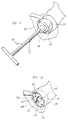
- FIG. 10 A tool for introducing shell member 16 at the joint being operated and positioning the shell member on a surface of a bone to which the socket component 12 is to be affixed is illustrated in Fig. 10 at 72.
- Introducer 72 includes a handle 74 for being grasped by a surgeon and a head or retaining member 76 coupled with handle 74 for retaining or holding shell member 16 upon the introducer.
- Handle 74 can have various configurations and sizes to facilitate grasping by a surgeon and to access the joint being operated. As illustrated in Fig.
- handle 74 has an elongate T-shaped configuration including an elongate central cylindrical shank 78 and a cylindrical cross-piece 80 perpendicularly joined to an end of the shank with a longitudinal axis of the handle being coaxial with shank 78.
- a cylindrical collar 82 at an end of shank 78 opposite cross-piece 80 is received in a recess in retaining member 76 thereby coupling handle 74 with the retaining member.
- Retaining member 76 has a generally cylindrical forward portion 84 and a partial spherical end portion 86 joined to forward portion 84 at a circular junction 88.
- the forward and end portions 84 and 86 are of a size and configuration to be closely received in intermediate and end cavity sections 30 and 32, respectively, of cavity 18 of shell member 16 with the junctions 36 and 88 substantially aligned.
- Forward portion 84 has a length greater than the length of intermediate cavity section 30 to extend lengthwise from junction 88 to a planar forward wall 90 disposed forwardly of the rim 24 of shell member 16 when the retaining member 76 is received in the cavity 18.
- Forward wall 90 is contained in a plane perpendicular to the handle longitudinal axis, and the recess receiving collar 82 is concentrically disposed in the forward wall.
- Retaining member 76 has a longitudinal axis perpendicular with a plane containing junction 88, the retaining member longitudinal axis being angularly offset from the longitudinal axis of handle 74 by an angle that is the same as the angle between the longitudinal axis of cavity 18 and the longitudinal axis of shell 16.
- Various detent mechanisms such as ball detent 92, can be provided to releasably retain the shell member 16 upon the retaining member 76.
- Ball detent 92 is disposed along the periphery of forward portion 84 of retaining member 76 to engage the wall of intermediate cavity section 30 and resist removal of shell member 16 from introducer 72.
- the acetabulum and the upper end of the femur of a patient are prepared in accordance with well known surgical techniques to receive socket component 12 and femoral stem component 14, respectively.
- the natural femoral head is removed and a cavity is prepared in the femur upper end to receive stem 66 of the stem component 14.
- prosthetic stem component 14 may be eliminated allowing the natural bone structure of the femur to serve as the ball of the joint.
- the acetabulum is typically prepared by reaming to remove diseased or damaged tissue and form a hemispherical or partial spherical recess 23 for receiving shell member 16.
- trial socket and stem components are positioned on the prepared bone surfaces.
- a prosthetic stem component such as one corresponding to stem component 14 best suited anatomically and physiologically to the patient is temporarily installed on the femur with the stem 66 of the stem component positioned in the prepared cavity.
- a trial socket component such as one corresponding to socket component 12, best suited to the patient is selected by the surgeon, and the shell member 16 of the trial socket component is inserted in the prepared acetabular recess 23.
- the surgeon When inserting trial shell member 16, the surgeon first determines the most desirable orientation for the shell member within or relative to the acetabular recess 23 to obtain a certain size or angle of overhang at a certain location to most advantageously orient the socket opening to prevent dislocation of the ball of stem component 14 therefrom. This determination is made in accordance with the anatomical and physiological features of the patient, and the indicia markings of the shell member 16 allow the surgeon to select a desired size or angle of overhang and to position the selected overhang where desired.
- the surgeon determines the size of socket opening angle desired and then positions the indicia marking corresponding to the desired angle posteriorly along the acetabular recess at the desired location to resist dislocation.
- Dislocation of the joint anteriorly can be avoided by inserting the shell member 16 in the acetabular recess 23 with an indicia marking corresponding to a desired socket opening angle positioned anteriorly along the acetabular recess at the location desired to resist dislocation of the joint.
- Trial shell 16 can be inserted on the acetabulum in many various ways including via introducer 72 as will be explained further below.
- a trial liner such as one corresponding to liner 20 is inserted within the cavity 18 of the shell member.
- the liner 20 is dialed or rotated to align reference mark 57 with the indicia marking corresponding to the size of angle previously selected.
- the trial components are tested by moving the patient's leg. If it is discovered upon moving the patient's leg that there is a tendency toward dislocation of the joint, the liner 20 can be dialed or rotated to change the size of the angle and the version or orientation of socket opening 60 to avoid dislocation.
- a positioning mark 94 can be provided on forward wall 90 for being aligned with second indicia marking 61.
- the longitudinal axis of the handle 74 will be aligned with the longitudinal axis of the shell to allow insertion of shell 16 upon a bone surface utilizing conventional techniques. While grasping handle 74, the surgeon inserts the shell member 16 in the prepared acetabular recess 23 with a press fit. Shell member 16 is inserted in the acetabular recess 23 in a direction of insertion aligned with the longitudinal axis of handle 74 allowing the shell to be inserted straight into the acetabular recess.
- the final shell member 16 is inserted with the indicia marking corresponding to the desired size or angle for the socket opening positioned relative to the acetabular recess 23 as determined by the trial procedure, and the surgeon rotates or turns handle 74 to obtain the correct position of the shell member 16 for insertion.
- Shell member 16 is illustrated in Fig. 11 as being inserted in the acetabular recess 23 with indicia marking 63 located anteriorly of the acetabular recess as may be desirable when conducting surgery anteriorly.
- various anatomical landmarks as well as reference marks etched into the bone adjacent the acetabular recess can be utilized for alignment with the selected indicia marking.
- the left or right indicia markings can be utilized.
- introducer 72 is withdrawn.
- ball detent 92 is utilized, the shell member 16 can be held in place while the introducer is withdrawn with force sufficient to overcome the frictional lock of the ball detent.
- a final liner 20 is then inserted in the cavity 18 of the shell member 16, and the liner is rotated or dialed to align the reference mark 57 with the selected indicia marking as illustrated in Fig. 12 wherein the reference mark 57 is aligned with left indicia marking 63 corresponding to an angle of 10°.
- the liner 20 can be secured in shell member 16 with various diverse types of locking mechanisms.
- the head or ball of the stem component is then inserted in socket 62 and, if further adjustments are necessary to ensure stability of the joint, the liner 20 can be rotated or dialed to adjust the size of the angle and the orientation of the socket opening 60 to prevent dislocation.
- the maximum thickness of rear portion 50 is positioned posteriorly for increased coverage of the ball or head posteriorly, anteversion of the liner anteriorly due to a part of the forward portion 54 entering the cavity 18 permits increased motion toward the front of the joint.
- retroversion of the liner posteriorly is increased to permit increased motion posteriorly.
Landscapes
- Health & Medical Sciences (AREA)
- Orthopedic Medicine & Surgery (AREA)
- Transplantation (AREA)
- Heart & Thoracic Surgery (AREA)
- Cardiology (AREA)
- Oral & Maxillofacial Surgery (AREA)
- Engineering & Computer Science (AREA)
- Biomedical Technology (AREA)
- Vascular Medicine (AREA)
- Life Sciences & Earth Sciences (AREA)
- Animal Behavior & Ethology (AREA)
- General Health & Medical Sciences (AREA)
- Public Health (AREA)
- Veterinary Medicine (AREA)
- Physical Education & Sports Medicine (AREA)
- Prostheses (AREA)
Claims (29)
- Prothetische Pfannenkomponente (12) für anatomische Gelenkverbindungen, umfassend:ein Schalenelement (16) zur Befestigung an einem ersten Knochen des Gelenks und mit einer Schalenelementlängsachse, einer Ausnehmung (18) und einer mit der Ausnehmung kommunizierenden Schalenelementöffnung (26), wobei die Schalenelementöffnung (26) in einer zur Schalenelementlängsachse senkrechten ersten Ebene (P1) angeordnet ist, wobei die Ausnehmung (18) eine Ausnehmungslängsachse aufweist, die gegenüber der Schalenelementlängsachse winkelversetzt ist; undeinen Einsatz (20) zur drehbaren Aufnahme in der Ausnehmung (18) durch die Schalenelementöffnung (26) sowie mit einer Pfanne (62) und einer mit der Pfanne (62) kommunizierenden Einsatzöffnung (60), wobei das Schalenelement (16) und der Einsatz (20) ausgebildet sind, um die Einsatzöffnung (60) so zu positionieren, dass sie über die Schalenelementöffnung (26) hinausragt, so dass die Einsatzöffnung (60) in einer unter einem Winkel mit der ersten Ebene (P1) angeordneten zweiten Ebene (P5) angeordnet ist, wenn der Einsatz (20) in der Ausnehmung (18) aufgenommen worden ist, und um es zu ermöglichen, die Größe des besagten Winkels ansprechend auf eine Drehung des Einsatzes (20) in bezug zum Schalenelement (16) um die Ausnehmungslängsachse zu verändern.
- Prothetische Pfannenkomponente nach Anspruch 1, bei der das Schalenelement (16) eine Außenseite (22) zur Befestigung am ersten Knochen des Gelenks einschließt, wobei die Außenseite (22) an einem vorderen Rand (24) endet, der in der ersten Ebene (P1) angeordnet ist und die Schalenelementöffnung (26) begrenzt.
- Prothetische Pfannenkomponente nach Anspruch 2, bei der die Ausnehmung (18) einen vorderen Ausnehmungsabschnitt (28), einen endseitigen Ausnehmungsabschnitt (32) und einen dazwischenliegenden Ausnehmungsabschnitt (30) umfasst und der vordere Ausnehmungsabschnitt (28) eine Länge aufweist, die sich vom vorderen Rand (24) bis zu einer Plattform (34) im Schalenelement (16) erstreckt, wobei die Plattform (34) in einer unter einem spitzen Winkel zur ersten Ebene (P1) angeordneten dritten Ebene (P2) enthalten ist, wobei der vordere Ausnehmungsabschnitt (28) entsprechend dem spitzen Winkel abgeschrägt ist, so dass er eine größte Länge aufweist, wo der Winkelabstand zwischen der ersten Ebene (P1) und der zweiten Ebene (P5) am größten ist, und eine kleinste Länge, wo der Winkelabstand zwischen der ersten Ebene (P1) und der zweiten Ebene (P5) am kleinsten ist.
- Prothetische Pfannenkomponente nach Anspruch 3, bei der der Einsatz (20) eine Einsatzlängsachse, ein Befestigungsende (42) zur Aufnahme im dazwischenliegenden und im endseitigen Ausnehmungsabschnitt (30,32) sowie eine Kappe (44) umfasst, die mit dem Befestigungsende (42) verbunden ist und die Einsatzöffnung (60) enthält, wobei die Kappe (44) einen Teil (50) zur Aufnahme im vorderen Ausnehmungsabschnitt (28) aufweist, wobei der Teil (50) entsprechend der Abschrägung des vorderen Ausnehmungsabschnitts (28) abgeschrägt ist, so dass er eine der größten Länge entsprechende größte Dicke und eine der kleinsten Länge entsprechende kleinste Dicke aufweist.
- Prothetische Pfannenkomponente nach Anspruch 4, bei der der Einsatz (20) in Bezug zum Schalenelement (16) zwischen einer Neutralstellung, in der die größte Dicke mit der größten Länge ausgerichtet ist und die zweite Ebene (P5) unter einem kleinsten Winkel zur ersten Ebene (P1) angeordnet ist, und einer Extremstellung drehbar ist, in der die größte Dicke mit der kleinsten Länge ausgerichtet ist und die zweite Ebene (P5) unter einem größten Winkel zur ersten Ebene (P1) angeordnet ist.
- Prothetische Pfannenkomponente nach Anspruch 5 und weiter umfassend eine Bezugsmarkierung (57) auf dem Einsatz (20) sowie eine erste und zweite Indexmarkierung (59,61) auf dem Schalenelement (16) zur Ausrichtung mit der Bezugsmarkierung (57) in der Neutral- bzw. Extremstellung.
- Prothetische Pfannenkomponente nach Anspruch 6, bei der der Einsatz in Bezug zum Schalenelement (16) in eine erste Zwischenstellung zwischen der Neutral- und der Extremstellung drehbar ist, in der die zweite Ebene (P5) unter einem ersten Zwischenwinkel zur ersten Ebene (P1) angeordnet ist, der größer ist als der kleinste Winkel und kleiner als der größte Winkel.
- Prothetische Pfannenkomponente nach Anspruch 7, bei der der Einsatz (20) in Bezug zum Schalenelement (16) in eine zweite Zwischenstellung zwischen der ersten Zwischenstellung und der Extremstellung drehbar ist, in der die zweite Ebene (P5) unter einem zweiten Zwischenwinkel zur ersten Ebene (P1) angeordnet ist, der größer ist als der erste Zwischenwinkel und kleiner als der größte Winkel.
- Prothetische Pfannenkomponente nach Anspruch 8 und weiter umfassend eine dritte und vierte Indexmarkierung (63,65) auf dem Schalenelement (16) zur Ausrichtung mit der Bezugsmarkierung (57) in der ersten bzw. zweiten Zwischenstellung.
- Prothetische Pfannenkomponente nach Anspruch 4, bei der das Befestigungsende (42) eine Oberfläche (52) einschließt, um mit der Plattform (34) in Eingriff zu treten, wenn der Einsatz (20) in der Ausnehmung (18) aufgenommen wird.
- Prothetische Pfannenkomponente nach Anspruch 10, bei der die Einsatzlängsachse mit der Ausnehmungslängsachse fluchtet, wenn der Einsatz (20) in der Ausnehmung (18) aufgenommen wird.
- Prothetische Pfannenkomponente nach Anspruch 11, bei der der Einsatz (20) einen Rand (56) zum Einpassen in den vorderen Rand (24) einschließt.
- Prothetische Pfannenkomponente nach Anspruch 12, bei der der Einsatz (20) in Bezug zum Schalenelement (60) zwischen einer Neutralstellung, in der die Einsatzöffnung (16) unter einem vorbestimmten kleinsten Winkel zur Schalenelementöffnung (26) angeordnet ist, und einer Extremstellung drehbar ist, in der die Einsatzöffnung (60) unter einem größten vorbestimmten Winkel zur Schalenelementöffnung (26) angeordnet ist.
- Prothetische Pfannenkomponente nach Anspruch 13, bei der der Rand (56) in einer Ebene (P4) angeordnet ist, die in der Neutralstellung im wesentlichen mit der ersten Ebene (P1) übereinstimmt.
- Prothetische Pfannenkomponente nach Anspruch 14, bei der die Ebene (P4) des Randes die erste Ebene (P1) schneidet, wenn der Einsatz (20) aus der Neutralstellung auf die Extremstellung zu bewegt wird.
- Prothetische Pfannenkomponente nach Anspruch 15, bei der der Einsatz (20) ein überstehendes Teilstück (54) einschließt, das in der Neutralstellung über die erste Ebene (P1) hinausragt, und ein Teil des überstehenden Teilstücks (54) in die Ausnehmung (18) eindringt, wenn der Einsatz (20) aus der Neutralstellung auf die Extremstellung zu bewegt wird.
- Prothetische Pfannenkomponente nach Anspruch 16, bei der der Teil des überstehenden Teilstücks (54), der in die Ausnehmung (18) eindringt, größer wird, während der Einsatz (20) aus der Neutralstellung auf die Extremstellung zu bewegt wird.
- Prothetische Pfannenkomponente nach Anspruch 17, bei der der Einsatz (20) um 180° aus der Neutralstellung in die Extremstellung drehbar ist.
- Prothetische Pfannenkomponente nach Anspruch 18, bei der der Einsatz (20) um ungefähr 60° aus der Neutralstellung in eine erste Zwischenstellung drehbar ist, in der die Einsatzöffnung (60) unter einem ersten Zwischenwinkel zur Schalenelementöffnung (26) angeordnet ist.
- Prothetische Pfannenkomponente nach Anspruch 19, bei der der Einsatz (20) um ungefähr 120° aus der Neutralstellung in eine zweite Zwischenstellung drehbar ist, in der die Einsatzöffnung (60) in einer zweiten Zwischenstellung angeordnet ist, in der die Einsatzöffnung (60) unter einem zweiten Zwischenwinkel zur Schalenelementöffnung (26) angeordnet ist.
- Prothetische Pfannenkomponente nach Anspruch 20, bei der der Winkel zwischen der Einsatzöffnung (60) und der Schalenelementöffnung (26) in Schritten von 5° zunimmt, während der Einsatz (20) aus der Neutralstellung in die erste Zwischenstellung, aus der ersten Zwischenstellung in die zweite Zwischenstellung und aus der zweiten Zwischenstellung in die Extremstellung gedreht wird.
- Prothetische Pfannenkomponente nach Anspruch 1 und weiter umfassend eine Einführvorrichtung (72) zum Positionieren des Schalenelements (16) auf einer Oberfläche des ersten Knochens des Gelenks, wobei die Einführvorrichtung (72) ein Halteelement (76) zur Aufnahme in der Ausnehmung (18) und einen mit dem Halteelement (76) verbundenen Griff (74) einschließt, wobei das Halteelement (76) eine Längsachse aufweist, und der Griff (74) eine Längsachse aufweist, die gegenüber der Längsachse des Halteelements winkelversetzt ist, mit einem Winkelversatz, welcher derselbe ist, wie der Winkelversatz der Schalenelementlängsachse gegenüber der Ausnehmungslängsachse, wobei das Halteelement (76) in der Ausnehmung (18) aufnehmbar ist, wenn die Längsachse des Halteelements mit der Ausnehmungslängsachse fluchtet und die Längsachse des Griffs mit der Schalenelementlängsachse fluchtet, um es zu ermöglichen, das Schalenelement (16) in einer mit der Längsachse des Griffs fluchtenden Einführrichtung auf der Knochenoberfläche einzusetzen.
- Prothetische Pfannenkomponente nach Anspruch 2, bei der die Außenseite (22) gestaltet ist, um sie auf einem vorbereiteten Acetabulum zu befestigen, und weiter umfassend ein Kugelelement (68), um es dem Acetabulum entsprechend am oberen Ende des Femur zu befestigen, wobei das Kugelelement eine Gestalt aufweist, um durch die Einsatzöffnung (60) hindurch drehbar in der Pfanne (62) aufgenommen zu werden.
- Prothetische Pfannenkomponente nach Anspruch 23, bei der der Einsatz (20) in Bezug zum Schalenelement (16) zwischen einer Neutralstellung, in der die zweite Ebene (P5) unter einem kleinsten Winkel zur ersten Ebene (P1) angeordnet ist, und einer Extremstellung drehbar ist, in der die zweite Ebene (P5) unter einem größten Winkel zur ersten Ebene (P1) angeordnet ist.
- Prothetische Pfannenkomponente nach Anspruch 24, bei der die zweite Ebene (P5) in der Extremstellung unter einem Winkel von 20° zur ersten Ebene (P1) angeordnet ist.
- Prothetische Pfannenkomponente nach Anspruch 25, bei der die zweite Ebene (P5) in der Extremstellung unter einem Winkel von 5° zur ersten Ebene (P1) angeordnet ist.
- Prothetische Pfannenkomponente nach Anspruch 3, bei der die dritte Ebene (P2) unter einem Winkel von ungefähr 7 ½° zur ersten Ebene (P1) angeordnet ist.
- Prothetische Pfannenkomponente nach Anspruch 22, bei der das Halteelement (76) eine zur Gestalt der Ausnehmung komplementäre Gestalt aufweist.
- Prothetische Pfannenkomponente nach Anspruch 28, bei der der Griff (74) manuell um die Längsachse des Griffs drehbar ist, um das Schalenelement (16) um die Schalenelementlängsachse zu drehen.
Applications Claiming Priority (2)
| Application Number | Priority Date | Filing Date | Title |
|---|---|---|---|
| US08/024,206 US5507824A (en) | 1993-02-23 | 1993-02-23 | Adjustable prosthetic socket component, for articulating anatomical joints |
| US24206 | 1996-08-20 |
Publications (3)
| Publication Number | Publication Date |
|---|---|
| EP0612509A2 EP0612509A2 (de) | 1994-08-31 |
| EP0612509A3 EP0612509A3 (de) | 1995-02-22 |
| EP0612509B1 true EP0612509B1 (de) | 1999-07-21 |
Family
ID=21819393
Family Applications (1)
| Application Number | Title | Priority Date | Filing Date |
|---|---|---|---|
| EP94200433A Expired - Lifetime EP0612509B1 (de) | 1993-02-23 | 1994-02-22 | Einstellbares Prothesenpfannenteil für anatomische Gelenke |
Country Status (5)
| Country | Link |
|---|---|
| US (1) | US5507824A (de) |
| EP (1) | EP0612509B1 (de) |
| AU (1) | AU5510394A (de) |
| CA (1) | CA2115512A1 (de) |
| DE (1) | DE69419540T2 (de) |
Cited By (6)
| Publication number | Priority date | Publication date | Assignee | Title |
|---|---|---|---|---|
| US7597715B2 (en) | 2005-04-21 | 2009-10-06 | Biomet Manufacturing Corp. | Method and apparatus for use of porous implants |
| US8021432B2 (en) | 2005-12-05 | 2011-09-20 | Biomet Manufacturing Corp. | Apparatus for use of porous implants |
| US8066778B2 (en) | 2005-04-21 | 2011-11-29 | Biomet Manufacturing Corp. | Porous metal cup with cobalt bearing surface |
| US8123814B2 (en) | 2001-02-23 | 2012-02-28 | Biomet Manufacturing Corp. | Method and appartus for acetabular reconstruction |
| US8266780B2 (en) | 2005-04-21 | 2012-09-18 | Biomet Manufacturing Corp. | Method and apparatus for use of porous implants |
| US8292967B2 (en) | 2005-04-21 | 2012-10-23 | Biomet Manufacturing Corp. | Method and apparatus for use of porous implants |
Families Citing this family (143)
| Publication number | Priority date | Publication date | Assignee | Title |
|---|---|---|---|---|
| US7077867B1 (en) | 1994-08-12 | 2006-07-18 | Diamicron, Inc. | Prosthetic knee joint having at least one diamond articulation surface |
| US7678325B2 (en) * | 1999-12-08 | 2010-03-16 | Diamicron, Inc. | Use of a metal and Sn as a solvent material for the bulk crystallization and sintering of diamond to produce biocompatbile biomedical devices |
| US6494918B1 (en) | 2000-01-30 | 2002-12-17 | Diamicron, Inc. | Component for a prosthetic joint having a diamond load bearing and articulation surface |
| US6425922B1 (en) | 2000-01-30 | 2002-07-30 | Diamicron, Inc. | Prosthetic hip joint having at least one sintered polycrystalline diamond compact articulation surface |
| US6596225B1 (en) | 2000-01-31 | 2003-07-22 | Diamicron, Inc. | Methods for manufacturing a diamond prosthetic joint component |
| US6793681B1 (en) | 1994-08-12 | 2004-09-21 | Diamicron, Inc. | Prosthetic hip joint having a polycrystalline diamond articulation surface and a plurality of substrate layers |
| US7396505B2 (en) | 1994-08-12 | 2008-07-08 | Diamicron, Inc. | Use of CoCrMo to augment biocompatibility in polycrystalline diamond compacts |
| US6290726B1 (en) | 2000-01-30 | 2001-09-18 | Diamicron, Inc. | Prosthetic hip joint having sintered polycrystalline diamond compact articulation surfaces |
| US6517583B1 (en) | 2000-01-30 | 2003-02-11 | Diamicron, Inc. | Prosthetic hip joint having a polycrystalline diamond compact articulation surface and a counter bearing surface |
| US7494507B2 (en) * | 2000-01-30 | 2009-02-24 | Diamicron, Inc. | Articulating diamond-surfaced spinal implants |
| US7396501B2 (en) | 1994-08-12 | 2008-07-08 | Diamicron, Inc. | Use of gradient layers and stress modifiers to fabricate composite constructs |
| US5683472A (en) * | 1995-12-29 | 1997-11-04 | Johnson & Johnson Professional, Inc. | Femoral stem attachment for a modular knee prosthesis |
| US5879401A (en) * | 1996-05-17 | 1999-03-09 | Johnson & Johnson Professional, Inc. | Acetabular trial |
| DK0927010T3 (da) | 1996-09-11 | 2003-02-10 | Plus Endoprothetik Ag | Tibia-del af en knæledsendoprotese |
| DE19647155C2 (de) * | 1996-11-14 | 1998-11-19 | Plus Endoprothetik Ag | Implantat |
| ES2192277T3 (es) * | 1996-11-21 | 2003-10-01 | Plus Endoprothetik Ag | Cotilo articular para una endoprotesis de la articulacion coxofemoral. |
| FR2781362B1 (fr) * | 1998-07-24 | 2000-11-24 | Michel Henry Fessy | Cupule de cotyle pour prothese de hanche |
| FR2782262B1 (fr) * | 1998-08-17 | 2001-02-09 | Michel Porte | Cotyle d'essai ou implantable a orientation reglable |
| US6162255A (en) * | 1998-10-15 | 2000-12-19 | Depuy Orthopaedics, Inc. | Stem offset mechanism for joint prosthesis |
| IT1303805B1 (it) * | 1998-12-01 | 2001-02-23 | Bridgehall Consultants Ltd | Cotile da revisione per impiego nel trattamento di patologiedell'anca. |
| US6702854B1 (en) | 1999-06-01 | 2004-03-09 | Apex Surgical, Llc | Implantable joint prosthesis |
| US6315718B1 (en) | 1999-10-04 | 2001-11-13 | Minnesota Scientific, Inc. | Method for hip retraction |
| US7569176B2 (en) * | 1999-12-08 | 2009-08-04 | Diamicron, Inc. | Method for making a sintered superhard prosthetic joint component |
| US7556763B2 (en) * | 1999-12-08 | 2009-07-07 | Diamicron, Inc. | Method of making components for prosthetic joints |
| US6709463B1 (en) | 2000-01-30 | 2004-03-23 | Diamicron, Inc. | Prosthetic joint component having at least one solid polycrystalline diamond component |
| US20050203630A1 (en) * | 2000-01-30 | 2005-09-15 | Pope Bill J. | Prosthetic knee joint having at least one diamond articulation surface |
| US6410877B1 (en) | 2000-01-30 | 2002-06-25 | Diamicron, Inc. | Methods for shaping and finishing prosthetic joint components including polycrystalline diamond compacts |
| US8603181B2 (en) * | 2000-01-30 | 2013-12-10 | Dimicron, Inc | Use of Ti and Nb cemented in TiC in prosthetic joints |
| US20100025898A1 (en) * | 2000-01-30 | 2010-02-04 | Pope Bill J | USE OF Ti AND Nb CEMENTED TiC IN PROSTHETIC JOINTS |
| US20040199260A1 (en) * | 2000-01-30 | 2004-10-07 | Pope Bill J. | Prosthetic joint component having at least one sintered polycrystalline diamond compact articulation surface and substrate surface topographical features in said polycrystalline diamond compact |
| US6488715B1 (en) | 2000-01-30 | 2002-12-03 | Diamicron, Inc. | Diamond-surfaced cup for use in a prosthetic joint |
| US7682398B2 (en) * | 2000-03-14 | 2010-03-23 | Smith & Nephew, Inc. | Variable geometry rim surface acetabular shell liner |
| KR20020083166A (ko) * | 2000-03-14 | 2002-11-01 | 스미스 앤드 네퓨, 인크. | 가변 기하학적 림 표면 관골구 쉘 라이너 |
| AU783205C (en) | 2000-03-15 | 2006-08-17 | Depuy Orthopaedics, Inc. | Prosthetic cup assembly which includes components possessing self-locking taper |
| US20020016634A1 (en) * | 2000-07-28 | 2002-02-07 | Brian Maroney | Device and method for positioning an eccentric humeral head of a humerus prothesis for a shoulder arthroplasty |
| DE10036987A1 (de) * | 2000-07-29 | 2002-02-07 | Klaus Draenert | Modularer Pfannenersatz |
| DE20102819U1 (de) * | 2001-02-17 | 2002-06-27 | K.A. Schmersal Gmbh & Co, 42279 Wuppertal | Sicherheitszuhaltung für eine Tür, Klappe o.dgl. |
| US7713306B2 (en) * | 2001-02-23 | 2010-05-11 | Biomet Manufacturing Corp. | Method and apparatus for acetabular reconstruction |
| US7291177B2 (en) | 2001-02-23 | 2007-11-06 | Biomet Manufacturing Corp. | Method and apparatus for acetabular reconstruction |
| US7547307B2 (en) | 2001-02-27 | 2009-06-16 | Smith & Nephew, Inc. | Computer assisted knee arthroplasty instrumentation, systems, and processes |
| US6655845B1 (en) * | 2001-04-22 | 2003-12-02 | Diamicron, Inc. | Bearings, races and components thereof having diamond and other superhard surfaces |
| US20030019106A1 (en) * | 2001-04-22 | 2003-01-30 | Diamicron, Inc. | Methods for making bearings, races and components thereof having diamond and other superhard surfaces |
| US8795379B2 (en) | 2001-07-11 | 2014-08-05 | Biomet Manufacturing, Llc | Variable prosthesis |
| US6942699B2 (en) | 2001-07-11 | 2005-09-13 | Biomet, Inc. | Shoulder prosthesis |
| FR2827154B1 (fr) * | 2001-07-16 | 2004-04-30 | Jean Yves Lazennec | Implant cotyloidien pour prothese de hanche |
| KR100458638B1 (ko) * | 2001-09-10 | 2004-12-03 | 삼성테크윈 주식회사 | 인공 고관절용 비구 컵 |
| US7326253B2 (en) * | 2001-11-16 | 2008-02-05 | Depuy Products, Inc. | Prosthetic cup assembly having increased assembly congruency |
| US20070093696A1 (en) * | 2001-11-21 | 2007-04-26 | The LeVahn Intellectual Property Holding Company, LLC | Method of table mounted retraction in hip surgery and surgical retractor |
| US20050119697A1 (en) * | 2001-11-21 | 2005-06-02 | Minnesota Scientific, Inc. | Method of table mounted retraction in hip surgery |
| DE10200690B4 (de) * | 2002-01-10 | 2005-03-03 | Intraplant Ag | Hilfsmittel zur Implantation einer Hüftgelenkendoprothese |
| AU2003217389B2 (en) | 2002-02-11 | 2008-10-30 | Smith & Nephew, Inc. | Image-guided fracture reduction |
| US7175663B1 (en) * | 2003-10-08 | 2007-02-13 | Biomet Manufacturing Corp. | Shoulder implant assembly |
| US8062376B2 (en) * | 2002-07-10 | 2011-11-22 | Biomet Manufacturing Corp. | Shoulder implant assembly |
| US6926740B2 (en) | 2002-12-13 | 2005-08-09 | Depuy Products, Inc. | Modular orthopaedic implant apparatus and method |
| US7854737B2 (en) * | 2002-12-20 | 2010-12-21 | Depuy Products, Inc. | Instrument and associated method of trailing for modular hip stems |
| US20040122439A1 (en) * | 2002-12-20 | 2004-06-24 | Dwyer Kimberly A. | Adjustable biomechanical templating & resection instrument and associated method |
| US7022141B2 (en) * | 2002-12-20 | 2006-04-04 | Depuy Products, Inc. | Alignment device for modular implants and method |
| US7235106B2 (en) | 2002-12-20 | 2007-06-26 | Depuy Products, Inc. | Modular hip stems and associated method of trialing |
| US7111401B2 (en) * | 2003-02-04 | 2006-09-26 | Eveready Battery Company, Inc. | Razor head having skin controlling means |
| US7887544B2 (en) * | 2003-03-10 | 2011-02-15 | Tornier Sas | Ancillary tool for positioning a glenoid implant |
| US7297166B2 (en) * | 2003-06-25 | 2007-11-20 | Depuy Products, Inc. | Assembly tool for modular implants and associated method |
| US8998919B2 (en) | 2003-06-25 | 2015-04-07 | DePuy Synthes Products, LLC | Assembly tool for modular implants, kit and associated method |
| US20040267267A1 (en) * | 2003-06-25 | 2004-12-30 | Daniels David Wayne | Non-linear reamer for bone preparation and associated method |
| US7582092B2 (en) * | 2003-06-25 | 2009-09-01 | Depuy Products, Inc. | Assembly tool for modular implants and associated method |
| US7074224B2 (en) * | 2003-06-25 | 2006-07-11 | Depuy Products, Inc. | Modular tapered reamer for bone preparation and associated method |
| FR2859099B1 (fr) * | 2003-08-25 | 2006-01-06 | Tornier Sa | Composant glenoidien de prothese d'epaule et prothese totale d'epaule incorporant un tel composant |
| US20050133277A1 (en) * | 2003-08-28 | 2005-06-23 | Diamicron, Inc. | Superhard mill cutters and related methods |
| GB0321582D0 (en) * | 2003-09-15 | 2003-10-15 | Benoist Girard Sas | Prosthetic acetabular cup and prosthetic femoral joint incorporating such a cup |
| US7862570B2 (en) | 2003-10-03 | 2011-01-04 | Smith & Nephew, Inc. | Surgical positioners |
| US8070820B2 (en) | 2003-10-08 | 2011-12-06 | Biomet Manufacturing Corp. | Shoulder implant assembly |
| DE112004001893B4 (de) * | 2003-10-09 | 2018-06-21 | Omni Life Science, Inc. | Kegelförmige Gelenksprothese |
| US7764985B2 (en) | 2003-10-20 | 2010-07-27 | Smith & Nephew, Inc. | Surgical navigation system component fault interfaces and related processes |
| AU2004291146B2 (en) | 2003-11-14 | 2011-08-25 | Smith & Nephew, Inc. | Adjustable surgical cutting systems |
| FR2863865B1 (fr) * | 2003-12-19 | 2006-10-06 | Tornier Sa | Prothese d'epaule ou de hanche et son procede de montage |
| US7785328B2 (en) * | 2003-12-30 | 2010-08-31 | Depuy Products, Inc. | Minimally invasive bone miller apparatus |
| US7753960B2 (en) * | 2004-02-26 | 2010-07-13 | Omni Life Science, Inc. | Modular knee prosthesis |
| JP2007531596A (ja) | 2004-03-31 | 2007-11-08 | スミス アンド ネフュー インコーポレーテッド | 基準アレイ入力装置を提供する方法及び装置 |
| GB0407624D0 (en) * | 2004-04-02 | 2004-05-05 | Benoist Girard Sas | Prosthetic femoral joint |
| EP1737375B1 (de) | 2004-04-21 | 2021-08-11 | Smith & Nephew, Inc | Computerunterstützte navigationssysteme für die schulter-arthroplastie |
| FR2871371B1 (fr) * | 2004-06-15 | 2007-04-06 | Tornier Sas | Composant glenoidien de prothese d'epaule, jeu d'elements constitutifs d'un tel composant et prothese totale d'epaule incorporant un tel composant |
| EP1607069B1 (de) * | 2004-06-15 | 2009-12-23 | Tornier | Inverse Schultertotalprothese |
| US8303665B2 (en) | 2004-06-15 | 2012-11-06 | Tornier Sas | Glenoidal component, set of such components and shoulder prosthesis incorporating such a glenoidal component |
| FR2871368B1 (fr) * | 2004-06-15 | 2006-08-25 | Tornier Sas | Jeu de composants humeraux pour prothese totale d'epaule |
| FR2872025B1 (fr) | 2004-06-28 | 2006-08-25 | Tornier Sas | Prothese d'epaule ou de hanche |
| EP1816973A1 (de) * | 2004-12-02 | 2007-08-15 | Smith and Nephew, Inc. | Systeme, verfahren und vorrichtung für automatischen softwarefluss unter verwendung von instrumentenerkennung in der computergestützten chirurgie |
| US20060190089A1 (en) * | 2005-02-18 | 2006-08-24 | Howmedica Osteonics Corp. | Internal adaptor for hip acetabular cage |
| WO2006091704A1 (en) | 2005-02-22 | 2006-08-31 | Smith & Nephew, Inc. | In-line milling system |
| US8052758B1 (en) | 2005-03-09 | 2011-11-08 | Biomet Manufacturing Corp. | Method and apparatus for trialing a modular humeral head |
| GB2424187A (en) * | 2005-03-17 | 2006-09-20 | Biomet Uk Ltd | A Joint prosthesis which includes a shell having a region intended to protrude beyond a bone surface |
| US8449991B2 (en) * | 2005-04-07 | 2013-05-28 | Dimicron, Inc. | Use of SN and pore size control to improve biocompatibility in polycrystalline diamond compacts |
| US20060226570A1 (en) * | 2005-04-12 | 2006-10-12 | Zimmer Technology, Inc. | Method for making a metal-backed acetabular implant |
| US7708783B2 (en) * | 2005-11-04 | 2010-05-04 | Zimmer Technology, Inc. | Rotating constrained liner |
| US20070106392A1 (en) * | 2005-11-08 | 2007-05-10 | Howmedica Osteonics Corp. | Acetabular cup locking mechanism |
| FR2896684B1 (fr) | 2006-02-01 | 2008-09-26 | Tornier Soc Par Actions Simplifiee | Implant tibial a tige offset |
| US7635447B2 (en) * | 2006-02-17 | 2009-12-22 | Biomet Manufacturing Corp. | Method and apparatus for forming porous metal implants |
| CA2646061C (en) | 2006-03-20 | 2014-06-17 | Smith & Nephew, Inc. | Acetabular cup assembly for multiple bearing materials |
| EP1996125B1 (de) * | 2006-03-21 | 2013-05-15 | Tornier, Inc. | Schultergelenkkomponente mit erhöhter fixationsstabilität |
| US20070225821A1 (en) * | 2006-03-21 | 2007-09-27 | Axiom Orthopaedics, Inc. | Femoral and humeral stem geometry and implantation method for orthopedic joint reconstruction |
| WO2007109291A2 (en) * | 2006-03-21 | 2007-09-27 | Axiom Orthopaedics, Inc. | Non-spherical articulating surfaces in shoulder and hip prosthesis |
| US8308811B2 (en) * | 2006-04-11 | 2012-11-13 | Zimmer, Inc. | Acetabular cup conversion ring |
| US20070239283A1 (en) * | 2006-04-11 | 2007-10-11 | Berger Richard A | Acetabular cup conversion ring |
| FR2899790B1 (fr) | 2006-04-13 | 2008-06-13 | Tornier Sas | Composant glenoidien pour prothese totale d'epaule, jeu de tels composants, et prothese totale d'epaule comprenant un tel composant |
| FR2900045B1 (fr) * | 2006-04-21 | 2009-01-16 | Tornier Sas | Prothese d'epaule ou de hanche |
| FR2900571B1 (fr) * | 2006-05-05 | 2008-07-11 | Pierre Roussouly | Cotyle orientable de prothese de hanche |
| DE102007031669A1 (de) * | 2006-08-04 | 2008-09-11 | Ceramtec Ag Innovative Ceramic Engineering | Asymmetrische Gestaltung von Hüftpfannen zur Verringerung der Pfannendeformationen |
| FR2904931B1 (fr) * | 2006-08-18 | 2009-06-05 | Advanced Technical Fabrication | Cotyle a double mobilite a moyens d'extraction |
| US20080053169A1 (en) * | 2006-08-30 | 2008-03-06 | Victoria Marie Ricker | Theft deterrent device for bags |
| US8597298B2 (en) | 2006-09-29 | 2013-12-03 | DePuy Synthes Products, LLC | Proximal reamer |
| FR2911773B1 (fr) * | 2007-01-30 | 2009-03-27 | Tornier Sas | Methode et ensemble d'instrumentation chirurgicale pour poser une prothese totale d'epaule inversee,et prothese correspondante |
| US20090287309A1 (en) | 2007-01-30 | 2009-11-19 | Tornier Sas | Intra-articular joint replacement |
| GB0705911D0 (en) * | 2007-03-28 | 2007-05-09 | Depuy Int Ltd | A head component of an orthopaedic joint prosthesis |
| US8556912B2 (en) | 2007-10-30 | 2013-10-15 | DePuy Synthes Products, LLC | Taper disengagement tool |
| US8518050B2 (en) | 2007-10-31 | 2013-08-27 | DePuy Synthes Products, LLC | Modular taper assembly device |
| EP2259751B1 (de) * | 2008-02-25 | 2014-11-05 | Smith & Nephew, Inc. | System zur abbildung des femurkopfes zur ausrichtung einer gelenkpfannenprothese |
| GB0809721D0 (en) * | 2008-05-28 | 2008-07-02 | Univ Bath | Improvements in or relating to joints and/or implants |
| DE102008047627A1 (de) * | 2008-08-01 | 2010-02-04 | Smith & Nephew Orthopaedics Ag | Positionierhilfe in Form einer selbstfixierenden Probehüftgelenkpfanne |
| CN102281835B (zh) * | 2008-09-16 | 2015-04-08 | Cr巴德公司 | 支架 |
| US8167882B2 (en) * | 2008-09-30 | 2012-05-01 | Depuy Products, Inc. | Minimally invasive bone miller apparatus |
| US8123815B2 (en) | 2008-11-24 | 2012-02-28 | Biomet Manufacturing Corp. | Multiple bearing acetabular prosthesis |
| GB0907036D0 (en) | 2009-04-24 | 2009-06-03 | Depuy Int Ltd | Surgical prostheses |
| US8663359B2 (en) * | 2009-06-26 | 2014-03-04 | Dimicron, Inc. | Thick sintered polycrystalline diamond and sintered jewelry |
| US8308810B2 (en) | 2009-07-14 | 2012-11-13 | Biomet Manufacturing Corp. | Multiple bearing acetabular prosthesis |
| US8383033B2 (en) | 2009-10-08 | 2013-02-26 | Biomet Manufacturing Corp. | Method of bonding porous metal to metal substrates |
| US9408652B2 (en) | 2010-04-27 | 2016-08-09 | Tornier Sas | Intra-articular joint replacement and method |
| US8533921B2 (en) | 2010-06-15 | 2013-09-17 | DePuy Synthes Products, LLC | Spiral assembly tool |
| US9095452B2 (en) | 2010-09-01 | 2015-08-04 | DePuy Synthes Products, Inc. | Disassembly tool |
| FR2966343B1 (fr) | 2010-10-22 | 2012-12-07 | Tornier Sa | Jeu de composants glenoidiens d'une prothese d'epaule |
| CN103813764B (zh) | 2011-04-06 | 2017-04-19 | 德普伊新特斯产品有限责任公司 | 植入修正髋关节假体的器械组件和使用它的整形外科手术 |
| US8702804B2 (en) | 2011-12-02 | 2014-04-22 | Biomet Manufacturing, Llc | Variable prosthesis |
| JP2016514515A (ja) * | 2013-03-21 | 2016-05-23 | コンフォーミス・インコーポレイテッドConforMIS, Inc. | 患者適応性股関節インプラントに関するシステム、方法およびデバイス |
| US10143556B2 (en) * | 2013-04-15 | 2018-12-04 | Eisurf IP-Managment AB | System of designing a guide tool and/ or surgical kit tools and/or an implant comprising a positioning mark |
| US20190231538A1 (en) | 2013-04-15 | 2019-08-01 | Episurf Ip-Management Ab | Method of designing and positioning a medical implant and an implant comprising a positioning mark |
| US9901463B2 (en) * | 2014-04-14 | 2018-02-27 | Mohamed R. Mahfouz | Kinematic alignment and novel femoral and tibial prosthetics |
| EP3050539A1 (de) * | 2015-01-27 | 2016-08-03 | AQ Implants GmbH | Revisionsendoprothese |
| WO2016178946A1 (en) * | 2015-05-01 | 2016-11-10 | Mayo Foundation For Medical Education And Research | Distal radioulnar joint prosthesis and method of use |
| GB201521501D0 (en) | 2015-12-07 | 2016-01-20 | Depuy Ireland | Apparatus and method for aligning an acetabular cup |
| EP3558171B1 (de) | 2016-12-21 | 2021-11-03 | Biomet Manufacturing, LLC | Vorrichtungen zur durchführung eines humeruskopfes |
| WO2018183484A1 (en) | 2017-03-31 | 2018-10-04 | Tornier, Inc. | Modular humeral head |
| ES2832583B2 (es) | 2019-12-10 | 2022-05-05 | Desarrollos Biomecanicos Innovasan S L | Prótesis total de cadera o de hombro e instrumental para su colocación |
| CN109044570A (zh) * | 2018-09-26 | 2018-12-21 | 山东威高海星医疗器械有限公司 | 内衬安装器 |
| US12370052B2 (en) * | 2018-10-02 | 2025-07-29 | Howmedica Osteonics Corp. | Modular humeral head |
| US11857423B2 (en) * | 2021-11-16 | 2024-01-02 | Arthrology Consulting, Llc | Off-center liner for acetabular cup |
| CN114343921B (zh) * | 2021-12-31 | 2023-02-03 | 武汉迈瑞科技有限公司 | 髋臼组件、髋关节假体及组装方法 |
Family Cites Families (30)
| Publication number | Priority date | Publication date | Assignee | Title |
|---|---|---|---|---|
| GB1126961A (en) * | 1965-01-14 | 1968-09-11 | Nat Res Dev | Artificial joints for use in surgery |
| USRE28895E (en) * | 1972-01-13 | 1976-07-13 | United States Surgical Corporation | Artificial hip joint |
| US3903549A (en) * | 1974-06-12 | 1975-09-09 | William Minor Deyerle | Acetabular cup prosthesis component for total or subtotal hip prosthesis system |
| US4004300A (en) * | 1974-10-14 | 1977-01-25 | Thomas Anthony English | Femoral prosthesis |
| US3996625A (en) * | 1975-02-28 | 1976-12-14 | United States Surgical Corporation | Artificial hip joint with novel stem |
| US4040130A (en) * | 1976-10-12 | 1977-08-09 | Laure Prosthetics, Inc. | Wrist joint prosthesis |
| DE2845231A1 (de) * | 1977-10-21 | 1979-05-03 | Indong Oh | Gelenkprothese und verfahren zu deren implantierung |
| US4172296A (en) * | 1978-02-01 | 1979-10-30 | Howmedica, Inc. | Bicentric joint prosthesis |
| DE2829676A1 (de) * | 1978-07-06 | 1980-01-24 | Gmt Medizinische Technik Gmbh | Endoprothese |
| US4883490A (en) * | 1982-01-18 | 1989-11-28 | Indong Oh | Acetabular cup |
| US4623352A (en) * | 1982-01-18 | 1986-11-18 | Indong Oh | Protrusio cup |
| US4437193A (en) * | 1982-01-18 | 1984-03-20 | Indong Oh | Protrusio cup |
| EP0091315B1 (de) * | 1982-04-07 | 1986-07-30 | National Research Development Corporation | Gelenkendoprothese |
| US4642123A (en) * | 1983-03-08 | 1987-02-10 | Joint Medical Products Corporation | Ball and socket bearing for artificial joint |
| US4678472A (en) * | 1983-03-08 | 1987-07-07 | Joint Medical Products Corporation | Ball and socket bearing for artificial joint |
| GB8310675D0 (en) * | 1983-04-20 | 1983-05-25 | Church J C M | Endoprosthetic bone joint devices |
| CA1240101A (en) * | 1983-05-06 | 1988-08-09 | Michael J. Pappas | Multi-component prosthesis with increased wall flexibility facilitating component assembly |
| US4681589A (en) * | 1984-06-01 | 1987-07-21 | Tronzo Raymond G | Adjustable acetabular cup prosthesis as part of a total cup replacement system |
| FR2595941A1 (fr) * | 1986-03-21 | 1987-09-25 | Perrin Max | Cotyle auto-bloquant pour prothese cotyloidienne, notamment pour prothese coxo-femorale |
| EP0265712A1 (de) * | 1986-10-16 | 1988-05-04 | Protek AG | Acetabularteil für eine Hüfttotalprothese |
| FR2620022A1 (fr) * | 1987-09-08 | 1989-03-10 | Teinturier Pierre | Prothese articulaire totale, notamment de la hanche |
| US4904265A (en) * | 1988-09-09 | 1990-02-27 | Boehringer Mannheim Corporation | Cementless acetabular implant |
| ATE85507T1 (de) * | 1989-03-17 | 1993-02-15 | Thull Roger | Hueftgelenkspfanne zur zementfreien implantation in das acetabulum des hueftbeines. |
| US5002577A (en) * | 1989-08-10 | 1991-03-26 | Boehringer Mannheim Corporation | Variable position acetabular cup |
| US5002581A (en) * | 1989-11-03 | 1991-03-26 | Dow Corning Wright Corporation | Modular hip joint prosthesis with adjustable anteversion |
| US5171243A (en) * | 1991-02-13 | 1992-12-15 | Pfizer Hospital Products Group, Inc. | Acetabular cup positioning insert |
| US5176711A (en) * | 1991-03-06 | 1993-01-05 | Grimes James B | Acetabular revision system |
| US5192329A (en) * | 1991-03-07 | 1993-03-09 | Joint Medical Products Corporation | Oblong acetabular cup |
| US5169399A (en) * | 1991-10-17 | 1992-12-08 | Boehringer Mannheim Corporation | Acetabular cup impactor |
| US5171285A (en) * | 1992-02-18 | 1992-12-15 | Zimmer, Inc. | Acetabular cup with shiftable elevated rim liner |
-
1993
- 1993-02-23 US US08/024,206 patent/US5507824A/en not_active Expired - Fee Related
-
1994
- 1994-02-11 CA CA002115512A patent/CA2115512A1/en not_active Abandoned
- 1994-02-14 AU AU55103/94A patent/AU5510394A/en not_active Abandoned
- 1994-02-22 EP EP94200433A patent/EP0612509B1/de not_active Expired - Lifetime
- 1994-02-22 DE DE69419540T patent/DE69419540T2/de not_active Expired - Fee Related
Cited By (9)
| Publication number | Priority date | Publication date | Assignee | Title |
|---|---|---|---|---|
| US8123814B2 (en) | 2001-02-23 | 2012-02-28 | Biomet Manufacturing Corp. | Method and appartus for acetabular reconstruction |
| US8551181B2 (en) | 2001-02-23 | 2013-10-08 | Biomet Manufacturing, Llc | Method and apparatus for acetabular reconstruction |
| US9375316B2 (en) | 2001-02-23 | 2016-06-28 | Biomet Manufacturing, Llc. | Method and apparatus for acetabular reconstruction |
| US7597715B2 (en) | 2005-04-21 | 2009-10-06 | Biomet Manufacturing Corp. | Method and apparatus for use of porous implants |
| US8066778B2 (en) | 2005-04-21 | 2011-11-29 | Biomet Manufacturing Corp. | Porous metal cup with cobalt bearing surface |
| US8197550B2 (en) | 2005-04-21 | 2012-06-12 | Biomet Manufacturing Corp. | Method and apparatus for use of porous implants |
| US8266780B2 (en) | 2005-04-21 | 2012-09-18 | Biomet Manufacturing Corp. | Method and apparatus for use of porous implants |
| US8292967B2 (en) | 2005-04-21 | 2012-10-23 | Biomet Manufacturing Corp. | Method and apparatus for use of porous implants |
| US8021432B2 (en) | 2005-12-05 | 2011-09-20 | Biomet Manufacturing Corp. | Apparatus for use of porous implants |
Also Published As
| Publication number | Publication date |
|---|---|
| EP0612509A2 (de) | 1994-08-31 |
| US5507824A (en) | 1996-04-16 |
| CA2115512A1 (en) | 1994-08-24 |
| DE69419540T2 (de) | 1999-11-11 |
| DE69419540D1 (de) | 1999-08-26 |
| AU5510394A (en) | 1994-09-01 |
| EP0612509A3 (de) | 1995-02-22 |
Similar Documents
| Publication | Publication Date | Title |
|---|---|---|
| US5507824A (en) | Adjustable prosthetic socket component, for articulating anatomical joints | |
| US7846212B2 (en) | Modular orthopaedic implant apparatus | |
| US5176711A (en) | Acetabular revision system | |
| EP2229923B1 (de) | Ausziehbare umgekehrte Probeschulter | |
| EP2421474B1 (de) | Hüftgelenkpfanne | |
| US7160332B2 (en) | Line assembly for prosthetic components | |
| US7713306B2 (en) | Method and apparatus for acetabular reconstruction | |
| US8540779B2 (en) | Product and methods for interlocking reverse hip and revision prosthesis | |
| EP1413265A2 (de) | Modulare Schulterprothese | |
| US6152963A (en) | Method and apparatus for fitting a prosthesis to a bone | |
| US20070250175A1 (en) | Method And Appartus For Acetabular Reconstruction | |
| US20220331120A1 (en) | Acetabular orthopaedic prosthesis and method | |
| JPH0785744B2 (ja) | 骨補綴具および補綴寛骨臼カップ | |
| US11399963B2 (en) | Surgical instrument and method of positioning an acetabular prosthetic component | |
| GB2564718A (en) | Apparatus and method for hip surgery |
Legal Events
| Date | Code | Title | Description |
|---|---|---|---|
| PUAI | Public reference made under article 153(3) epc to a published international application that has entered the european phase |
Free format text: ORIGINAL CODE: 0009012 |
|
| AK | Designated contracting states |
Kind code of ref document: A2 Designated state(s): DE FR GB IT |
|
| PUAL | Search report despatched |
Free format text: ORIGINAL CODE: 0009013 |
|
| AK | Designated contracting states |
Kind code of ref document: A3 Designated state(s): DE FR GB IT |
|
| 17P | Request for examination filed |
Effective date: 19950822 |
|
| 17Q | First examination report despatched |
Effective date: 19970609 |
|
| RAP3 | Party data changed (applicant data changed or rights of an application transferred) |
Owner name: LENNOX, DENNIS W. |
|
| GRAG | Despatch of communication of intention to grant |
Free format text: ORIGINAL CODE: EPIDOS AGRA |
|
| GRAG | Despatch of communication of intention to grant |
Free format text: ORIGINAL CODE: EPIDOS AGRA |
|
| GRAH | Despatch of communication of intention to grant a patent |
Free format text: ORIGINAL CODE: EPIDOS IGRA |
|
| GRAH | Despatch of communication of intention to grant a patent |
Free format text: ORIGINAL CODE: EPIDOS IGRA |
|
| GRAA | (expected) grant |
Free format text: ORIGINAL CODE: 0009210 |
|
| AK | Designated contracting states |
Kind code of ref document: B1 Designated state(s): DE FR GB IT |
|
| ITF | It: translation for a ep patent filed | ||
| REF | Corresponds to: |
Ref document number: 69419540 Country of ref document: DE Date of ref document: 19990826 |
|
| ET | Fr: translation filed | ||
| PLBE | No opposition filed within time limit |
Free format text: ORIGINAL CODE: 0009261 |
|
| STAA | Information on the status of an ep patent application or granted ep patent |
Free format text: STATUS: NO OPPOSITION FILED WITHIN TIME LIMIT |
|
| 26N | No opposition filed | ||
| REG | Reference to a national code |
Ref country code: GB Ref legal event code: IF02 |
|
| PGFP | Annual fee paid to national office [announced via postgrant information from national office to epo] |
Ref country code: GB Payment date: 20040317 Year of fee payment: 11 |
|
| PGFP | Annual fee paid to national office [announced via postgrant information from national office to epo] |
Ref country code: FR Payment date: 20040325 Year of fee payment: 11 Ref country code: DE Payment date: 20040325 Year of fee payment: 11 |
|
| PG25 | Lapsed in a contracting state [announced via postgrant information from national office to epo] |
Ref country code: IT Free format text: LAPSE BECAUSE OF NON-PAYMENT OF DUE FEES;WARNING: LAPSES OF ITALIAN PATENTS WITH EFFECTIVE DATE BEFORE 2007 MAY HAVE OCCURRED AT ANY TIME BEFORE 2007. THE CORRECT EFFECTIVE DATE MAY BE DIFFERENT FROM THE ONE RECORDED. Effective date: 20050222 Ref country code: GB Free format text: LAPSE BECAUSE OF NON-PAYMENT OF DUE FEES Effective date: 20050222 |
|
| PG25 | Lapsed in a contracting state [announced via postgrant information from national office to epo] |
Ref country code: DE Free format text: LAPSE BECAUSE OF NON-PAYMENT OF DUE FEES Effective date: 20050901 |
|
| GBPC | Gb: european patent ceased through non-payment of renewal fee |
Effective date: 20050221 |
|
| PG25 | Lapsed in a contracting state [announced via postgrant information from national office to epo] |
Ref country code: FR Free format text: LAPSE BECAUSE OF NON-PAYMENT OF DUE FEES Effective date: 20051031 |
|
| REG | Reference to a national code |
Ref country code: FR Ref legal event code: ST Effective date: 20051031 |