EP0612536B1 - Canule aortique présentant une faible vitesse d'écoulement - Google Patents
Canule aortique présentant une faible vitesse d'écoulement Download PDFInfo
- Publication number
- EP0612536B1 EP0612536B1 EP94102804A EP94102804A EP0612536B1 EP 0612536 B1 EP0612536 B1 EP 0612536B1 EP 94102804 A EP94102804 A EP 94102804A EP 94102804 A EP94102804 A EP 94102804A EP 0612536 B1 EP0612536 B1 EP 0612536B1
- Authority
- EP
- European Patent Office
- Prior art keywords
- cannula
- diffuser
- aortic cannula
- aortic
- distal end
- Prior art date
- Legal status (The legal status is an assumption and is not a legal conclusion. Google has not performed a legal analysis and makes no representation as to the accuracy of the status listed.)
- Expired - Lifetime
Links
- 210000000709 aorta Anatomy 0.000 claims description 29
- 239000008280 blood Substances 0.000 claims description 18
- 210000004369 blood Anatomy 0.000 claims description 18
- 238000001356 surgical procedure Methods 0.000 claims description 8
- 238000011144 upstream manufacturing Methods 0.000 claims description 7
- 238000003780 insertion Methods 0.000 claims description 6
- 230000037431 insertion Effects 0.000 claims description 6
- 238000007373 indentation Methods 0.000 claims description 3
- 238000000034 method Methods 0.000 claims description 3
- 230000000903 blocking effect Effects 0.000 claims 1
- 238000010276 construction Methods 0.000 description 15
- 241001631457 Cannula Species 0.000 description 9
- 230000017531 blood circulation Effects 0.000 description 8
- 230000009467 reduction Effects 0.000 description 4
- 206010018910 Haemolysis Diseases 0.000 description 3
- 230000008588 hemolysis Effects 0.000 description 3
- 208000007413 cholesterol embolism Diseases 0.000 description 2
- 230000003902 lesion Effects 0.000 description 2
- 201000001320 Atherosclerosis Diseases 0.000 description 1
- 208000005189 Embolism Diseases 0.000 description 1
- 230000001464 adherent effect Effects 0.000 description 1
- 239000000853 adhesive Substances 0.000 description 1
- 230000001070 adhesive effect Effects 0.000 description 1
- 230000003143 atherosclerotic effect Effects 0.000 description 1
- 230000000052 comparative effect Effects 0.000 description 1
- 230000000694 effects Effects 0.000 description 1
- 239000000463 material Substances 0.000 description 1
- 230000000149 penetrating effect Effects 0.000 description 1
- 230000000472 traumatic effect Effects 0.000 description 1
- 238000003466 welding Methods 0.000 description 1
Images


Classifications
-
- A—HUMAN NECESSITIES
- A61—MEDICAL OR VETERINARY SCIENCE; HYGIENE
- A61M—DEVICES FOR INTRODUCING MEDIA INTO, OR ONTO, THE BODY; DEVICES FOR TRANSDUCING BODY MEDIA OR FOR TAKING MEDIA FROM THE BODY; DEVICES FOR PRODUCING OR ENDING SLEEP OR STUPOR
- A61M25/00—Catheters; Hollow probes
- A61M25/0067—Catheters; Hollow probes characterised by the distal end, e.g. tips
- A61M25/0068—Static characteristics of the catheter tip, e.g. shape, atraumatic tip, curved tip or tip structure
- A61M25/007—Side holes, e.g. their profiles or arrangements; Provisions to keep side holes unblocked
-
- A—HUMAN NECESSITIES
- A61—MEDICAL OR VETERINARY SCIENCE; HYGIENE
- A61M—DEVICES FOR INTRODUCING MEDIA INTO, OR ONTO, THE BODY; DEVICES FOR TRANSDUCING BODY MEDIA OR FOR TAKING MEDIA FROM THE BODY; DEVICES FOR PRODUCING OR ENDING SLEEP OR STUPOR
- A61M1/00—Suction or pumping devices for medical purposes; Devices for carrying-off, for treatment of, or for carrying-over, body-liquids; Drainage systems
- A61M1/36—Other treatment of blood in a by-pass of the natural circulatory system, e.g. temperature adaptation, irradiation ; Extra-corporeal blood circuits
- A61M1/3621—Extra-corporeal blood circuits
- A61M1/3653—Interfaces between patient blood circulation and extra-corporal blood circuit
- A61M1/3659—Cannulae pertaining to extracorporeal circulation
-
- A—HUMAN NECESSITIES
- A61—MEDICAL OR VETERINARY SCIENCE; HYGIENE
- A61M—DEVICES FOR INTRODUCING MEDIA INTO, OR ONTO, THE BODY; DEVICES FOR TRANSDUCING BODY MEDIA OR FOR TAKING MEDIA FROM THE BODY; DEVICES FOR PRODUCING OR ENDING SLEEP OR STUPOR
- A61M25/00—Catheters; Hollow probes
- A61M25/0067—Catheters; Hollow probes characterised by the distal end, e.g. tips
- A61M25/0068—Static characteristics of the catheter tip, e.g. shape, atraumatic tip, curved tip or tip structure
-
- A—HUMAN NECESSITIES
- A61—MEDICAL OR VETERINARY SCIENCE; HYGIENE
- A61M—DEVICES FOR INTRODUCING MEDIA INTO, OR ONTO, THE BODY; DEVICES FOR TRANSDUCING BODY MEDIA OR FOR TAKING MEDIA FROM THE BODY; DEVICES FOR PRODUCING OR ENDING SLEEP OR STUPOR
- A61M25/00—Catheters; Hollow probes
- A61M25/01—Introducing, guiding, advancing, emplacing or holding catheters
- A61M25/06—Body-piercing guide needles or the like
-
- A—HUMAN NECESSITIES
- A61—MEDICAL OR VETERINARY SCIENCE; HYGIENE
- A61M—DEVICES FOR INTRODUCING MEDIA INTO, OR ONTO, THE BODY; DEVICES FOR TRANSDUCING BODY MEDIA OR FOR TAKING MEDIA FROM THE BODY; DEVICES FOR PRODUCING OR ENDING SLEEP OR STUPOR
- A61M25/00—Catheters; Hollow probes
- A61M25/0067—Catheters; Hollow probes characterised by the distal end, e.g. tips
- A61M25/0068—Static characteristics of the catheter tip, e.g. shape, atraumatic tip, curved tip or tip structure
- A61M2025/0073—Tip designed for influencing the flow or the flow velocity of the fluid, e.g. inserts for twisted or vortex flow
-
- A—HUMAN NECESSITIES
- A61—MEDICAL OR VETERINARY SCIENCE; HYGIENE
- A61M—DEVICES FOR INTRODUCING MEDIA INTO, OR ONTO, THE BODY; DEVICES FOR TRANSDUCING BODY MEDIA OR FOR TAKING MEDIA FROM THE BODY; DEVICES FOR PRODUCING OR ENDING SLEEP OR STUPOR
- A61M2210/00—Anatomical parts of the body
- A61M2210/12—Blood circulatory system
- A61M2210/127—Aorta
Definitions
- This invention relates to a low velocity aortic cannula for use during hear surgery, and a method of delivering blood to the aorta using a low velocity aortic cannula.
- Aortic cannulas are used to return blood to the aorta while the heart is by-passed during heart surgery. These cannulas are purposely made with small diameters (typically six to eight millimeters, but even smaller for pediatric applications) to minimize the disruption to the aorta, which in many heart surgery patients have advanced complex atherosclerotic lesions with adherent blood thrombi. The flow velocities through these small diameter cannula must be very high in order to maintain a satisfactory blood flow rate of about five to seven liters per minute.
- aortic cannula The size of aortic cannula is constrained by the constricted size of the aorta of the typical heart surgery patient. Moreover, the ability to diffuse flow is restricted by the fragility of the blood, which is easily damaged by the shear stresses associated with turbulence.
- US-A-4 643 712 discloses an aortic cannula for insertion into the aorta during heart surgery to provide blood to the aorta.
- the cannula comprises a head shaped as an oblate cone that flares out from the front end toward the base, the front head end being an ellipse in cross-section, while the head base is essentially a circle carrying a blood flow divider, the flow of blood passing along a tube provided with a slidable sleeve and having at least two through holes made in its walls immediately at the head base.
- the cannula construction is intended to rule out the danger of inflicting traumatic lesion upon the aortic tissues and the loss of blood resulting from insertion of the head of the cannula into the aorta, reduce the turbulence or the blood flow supplied, and preclude the risk of air bubbles penetrating into the patient's blood.
- aortic cannulas of the present invention are characterized by the features of the claims, and are adapted to provide high volume flow at relatively lower flow velocities than the conventional aortic cannulas presently available, thereby reducing the jet flow and consequently reducing the incidence of thrombo-atheroembolisms.
- aortic cannulas constructed according to the principles of this invention comprise a diffuser that blocks some or all of the flow through the distal end of the cannula, and a plurality of outlet openings in the sidewall of cannula adjacent the distal end to maintain flow volume.
- the distal end of the aortic cannula is partially blocked by a diffuser having helical splines.
- a diffuser having helical splines.
- Additional outlet openings can be provided in the sidewall of the cannula upstream of the diffuser to reduce back pressure and the flow velocity from the distal end of the cannula.
- the outlet openings provide for increased flow, thereby reducing the flow velocity from the cannula.
- the openings allow the flow to quickly establish a stable, more uniform velocity flow.
- the diffuser diverts the flow out of the outlet openings, minimizing hemolysis or other damage to the blood, reduces the flow through distal end of the cannula, preventing jetting, and diverts a portion of the flow through the outlet openings in the sidewall surrounding the diffuser.
- the aortic cannula of the present invention reduces the high velocity jetting that can occur with some conventional aortic cannulas, while maintaining flow rate and minimizing damage to the blood.
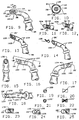
- An aortic cannula is indicated generally as 20 in Fig. 1.
- the coronary cannula 20 comprises a generally tubular sidewall 22 having a proximal end 24 and a distal end 26, with a lumen 28 extending therebetween.
- the cannula tapers toward the distal end so that the distal end has a diameter of between about 6 mm and 8 mm, to fit in the aorta of the patient.
- the distal end 26 of the cannula 20 is closed with an end cap 30.
- the cap 30 may have a rounded, hemispherical shape, as shown in Figs.
- the cap may also have a more conical configuration as shown in Fig. 11, or a rounded beveled configuration resembling a conventional aortic cannula tip, as shown in Fig. 12.
- the rounded shape of the tip also reduces the likelihood of damage to the aorta once the distal end 26 of the cannula 20 is placed in the aorta.
- the cap 30 and the diffuser are preferably molded in one piece with the cannula.
- a tapering diffuser 32 extends from the end cap 30, inside the lumen 28 toward the proximal end 24 of the cannula 20.
- the diffuser 32 tapers toward the proximal end, i.e. , in the upstream direction.
- the diffuser 32 preferably has a conical configuration, and is most preferably frustoconical, with a blunt, rounded apex so that the diffuser does not damage the blood flowing past it.
- the conical diffuser preferably has an apex angle of between about 20° and about 40° to smoothly diffuse the flow and impart a radially outward component to the flow.
- the diffuser 32 could also be pyramidal (or frustopyramidal), with a face of the pyramid oriented toward each of the outlet openings (described below).
- a plurality of outlet openings 34 are formed in the sidewall of the cannula 20, adjacent the distal end 26. These openings 34 preferably have an arched configuration, with the curved portion 36 of each arch oriented toward the proximal end 24, i.e. , oriented in the upstream direction. There are preferably six openings 34, equally spaced around the circumference of the distal end 26 of the cannula 20 (Figs. 2-6). However, there could be three (Figs. 7 and 8) or four (Figs. 9 and 10) or some other suitable number of openings 34. The total area of the openings 34 is preferably greater than the area of the distal end opening in a conventional aortic cannula of the same diameter.
- the length of the openings 34 is preferably slightly greater than the length of the diffuser 32, so that the openings extend further upstream on the sidewall 22 than the diffuser projects in the lumen 28.
- the cross-sectional area of the lumen 28 taken up by the diffuser 32 is made up by the openings 34 so that in effect the diffuser causes no decrease in the cross-sectional area available for flow.
- the diffuser does not interfere with flow or deleteriously increase back pressure; the diffuser merely redirects the flow.
- the diffuser 32 imparts a radially outward component to the flow.
- the diffused flow is thus urged out through the openings 34, with a reduced velocity, because of the greater area of the openings 34, and a generally diffused state because of the diffuser 32 and the radially outward orientation of the openings 34.
- the smooth, continuous shape of the diffuser 32, the blunt, rounded configuration of the end of the diffuser, and the rounded configuration of the openings 34 all help to reduce turbulence in the blood flow and reduce hemolysis.
- the corners and edges in the cannula 20 are preferably rounded to minimize turbulence, and promote a smooth, diffused flow while minimizing the increase in back pressure.
- Deflectors 38 can be formed at the base 40 of each of the openings 34, opposite from the arched portions 36 of the openings.
- the deflectors 38 are preferably in the form of indentations in the cap 30 which further deflect the diffused flow radially outwardly.
- the deflectors have the shape of a portion of a sphere.
- the deflectors 38 splay out the flow, forming an "umbrella" pattern that establishes a stable flow in the aorta, reducing high velocity jetting and evening the flow velocity across the diameter of the aorta.
- FIG. 13-18 An embodiment of an aortic cannula constructed according to the principles of this invention is indicated generally as 20' in Figs. 13-18.
- the cannula 20' is similar to cannula 20, and corresponding reference numerals indicate corresponding parts throughout the several views of the drawings.
- the aortic cannula 20' comprises a sidewall 22, with a proximal end 24 and a distal end 26', and a lumen 28 extending therebetween.
- the distal end 26' of the cannula 20' has a diffuser 100 therein.
- the diffuser 100 has a helical configuration, as shown best in Figs. 18 and 20.
- the diffuser 100 functions to slow the flow through the distal end 26' of the cannula 20', and to diffuse the direction of the flow.
- the diffuser 100 can be held in place by the tapering configuration of the distal end of the cannula 20', by adhesives, by ultrasonic welding, or by some other suitable means.
- the sidewall of the cannula 20' surrounding the diffuser 100 has a plurality of outlet openings 102 therein to permit flow of blood from the cannula.
- the outlet openings 102 prevent a large back pressure from developing because of the diffuser 100 which partially blocks the outlet of the cannula.
- the outlet openings 102 also help maintain a satisfactory flow rate from the cannula. It is desirable that the openings be as large as possible, yet still fit between the splines on the diffuser, so that the openings do not form jets and to minimize hemolysis.
- the diffuser 100 is preferably formed from a flat rectangular member with a single 180° twist therein, to give the diffuser a generally helical configuration.
- the diffuser 100 thus has two oppositely facing splines, formed by the edges of the member.
- the diffuser 100' shown in Figs. 21 and 22, the diffuser has a more complex helical shape, with more splines.
- Additional outlet openings 104 may be provided upstream of the openings 102 to further reduce the back pressure and increase the flow.
- FIG. 23-25 An alternate construction of the distal end 26'' of the cannula 20' of the embodiment is shown on Figs. 23-25.
- the distal end 26'' has a blunt, rounded configuration.
- the distal end has arcuate slots 106 and 108 extending diagonally through the sidewall of the cannula, on opposite sides.
- the concave shape of slot 106 faces distally, the concave shape of slot 108 faces proximal.
- an opening is made into the aorta and the distal end of the cannula 20 or 20' is inserted into the aorta.
- the rounded configuration of cap 30 facilitates the insertion of cannula 20 into the aorta.
- the beveled configuration of the distal end of cannula 20' facilitates the insertion of the cannula in to the aorta.
- the blood encounters the blunt conical diffuser 32 which, by virtue of its low cone angle, gently redirects the flow radially outwardly, through the openings 34.
- the cannula 20 provides a diffused flow that more quickly establishes a stable, more uniform velocity blood flow in the aorta.
- the cannula 20 preferably has deflectors 38 at the base of the openings that further deflect the flow radially outwardly. The flow properties of the blood are such that the deflectors create an "umbrella" flow pattern that more quickly establishes a uniform flow in the aorta.
- the diffuser 100 slows flow through the axial opening in the distal end of the cannula, forcing flow radially outwardly through the outlet openings 102 and 104.
- the axial jetting is eliminated and blood fills the aorta through the openings 102 and 104 in the sidewall 22.
- Fig. 26 shows the flow velocities across the diameter of the aorta, measured 12 mm from the tip of a conventional aortic cannula, 12 mm from the tip of an aortic cannula 20, and 12 mm from the tip of an aortic cannula 20' of the invention.
- Fig. 26 shows that the flow velocities generated by a conventional cannula 12 mm from the tip are as high as 200 cm/sec, and vary considerably across the diameter of the aorta.
- the maximum flow velocity 12 mm from the tip is about 130 cm/sec, and the variation in the velocity across the diameter of the aorta is significantly reduced.
- the maximum flow velocity 12 mm from the tip is about 100 cm/sec, and the variation in the velocity across the diameter of the aorta is also significantly reduced.
- Fig. 27 illustrates the reduction in flow force achieved by the cannulas 20 and 20'.
- Fig. 27 shows the flow force measured 12 mm from the tip of two conventional cannulas as about 0.072 kg (0.16 pounds) and 0.05 kg (0.11 pounds), respectively. However the flow force measured 12 mm from the tip of cannula 0.014 kg (0.03 pounds), as is the flow force measured 12 mm from the tip of cannula 20'.
- the cannula 20' of this invention thus reduces the maximum flow velocity, the variation in flow velocity, and the maximum flow force, while maintaining the overall flow rate. These reductions are believed to be significant in the reduction of thrombo-atheroembolisms, and other possible complications of heart surgery.
Landscapes
- Health & Medical Sciences (AREA)
- Life Sciences & Earth Sciences (AREA)
- Heart & Thoracic Surgery (AREA)
- Hematology (AREA)
- Public Health (AREA)
- Anesthesiology (AREA)
- Biomedical Technology (AREA)
- Engineering & Computer Science (AREA)
- Veterinary Medicine (AREA)
- Animal Behavior & Ethology (AREA)
- General Health & Medical Sciences (AREA)
- Pulmonology (AREA)
- Biophysics (AREA)
- Vascular Medicine (AREA)
- Cardiology (AREA)
- External Artificial Organs (AREA)
- Media Introduction/Drainage Providing Device (AREA)
- Infusion, Injection, And Reservoir Apparatuses (AREA)
- Prostheses (AREA)
Claims (16)
- Canule aortique (20') destinée à être insérée dans l'aorte au cours d'une intervention de chirurgie cardiaque afin de délivrer du sang dans l'aorte, la canule comprenant une paroi latérale (22) ayant une extrémite proximale (24) et une extrémité distale (26') et une lumière (28) disposée à travers celle-ci, un diffuseur (100 ; 100') situé à l'intérieur de la lumière de manière adjacente à l'extrémité distale, le diffuseur présentant une pluralité de cannelures hélicoïdales ménagées sur celui-ci, et des ouvertures d'évacuation (102) dans la partie de la paroi latérale de la canule entourant le diffuseur entre les cannelures ménagées sur le diffuseur.
- Canule aortique selon la revendication 1, dans laquelle le diffuseur (100 ; 100') bloque au moins partiellement l'ouverture distale de la lumière.
- Canule aortique selon la revendication 1 ou 2, comprenant en outre une calotte (30) destinée à bloquer l'écoulement axial depuis l'extremité distale de la canule, et dans laquelle le diffuseur s'étend globalement en amont dans la lumière vers l'extrémité proximale de la canule, et s'effile dans la direction amont et dans laquelle il existe au moins deux ouvertures d'évacuation (102 ; 104) dans la paroi latérale de la canule.
- Canule aortique selon l'une quelconque des revendications 1 à 3, dans laquelle le diffuseur (32 ; 100) a une forme globalement conique avec une pointe émoussée.
- Canule aortique selon l'une quelconque des revendications 1 à 4, dans laquelle les ouvertures d'evacuation (34 ; 102, 104) comprennent des fentes (106, 108) dans la paroi latérale de la canule, de manière adjacente a l'extrémité distale.
- Canule selon la revendication 5, dans laquelle les extrémités proximales des fentes sont arrondies.
- Canule aortique selon la revendication 5 ou 6, dans laquelle les fentes s'étendent de manière proximale au-delà de l'extrémité proximale du diffuseur.
- Canule aortique selon l'une quelconque des revendications 1 à 7, dans lequel il existe trois, quatre ou six ouvertures d'évacuation (34 ; 102, 104) dans la paroi latérale.
- Canule aortique selon l'une quelconque des revendications 1 à 8, comprenant en outre un déflecteur (38) à la base (40) de chaque ouverture d'évacuation (34) destiné à dévier, radialement vers l'extérieur, au moins une partie de l'écoulement issu de chaque ouverture.
- Canule aortique selon l'une quelconque des revendications 3 à 9, dans laquelle le déflecteur comprend une échancrure dans la calotte.
- Canule aortique selon la revendication 10, dans laquelle l'échancrure se présente sous la forme d'une partie de sphère.
- Canule aortique selon l'une quelconque des revendications 1 a 11, dans laquelle les ouvertures sont globalement circulaires.
- Canule aortique selon l'une quelconque des revendications 3 à 12, dans laquelle l'extrémité distale de la calotte (30) présente une forme arrondie hémisphérique.
- Canule aortique selon l'une quelconque des revendications 3 à 12, dans laquelle l'extrémité distale de la calotte (30a) présente une forme arrondie conique.
- Canule aortique selonl'une quelconque des revendications 3 à 12, dans laquelle l'extrémité distale de la calotte (30b) a une extrémité arrondie biseautée.
- Canule aortique selon l'une quelconque des revendications 1 à 15, destinée à être utilisée dans un procédé constituant à délivrer du sang dans l'aorte d'un patient.
Priority Applications (1)
| Application Number | Priority Date | Filing Date | Title |
|---|---|---|---|
| EP99110619A EP0943355A3 (fr) | 1993-02-24 | 1994-02-24 | Canule aortique présentant une faible vitesse d'écoulement |
Applications Claiming Priority (2)
| Application Number | Priority Date | Filing Date | Title |
|---|---|---|---|
| US21811 | 1987-03-13 | ||
| US08/021,811 US5354288A (en) | 1993-02-24 | 1993-02-24 | Low velocity aortic cannula |
Related Child Applications (1)
| Application Number | Title | Priority Date | Filing Date |
|---|---|---|---|
| EP99110619A Division EP0943355A3 (fr) | 1993-02-24 | 1994-02-24 | Canule aortique présentant une faible vitesse d'écoulement |
Publications (2)
| Publication Number | Publication Date |
|---|---|
| EP0612536A1 EP0612536A1 (fr) | 1994-08-31 |
| EP0612536B1 true EP0612536B1 (fr) | 1999-12-29 |
Family
ID=21806284
Family Applications (2)
| Application Number | Title | Priority Date | Filing Date |
|---|---|---|---|
| EP99110619A Withdrawn EP0943355A3 (fr) | 1993-02-24 | 1994-02-24 | Canule aortique présentant une faible vitesse d'écoulement |
| EP94102804A Expired - Lifetime EP0612536B1 (fr) | 1993-02-24 | 1994-02-24 | Canule aortique présentant une faible vitesse d'écoulement |
Family Applications Before (1)
| Application Number | Title | Priority Date | Filing Date |
|---|---|---|---|
| EP99110619A Withdrawn EP0943355A3 (fr) | 1993-02-24 | 1994-02-24 | Canule aortique présentant une faible vitesse d'écoulement |
Country Status (5)
| Country | Link |
|---|---|
| US (2) | US5354288A (fr) |
| EP (2) | EP0943355A3 (fr) |
| JP (1) | JP3529822B2 (fr) |
| CA (1) | CA2115895A1 (fr) |
| DE (1) | DE69422316T2 (fr) |
Cited By (5)
| Publication number | Priority date | Publication date | Assignee | Title |
|---|---|---|---|---|
| US7473245B2 (en) | 2003-01-30 | 2009-01-06 | Sorin Group Deutschland Gmbh | Aortic cannula |
| US8226704B2 (en) | 2003-03-18 | 2012-07-24 | Veryan Medical Limited | Helical stent |
| US9572694B2 (en) | 2003-03-18 | 2017-02-21 | Veryan Medical Limited | Helical graft |
| US9597214B2 (en) | 2008-10-10 | 2017-03-21 | Kevin Heraty | Medical device |
| US10188532B2 (en) | 1998-12-29 | 2019-01-29 | Vascular Flow Technologies Limited | Blood-flow tubing |
Families Citing this family (67)
| Publication number | Priority date | Publication date | Assignee | Title |
|---|---|---|---|---|
| US5643226A (en) * | 1993-02-24 | 1997-07-01 | Minnesota Mining And Manufacturing | Low velocity aortic cannula |
| US5354288A (en) * | 1993-02-24 | 1994-10-11 | Minnesota Mining And Manufacturing Company | Low velocity aortic cannula |
| GB9425493D0 (en) * | 1994-12-16 | 1995-02-15 | Imperial College | Modified cannula |
| GB2310804B (en) * | 1994-12-16 | 1998-09-09 | Imperial College | Modified cannula |
| US5616137A (en) * | 1995-02-22 | 1997-04-01 | Minnesota Mining And Manufacturing Company | Low velocity aortic cannula |
| US5989281A (en) * | 1995-11-07 | 1999-11-23 | Embol-X, Inc. | Cannula with associated filter and methods of use during cardiac surgery |
| US5868703A (en) * | 1996-04-10 | 1999-02-09 | Endoscopic Technologies, Inc. | Multichannel catheter |
| US6821265B1 (en) | 1996-04-10 | 2004-11-23 | Endoscopic Technologies, Inc. | Multichannel catheter |
| AU1525797A (en) * | 1996-04-22 | 1997-11-12 | Medtronic, Inc. | Two-stage angled venous cannula |
| CA2254831C (fr) * | 1996-05-14 | 2006-10-17 | Edwards Lifesciences Corporation | Dispositif d'occlusion aortique a filtre associe et son procede d'utilisation au cours d'une intervention chirurgicale |
| US6048331A (en) * | 1996-05-14 | 2000-04-11 | Embol-X, Inc. | Cardioplegia occluder |
| JPH11114069A (ja) * | 1997-10-14 | 1999-04-27 | Junichi Tanaka | カテーテル |
| JPH10137341A (ja) * | 1996-11-12 | 1998-05-26 | Junichi Tanaka | カテーテル |
| US6387087B1 (en) | 1996-12-11 | 2002-05-14 | Ronald K. Grooters | Aortic cannula |
| US6524296B1 (en) * | 1997-04-17 | 2003-02-25 | Medtronic, Inc. | Vessel cannula having properties varying along the axial length |
| US6217546B1 (en) | 1997-05-19 | 2001-04-17 | United States Surgical Corporation | Catheter system |
| US6099506A (en) | 1997-09-26 | 2000-08-08 | Macoviak; John A. | Introducer and perfusion cannula |
| US6254578B1 (en) * | 1997-09-30 | 2001-07-03 | Ronald K. Grooters | Aortic cannula with tapered tip |
| US5876383A (en) * | 1997-09-30 | 1999-03-02 | Grooters; Robert K. | Cannula |
| US6186987B1 (en) | 1997-09-30 | 2001-02-13 | Ronald K. Grooters | Aortic cannula with spoon-shaped lip |
| US6179827B1 (en) | 1998-03-16 | 2001-01-30 | Chase Medical | Catheter having integral expandable/collapsible lumen |
| US5976114A (en) * | 1998-04-30 | 1999-11-02 | Medtronic, Inc. | Aortic cannula with reduced velocity flow-through tip |
| US6508777B1 (en) | 1998-05-08 | 2003-01-21 | Cardeon Corporation | Circulatory support system and method of use for isolated segmental perfusion |
| US6726651B1 (en) | 1999-08-04 | 2004-04-27 | Cardeon Corporation | Method and apparatus for differentially perfusing a patient during cardiopulmonary bypass |
| US6245007B1 (en) | 1999-01-28 | 2001-06-12 | Terumo Cardiovascular Systems Corporation | Blood pump |
| DE19904896A1 (de) * | 1999-02-06 | 2000-08-10 | Convergenza Ag Vaduz | Kanüle |
| US6210363B1 (en) | 1999-02-23 | 2001-04-03 | Cardeon Corporation | Methods and devices for occluding a vessel and performing differential perfusion |
| CA2311977A1 (fr) | 1999-06-18 | 2000-12-18 | Helmut Reul | Methode d'administration d'un fluide dans un vaisseau d'un organisme humain, et canule amelioree utile a l'execution de la methode |
| DE19933171A1 (de) * | 1999-06-18 | 2000-12-21 | Medos Medizintechnik Gmbh | Verfahren zum Einbringen eines Fluides in ein Gefäß des menschlichen Körpers sowie entsprechende Kanüle |
| US6750056B2 (en) * | 2001-09-06 | 2004-06-15 | Roger A. Acey | Metal binding proteins and associated methods |
| WO2001034239A2 (fr) | 1999-11-09 | 2001-05-17 | Grooters Ronald K | Canule aortique amelioree pourvue d'une levre en forme de cuillere |
| US6224581B1 (en) * | 1999-11-24 | 2001-05-01 | Ginette Withers | Ostomy bag cleaning appliance having a mounting plate |
| JP2001161805A (ja) * | 1999-12-10 | 2001-06-19 | Hideo Takehara | 留置l型カテーテル |
| EP1127557A1 (fr) * | 2000-02-25 | 2001-08-29 | EndoArt S.A. | Greffe vasculaire |
| EP1374799A1 (fr) * | 2002-06-18 | 2004-01-02 | F.R.I.D. R&D Benelux Sprl | Endoprothèse luminale hémodynamique |
| US6802806B2 (en) | 2002-09-23 | 2004-10-12 | Cleveland Clinic Foundation | Apparatus for use with an inflow cannula of ventricular assist device |
| US20040210202A1 (en) * | 2003-04-17 | 2004-10-21 | Weinstein Gerald S. | Aortic cannula |
| US20040267212A1 (en) * | 2003-06-27 | 2004-12-30 | Jonkman Kenneth R. | Diverging tip aortic cannula |
| US20050197644A1 (en) * | 2004-03-03 | 2005-09-08 | Waychoff Challen W.Ii | Colon hydrotherapy device |
| US8323227B2 (en) | 2004-07-02 | 2012-12-04 | C. R. Bard, Inc. | Tip configurations for a multi-lumen catheter |
| US20060004316A1 (en) | 2004-07-02 | 2006-01-05 | Difiore Attilio E | Reduction of recirculation in catheters |
| US7824358B2 (en) * | 2004-07-22 | 2010-11-02 | Thoratec Corporation | Heart pump connector |
| US7479126B1 (en) * | 2004-10-29 | 2009-01-20 | Endoscopic Technologies, Inc. | Cannula with incision blade |
| US20060253059A1 (en) * | 2005-04-21 | 2006-11-09 | Edwards Lifesciences, Llc | Soft-flow aortic cannula tip |
| GB0509583D0 (en) * | 2005-05-11 | 2005-06-15 | Univ Wolverhampton The | Biomechanical probe |
| WO2010039607A2 (fr) * | 2008-10-01 | 2010-04-08 | Zarate Alfredo R | Méthodes permettant d’améliorer la distribution de fluide |
| KR101537523B1 (ko) * | 2008-07-16 | 2015-07-17 | 하트웨어, 인코포레이티드 | 심실보조장치와 함께 사용하기 위한 캐뉼러 팁 |
| US8603049B2 (en) * | 2008-12-15 | 2013-12-10 | Kimberly-Clark Worldwide, Inc. | Atraumatic suction catheter |
| JP5345408B2 (ja) * | 2009-01-22 | 2013-11-20 | 泉工医科工業株式会社 | カニューレ |
| KR20120087964A (ko) * | 2009-10-29 | 2012-08-07 | 로버트 이. 헬름 | 밀봉된 무균 카테터 드레싱 |
| US10682507B2 (en) | 2009-10-29 | 2020-06-16 | One Iv Solutions, Llc | Catheter extension with integrated circumferentially sealing securement dressing |
| WO2012106088A2 (fr) | 2011-01-31 | 2012-08-09 | Helm Robert E Jr | Système cathéter-pansement intravasculaire stérile, à jonction étanche instantanée |
| DE102011016311A1 (de) | 2011-04-07 | 2012-10-11 | Sebastian Stühle | Aortenkanülle mit verbessertem Ausströmverhalten |
| WO2013040154A1 (fr) | 2011-09-15 | 2013-03-21 | Helm Robert E Jr | Systèmes de pansements pour cathéter comprenant des mécanismes de rinçage intégrés |
| US9616214B2 (en) * | 2012-05-21 | 2017-04-11 | Becton, Dickinson And Company | Flush enhancing male luer tip design for syringes and any luer connector |
| WO2013181169A1 (fr) | 2012-06-01 | 2013-12-05 | Carnegie Mellon University | Pointe de canule pour une canule artérielle |
| ES2736317T3 (es) | 2012-08-03 | 2019-12-27 | Nat Univ Singapore | Cánula arterial que permite la perfusión a lo largo de direcciones opuestas dentro de un vaso canulado |
| US9155862B2 (en) * | 2012-09-28 | 2015-10-13 | Covidien Lp | Symmetrical tip acute catheter |
| WO2014134624A1 (fr) * | 2013-03-01 | 2014-09-04 | The Arizona Board Of Regents On Behalf Of The University Of Arizona | Aiguille de veress modifiée pour la décompression d'un pneumothorax sous tension |
| DE102015005002A1 (de) | 2015-04-21 | 2016-10-27 | Xenios Ag | Kanüle |
| JP6876710B2 (ja) * | 2016-09-14 | 2021-05-26 | テルモ株式会社 | カテーテル |
| WO2018085706A1 (fr) | 2016-11-04 | 2018-05-11 | The Arizona Board Of Regents On Behalf Of The University Of Arizona | Ensemble aiguille de veress modifiée pour décompression de pneumothorax sous pression |
| JP6788792B2 (ja) * | 2016-11-17 | 2020-11-25 | ニプロ株式会社 | カニューレ |
| ES3015192T3 (en) * | 2019-12-31 | 2025-04-30 | Abiomed Inc | Blood pump distal outflow cage |
| USD1092716S1 (en) | 2019-12-31 | 2025-09-09 | Abiomed, Inc. | Outflow cage for blood pump |
| WO2021257347A1 (fr) * | 2020-06-17 | 2021-12-23 | Tc1 Llc | Ensemble pompe à sang extracorporel et ses procédés d'assemblage |
| CN117045931A (zh) * | 2023-07-14 | 2023-11-14 | 深圳核心医疗科技股份有限公司 | 送液管、套管组件及血泵 |
Family Cites Families (47)
| Publication number | Priority date | Publication date | Assignee | Title |
|---|---|---|---|---|
| US609280A (en) * | 1898-08-16 | Ferdinand king | ||
| US611454A (en) * | 1898-09-27 | Charles e | ||
| US275405A (en) * | 1883-04-10 | Instrument for treating the vagina and uterus | ||
| US829952A (en) * | 1905-10-14 | 1906-09-04 | Walter M Dean | Syringe. |
| US2393728A (en) * | 1941-11-24 | 1946-01-29 | Aguiar Clovis De Paiva | Nozzle for duodenal pump tubes |
| US2356659A (en) * | 1941-11-24 | 1944-08-22 | Aguiar Clovis De Paiva | Nozzle for duodenal pump tubes |
| US2862498A (en) * | 1957-06-14 | 1958-12-02 | Don J Weekes | Endotracheal tube |
| US2854983A (en) * | 1957-10-31 | 1958-10-07 | Arnold M Baskin | Inflatable catheter |
| US3108595A (en) * | 1960-08-08 | 1963-10-29 | Alfred P Overment | Retention catheter |
| US3397699A (en) * | 1966-05-05 | 1968-08-20 | Gerald C. Kohl | Retaining catheter having resiliently biased wing flanges |
| GB1269405A (en) | 1968-06-28 | 1972-04-06 | Sherwood Medical Ind Inc | Cardiac catheter |
| US3568659A (en) * | 1968-09-24 | 1971-03-09 | James N Karnegis | Disposable percutaneous intracardiac pump and method of pumping blood |
| US3605750A (en) * | 1969-04-07 | 1971-09-20 | David S Sheridan | X-ray tip catheter |
| US3799172A (en) * | 1972-09-25 | 1974-03-26 | R Szpur | Retention catheter |
| US3955573A (en) * | 1974-10-11 | 1976-05-11 | Sorenson Research Co., Inc. | Anticoagulant delivery device and method |
| US3938530A (en) * | 1974-11-15 | 1976-02-17 | Santomieri Louis | Catheter |
| US3964484A (en) * | 1975-03-03 | 1976-06-22 | Sorenson Research Co., Inc. | Antiocoagulant metering device and method |
| US4297115A (en) * | 1979-09-18 | 1981-10-27 | Staclean Diffuser Company | Bag-type filter with air diffuser tubes of helical construction |
| IT1119233B (it) * | 1979-10-17 | 1986-03-03 | Michele Labianca | Perfezionamenti nei cateteri per sistemi di derivazione del fluido cerebrospinale per idrocefalia |
| US4321920A (en) * | 1980-06-03 | 1982-03-30 | Gillig H E | Peristalsis stimulating device |
| US4437856A (en) * | 1981-02-09 | 1984-03-20 | Alberto Valli | Peritoneal catheter device for dialysis |
| SE433445B (sv) * | 1981-04-16 | 1984-05-28 | Erik Gustav Percy Nordqvist | Urinkateter |
| US4522195A (en) * | 1981-05-25 | 1985-06-11 | Peter Schiff | Apparatus for left heart assist |
| WO1983003204A1 (fr) * | 1982-03-12 | 1983-09-29 | Webster, Wilton, W., Jr. | Catheter auto-gonflable |
| US4474206A (en) * | 1982-04-05 | 1984-10-02 | Imed Corporation | Apparatus for, and method of, controlling the flow of fluid |
| US4693243A (en) * | 1983-01-14 | 1987-09-15 | Buras Sharon Y | Conduit system for directly administering topical anaesthesia to blocked laryngeal-tracheal areas |
| US4680029A (en) * | 1984-02-23 | 1987-07-14 | Sherwood Medical Company | Vena caval catheter |
| US4801297A (en) * | 1984-06-01 | 1989-01-31 | Edward Weck Incorporated | Catheter having slit tip |
| US4617019A (en) * | 1984-09-28 | 1986-10-14 | Sherwood Medical Company | Catheter |
| US4580568A (en) * | 1984-10-01 | 1986-04-08 | Cook, Incorporated | Percutaneous endovascular stent and method for insertion thereof |
| US4596548A (en) * | 1985-03-25 | 1986-06-24 | Dlp Inc. | Single stage venous catheter |
| US4655745A (en) * | 1985-07-29 | 1987-04-07 | Corbett Joseph E | Ventricular catheter |
| GB2181650B (en) * | 1985-10-18 | 1989-09-13 | Blagoveshchensk G Med Inst | Aortic cannula |
| SE449053B (sv) * | 1986-01-16 | 1987-04-06 | Gambro Cardio Ab | Hjertkateter |
| US4795446A (en) * | 1986-01-30 | 1989-01-03 | Sherwood Medical Company | Medical tube device |
| US4795439A (en) * | 1986-06-06 | 1989-01-03 | Edward Weck Incorporated | Spiral multi-lumen catheter |
| US4710180A (en) * | 1986-10-06 | 1987-12-01 | Johnson Gerald W | Lipoject needle |
| US4863441A (en) * | 1987-07-17 | 1989-09-05 | Minnesota Mining And Manufacturing Company | Venous return catheter |
| US4813935A (en) * | 1987-07-27 | 1989-03-21 | Habley Medical Technology Corporation | Urinary catheter |
| US4802819A (en) * | 1987-09-14 | 1989-02-07 | Mcneil (Ohio) Corporation | Centrifugal pump |
| US4921478A (en) * | 1988-02-23 | 1990-05-01 | C. R. Bard, Inc. | Cerebral balloon angioplasty system |
| US4966585A (en) * | 1988-05-31 | 1990-10-30 | Gangemi Ronald J | Infusion apparatus |
| US5021044A (en) * | 1989-01-30 | 1991-06-04 | Advanced Cardiovascular Systems, Inc. | Catheter for even distribution of therapeutic fluids |
| US5084033A (en) * | 1990-03-12 | 1992-01-28 | Minnesota Mining And Manufacturing Company | Arterial cannula tip and method of manufacture |
| US5147332A (en) * | 1991-05-17 | 1992-09-15 | C.R. Bard, Inc. | Multi-valve catheter for improved reliability |
| US5300022A (en) * | 1992-11-12 | 1994-04-05 | Martin Klapper | Urinary catheter and bladder irrigation system |
| US5354288A (en) * | 1993-02-24 | 1994-10-11 | Minnesota Mining And Manufacturing Company | Low velocity aortic cannula |
-
1993
- 1993-02-24 US US08/021,811 patent/US5354288A/en not_active Expired - Lifetime
-
1994
- 1994-02-17 CA CA002115895A patent/CA2115895A1/fr not_active Abandoned
- 1994-02-24 DE DE69422316T patent/DE69422316T2/de not_active Expired - Lifetime
- 1994-02-24 JP JP02688794A patent/JP3529822B2/ja not_active Expired - Lifetime
- 1994-02-24 EP EP99110619A patent/EP0943355A3/fr not_active Withdrawn
- 1994-02-24 EP EP94102804A patent/EP0612536B1/fr not_active Expired - Lifetime
- 1994-10-07 US US08/318,207 patent/US5685865A/en not_active Expired - Lifetime
Cited By (7)
| Publication number | Priority date | Publication date | Assignee | Title |
|---|---|---|---|---|
| US10188532B2 (en) | 1998-12-29 | 2019-01-29 | Vascular Flow Technologies Limited | Blood-flow tubing |
| US7473245B2 (en) | 2003-01-30 | 2009-01-06 | Sorin Group Deutschland Gmbh | Aortic cannula |
| US8226704B2 (en) | 2003-03-18 | 2012-07-24 | Veryan Medical Limited | Helical stent |
| US8784476B2 (en) | 2003-03-18 | 2014-07-22 | Veryan Medical Limited | Helical stent |
| US9572694B2 (en) | 2003-03-18 | 2017-02-21 | Veryan Medical Limited | Helical graft |
| US9597214B2 (en) | 2008-10-10 | 2017-03-21 | Kevin Heraty | Medical device |
| US9883961B2 (en) | 2008-10-10 | 2018-02-06 | Veryan Medical Limited | Medical device |
Also Published As
| Publication number | Publication date |
|---|---|
| DE69422316D1 (de) | 2000-02-03 |
| EP0612536A1 (fr) | 1994-08-31 |
| DE69422316T2 (de) | 2001-04-26 |
| JPH0767965A (ja) | 1995-03-14 |
| EP0943355A2 (fr) | 1999-09-22 |
| US5354288A (en) | 1994-10-11 |
| US5685865A (en) | 1997-11-11 |
| EP0943355A3 (fr) | 1999-10-27 |
| CA2115895A1 (fr) | 1994-08-25 |
| JP3529822B2 (ja) | 2004-05-24 |
Similar Documents
| Publication | Publication Date | Title |
|---|---|---|
| US5354288A (en) | Low velocity aortic cannula | |
| US5643226A (en) | Low velocity aortic cannula | |
| US5616137A (en) | Low velocity aortic cannula | |
| US5662619A (en) | Venous dialysis needle | |
| JP4244800B2 (ja) | 経皮冠動脈介入および末梢神経介入において用いられる抹消神経保護性ダブルルーメン・カテーテル | |
| DE69500959T2 (de) | Mechanische vorrichtung zum fragmentieren von thromben | |
| US5876383A (en) | Cannula | |
| US5147334A (en) | Catheter for cholangiography | |
| DE69221621T2 (de) | Selbstzentrierende mechanische, medizinische vorrichtung | |
| US6387087B1 (en) | Aortic cannula | |
| EP1383569B1 (fr) | Canule pourvue d'un mecanisme de deviation d'ecoulement | |
| US5496344A (en) | Dilator for a ballon catheter | |
| US6186987B1 (en) | Aortic cannula with spoon-shaped lip | |
| AU2002305100B2 (en) | Medical instrument with an atraumatic end | |
| US20020193822A1 (en) | Externally positioned medical dilator | |
| EP1871452B1 (fr) | Pointe de canule aortique haute fluidite | |
| EP1227857B1 (fr) | Canule aortique pourvue d'une levre en forme de cuillere | |
| US20260114888A1 (en) | Thrombectomy system and method of removing thrombus | |
| US7479126B1 (en) | Cannula with incision blade |
Legal Events
| Date | Code | Title | Description |
|---|---|---|---|
| PUAI | Public reference made under article 153(3) epc to a published international application that has entered the european phase |
Free format text: ORIGINAL CODE: 0009012 |
|
| AK | Designated contracting states |
Kind code of ref document: A1 Designated state(s): DE FR GB |
|
| 17P | Request for examination filed |
Effective date: 19950215 |
|
| 17Q | First examination report despatched |
Effective date: 19950914 |
|
| GRAG | Despatch of communication of intention to grant |
Free format text: ORIGINAL CODE: EPIDOS AGRA |
|
| GRAG | Despatch of communication of intention to grant |
Free format text: ORIGINAL CODE: EPIDOS AGRA |
|
| GRAG | Despatch of communication of intention to grant |
Free format text: ORIGINAL CODE: EPIDOS AGRA |
|
| GRAH | Despatch of communication of intention to grant a patent |
Free format text: ORIGINAL CODE: EPIDOS IGRA |
|
| GRAH | Despatch of communication of intention to grant a patent |
Free format text: ORIGINAL CODE: EPIDOS IGRA |
|
| GRAA | (expected) grant |
Free format text: ORIGINAL CODE: 0009210 |
|
| AK | Designated contracting states |
Kind code of ref document: B1 Designated state(s): DE FR GB |
|
| REF | Corresponds to: |
Ref document number: 69422316 Country of ref document: DE Date of ref document: 20000203 |
|
| ET | Fr: translation filed | ||
| RAP2 | Party data changed (patent owner data changed or rights of a patent transferred) |
Owner name: THE CLEVELAND CLINIC FOUNDATION Owner name: TERUMO CARDIOVASCULAR SYSTEMS CORPORATION |
|
| PLBE | No opposition filed within time limit |
Free format text: ORIGINAL CODE: 0009261 |
|
| STAA | Information on the status of an ep patent application or granted ep patent |
Free format text: STATUS: NO OPPOSITION FILED WITHIN TIME LIMIT |
|
| 26N | No opposition filed | ||
| REG | Reference to a national code |
Ref country code: GB Ref legal event code: IF02 |
|
| PGFP | Annual fee paid to national office [announced via postgrant information from national office to epo] |
Ref country code: FR Payment date: 20120203 Year of fee payment: 19 |
|
| PGFP | Annual fee paid to national office [announced via postgrant information from national office to epo] |
Ref country code: DE Payment date: 20120229 Year of fee payment: 19 |
|
| PGFP | Annual fee paid to national office [announced via postgrant information from national office to epo] |
Ref country code: GB Payment date: 20120127 Year of fee payment: 19 |
|
| GBPC | Gb: european patent ceased through non-payment of renewal fee |
Effective date: 20130224 |
|
| REG | Reference to a national code |
Ref country code: FR Ref legal event code: ST Effective date: 20131031 |
|
| REG | Reference to a national code |
Ref country code: DE Ref legal event code: R119 Ref document number: 69422316 Country of ref document: DE Effective date: 20130903 |
|
| PG25 | Lapsed in a contracting state [announced via postgrant information from national office to epo] |
Ref country code: FR Free format text: LAPSE BECAUSE OF NON-PAYMENT OF DUE FEES Effective date: 20130228 Ref country code: GB Free format text: LAPSE BECAUSE OF NON-PAYMENT OF DUE FEES Effective date: 20130224 Ref country code: DE Free format text: LAPSE BECAUSE OF NON-PAYMENT OF DUE FEES Effective date: 20130903 |