EP0612565A1 - Rotor pour centrifugeuse à godets pivotants - Google Patents
Rotor pour centrifugeuse à godets pivotants Download PDFInfo
- Publication number
- EP0612565A1 EP0612565A1 EP94101355A EP94101355A EP0612565A1 EP 0612565 A1 EP0612565 A1 EP 0612565A1 EP 94101355 A EP94101355 A EP 94101355A EP 94101355 A EP94101355 A EP 94101355A EP 0612565 A1 EP0612565 A1 EP 0612565A1
- Authority
- EP
- European Patent Office
- Prior art keywords
- rotor
- leg
- swivel
- swivel cup
- rotor according
- Prior art date
- Legal status (The legal status is an assumption and is not a legal conclusion. Google has not performed a legal analysis and makes no representation as to the accuracy of the status listed.)
- Granted
Links
Images


Classifications
-
- B—PERFORMING OPERATIONS; TRANSPORTING
- B04—CENTRIFUGAL APPARATUS OR MACHINES FOR CARRYING-OUT PHYSICAL OR CHEMICAL PROCESSES
- B04B—CENTRIFUGES
- B04B5/00—Other centrifuges
- B04B5/04—Radial chamber apparatus for separating predominantly liquid mixtures, e.g. butyrometers
- B04B5/0407—Radial chamber apparatus for separating predominantly liquid mixtures, e.g. butyrometers for liquids contained in receptacles
- B04B5/0414—Radial chamber apparatus for separating predominantly liquid mixtures, e.g. butyrometers for liquids contained in receptacles comprising test tubes
- B04B5/0421—Radial chamber apparatus for separating predominantly liquid mixtures, e.g. butyrometers for liquids contained in receptacles comprising test tubes pivotably mounted
Definitions
- the invention relates to a rotor for a swivel cup centrifuge according to the preamble of patent claim 1.
- Such a rotor has become known from DE 89 03 511 U1, which goes back to the same applicant.
- the swivel cups are designed as sample tubes so that they are filled directly with a sample liquid and, moreover, consist of plastic.
- Radially front and rear recesses lying one behind the other in the radial direction are incorporated in the rotor, which is essentially designed as a horizontal disk, and are intended to enable the swivel cup to pivot into these recesses when the swivel cup swings out.
- the known swivel cups When swinging out, the known swivel cups rest with their bottom regions on a circumferential, radially outer flange of the rotor, the handle-like legs serving as swivel bearings, which engage in the associated recesses in the disk, no longer being supposed to have a load-transmitting effect.
- the known rotor therefore had the advantage that relatively inexpensive sample vessels could be used, which could be hooked into the rotor with their handle-like, free legs without any additional aids.
- the invention is therefore based on the object of developing a rotor of the type mentioned in such a way that the rotor itself can be of simple construction and nevertheless high centrifugal forces can be transmitted from the swivel cups to the rotor.
- the invention is characterized by the technical teaching of claim 1.
- the rotor is now essentially in the form of a disk which bears a series of slots distributed in the circumferential direction. There is now no need to provide a load-transmitting, radial, cranked flange on the outer circumference of the rotor, which absorbs the centrifugal force of the swivel cup, as was required in DE 89 03 511 U1.
- the centrifugal force which is exerted on the swivel cups is transmitted directly from the swivel cups to the support part assigned to each swivel cup, which support part essentially consists of an annular metal part which is embedded in the sleeve of the swivel cup, with this ring part - preferably made of one piece of material - at least one leg is formed, with which this carrier part engages through the slot in the rotor and is pivotably mounted there.
- the legs are preferably inclined and are dimensioned (length, width and thickness, as well as angular position to the longitudinal axis of the sleeve of the swivel cup), that in a first preferred embodiment there is an approximate weight compensation for the swivel cup when the target speed of the rotor is reached.
- the length of the leg is chosen so that the free lower end of the leg approximately ends with the bottom region of the sleeve of the swivel cup, so that the swivel cup can be set up freely on an installation level and the leg thus serves as a supporting foot.
- the leg is bent, preferably an approximately Z-shaped shape is preferred, so that the free, bent end of the leg rests on certain stop surfaces of the disk-shaped rotor when the swivel cup swings out.
- the leg is bent so that in the rest position of the hanger, i.e. when the rotor is at a standstill, the free outer end of the leg bears against the rotor head so as to define the pivoting position of the swivel cup when the rotor is at a standstill.
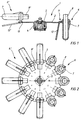
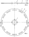
- the rotor 1 according to Figures 1 and 2 consists essentially of a disc 2, which is preferably made of a high-strength, rustproof metal material, for. B. consists of a nickel-chromium alloy.
- the disk 2 is connected via screws 5 to a rotor head 4, which is connected to the drive shaft of a drive motor, not shown, via the fastening means shown.
- the disc 2 is provided with a central recess 3, through which parts of the rotor head 4 pass.
- slots 9 are worked into the disk 2 evenly distributed on the circumference of the rotor, the radially outer edges 10 of the slots 9 preferably being machined, for example having a round profile, around a pivot bearing for the swinging-out carrier parts 11 of the pivot cups 6 form.
- Each swivel cup 6 consists of a sleeve 7, which preferably consists of a plastic material, in the upper, collar-shaped, enlarged edge of which the carrier part 11 is embedded.
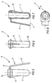
- the carrier part 11 consists of a ring 14 made of a high-strength metal material, on which a part 13 is integrally formed, which merges into a leg 12 bent downwards over a bending edge.
- the parts 12, 13, 14 preferably consist of a material which is integrally connected to one another.
- a rib 15 is formed on the side of the sleeve 7 opposite the leg 12 in order to ensure that the sleeve 7 is stabilized in this area.
- a sample tube 8 is placed, which receives the sample liquid.
- the sleeve 7 is adapted to the sample tube 8.
- the free end of the leg 12 is chosen so long that it forms approximately a line 17 with the bottom region of the sleeve 7, it being possible for a rib 16 to be additionally formed on the bottom region of the sleeve.
- the leg 12 serves as a support foot for the swivel cup 6, which can thus be placed freely on a footprint.
- the swivel cups 6 pivot outwards, as shown in FIG. 1, 2 on the left side.
- the edges 10 of the slots 9 serve as pivot bearings and the swinging out takes place in the transition region between the straight part 13 and the leg 12 of the carrier part 11 bent downwards.
- the carrier part 11 transmits the centrifugal force to the slot 9 via the edge 10 to the disk 2 in a load-transmitting manner.
- the rotor can thus be of the simplest design and no complex contact surfaces on the rotor are required to absorb centrifugal forces.
- FIG. 12 shows a further rotor 20 which holds swivel cups 6 which are connected to differently designed carrier parts 21.
- Each carrier part here has a leg 22 which is bent approximately in a Z-shape and which, in the rest position of the swivel cup 6, rests with its end edge 23 on the rotor head 4. In this way, in the rest position of the rotor, a certain, desired and adjustable by the shape of the legs 22 inclined position of the swivel cup is achieved.
- a swivel position can also be set arbitrarily by shaping the legs 22 when the swivel cup is swung out. In this case, the end edge 23 of the leg 22 then strikes (not shown) on the associated stop surfaces of the rotor.
Landscapes
- Centrifugal Separators (AREA)
Applications Claiming Priority (2)
| Application Number | Priority Date | Filing Date | Title |
|---|---|---|---|
| DE4305581A DE4305581A1 (de) | 1993-02-24 | 1993-02-24 | Rotor für eine Schwenkbecherzentrifuge |
| DE4305581 | 1993-02-24 |
Publications (2)
| Publication Number | Publication Date |
|---|---|
| EP0612565A1 true EP0612565A1 (fr) | 1994-08-31 |
| EP0612565B1 EP0612565B1 (fr) | 1997-04-09 |
Family
ID=6481162
Family Applications (1)
| Application Number | Title | Priority Date | Filing Date |
|---|---|---|---|
| EP94101355A Expired - Lifetime EP0612565B1 (fr) | 1993-02-24 | 1994-01-29 | Rotor pour centrifugeuse à godets pivotants |
Country Status (3)
| Country | Link |
|---|---|
| US (1) | US5456652A (fr) |
| EP (1) | EP0612565B1 (fr) |
| DE (2) | DE4305581A1 (fr) |
Cited By (1)
| Publication number | Priority date | Publication date | Assignee | Title |
|---|---|---|---|---|
| DE102008042971A1 (de) | 2008-10-20 | 2010-04-22 | Agilent Technologies Inc., Santa Clara | Zentrifuge mit Magneteinrichtung |
Families Citing this family (17)
| Publication number | Priority date | Publication date | Assignee | Title |
|---|---|---|---|---|
| US5588946A (en) * | 1994-06-24 | 1996-12-31 | Johnson & Johnson Clinical Diagnostics, Inc. | Centrifuge and phase separation |
| US6001310A (en) * | 1996-10-11 | 1999-12-14 | Shaffer; John V. | Pliable centrifuge tube array |
| WO1999021658A1 (fr) * | 1997-10-27 | 1999-05-06 | Michael Yavilevich | Ensemble de centrifugation combine |
| WO2000047328A1 (fr) * | 1999-02-11 | 2000-08-17 | Seward Limited | Rotor a action centrifugeuse |
| JP4099961B2 (ja) * | 2001-07-19 | 2008-06-11 | 日立工機株式会社 | 遠心分離機用スイングロータ及び遠心分離機 |
| DE10316598B4 (de) * | 2003-04-11 | 2008-05-21 | Andreas Hettich Gmbh & Co. Kg | Verfahren und Zentrifuge zur Gewinnung von biologischen Flüssigkeiten |
| CA3138078C (fr) | 2007-10-02 | 2024-02-13 | Labrador Diagnostics Llc | Dispositifs modulaires a utiliser sur place et leurs utilisations |
| MX349288B (es) | 2011-01-21 | 2017-07-21 | Theranos Inc | Sistemas y metodos para maximizacion de uso de muestras. |
| US9664702B2 (en) | 2011-09-25 | 2017-05-30 | Theranos, Inc. | Fluid handling apparatus and configurations |
| US20140170735A1 (en) | 2011-09-25 | 2014-06-19 | Elizabeth A. Holmes | Systems and methods for multi-analysis |
| US9632102B2 (en) | 2011-09-25 | 2017-04-25 | Theranos, Inc. | Systems and methods for multi-purpose analysis |
| US8475739B2 (en) | 2011-09-25 | 2013-07-02 | Theranos, Inc. | Systems and methods for fluid handling |
| US10012664B2 (en) | 2011-09-25 | 2018-07-03 | Theranos Ip Company, Llc | Systems and methods for fluid and component handling |
| US9810704B2 (en) | 2013-02-18 | 2017-11-07 | Theranos, Inc. | Systems and methods for multi-analysis |
| US11545241B1 (en) | 2013-09-07 | 2023-01-03 | Labrador Diagnostics Llc | Systems and methods for analyte testing and data management |
| CN104056733B (zh) * | 2014-06-10 | 2017-06-13 | 苏州培英实验设备有限公司 | 自闭式按压离心机转盘 |
| JP2017527288A (ja) | 2014-09-04 | 2017-09-21 | セラノス, インコーポレイテッドTheranos, Inc. | 病原体及び抗菌薬耐性試験 |
Citations (8)
| Publication number | Priority date | Publication date | Assignee | Title |
|---|---|---|---|---|
| DE643836C (de) * | 1933-07-13 | 1937-04-17 | Collatz & Co E | Zentrifuge |
| DE894010C (de) * | 1951-03-30 | 1953-10-22 | Paul Funke & Co | Zentrifuge fuer Butyrometer |
| US3420437A (en) * | 1967-02-15 | 1969-01-07 | Sorvall Inc Ivan | Cell washing centrifuge |
| FR2107154A5 (fr) * | 1970-09-08 | 1972-05-05 | Technicon Instr | |
| DE2910868A1 (de) * | 1979-03-20 | 1980-10-09 | Heraeus Christ Gmbh | Zentrifuge fuer zu analysierende probefluessigkeiten |
| EP0088425A2 (fr) * | 1982-03-10 | 1983-09-14 | E.I. Du Pont De Nemours And Company | Appareil de lavage de cellules, comportant des bras de retenue dirigés radialement vers l'intérieur |
| SU1080877A1 (ru) * | 1982-01-14 | 1984-03-23 | Московский технологический институт мясной и молочной промышленности | Центрифуга (ее варианты) |
| DE8903511U1 (de) * | 1989-03-21 | 1990-01-11 | Fa. Andreas Hettich, 7200 Tuttlingen | Zentrifugenrotor mit Einsatzröhrchen |
Family Cites Families (8)
| Publication number | Priority date | Publication date | Assignee | Title |
|---|---|---|---|---|
| US484685A (en) * | 1892-10-18 | Centrifugal milk-tester | ||
| US486390A (en) * | 1892-11-15 | Centrifugal cream-tester | ||
| US3680967A (en) * | 1970-09-14 | 1972-08-01 | Technicon Instr | Self-locating sample receptacle having integral identification label |
| US3781120A (en) * | 1970-09-14 | 1973-12-25 | Technicon Instr | Self-locating sample receptacle having integral identification label |
| US3877634A (en) * | 1973-05-25 | 1975-04-15 | Du Pont | Cell washing centrifuge apparatus and system |
| DE3118367C2 (de) * | 1979-09-21 | 1984-05-24 | Fa. Andreas Hettich, 7200 Tuttlingen | Zentrifugenbecher aus Kunststoffmaterial |
| DE2938317C2 (de) * | 1979-09-21 | 1983-04-28 | Fa. Andreas Hettich, 7200 Tuttlingen | Zentrifugenbecher aus Kunststoffmaterial |
| US4589864A (en) * | 1984-11-05 | 1986-05-20 | E. I. Du Pont De Nemours And Company | Centrifuge rotor having a resilient trunnion |
-
1993
- 1993-02-24 DE DE4305581A patent/DE4305581A1/de not_active Ceased
-
1994
- 1994-01-29 EP EP94101355A patent/EP0612565B1/fr not_active Expired - Lifetime
- 1994-01-29 DE DE59402331T patent/DE59402331D1/de not_active Expired - Lifetime
- 1994-02-22 US US08/200,283 patent/US5456652A/en not_active Expired - Lifetime
Patent Citations (8)
| Publication number | Priority date | Publication date | Assignee | Title |
|---|---|---|---|---|
| DE643836C (de) * | 1933-07-13 | 1937-04-17 | Collatz & Co E | Zentrifuge |
| DE894010C (de) * | 1951-03-30 | 1953-10-22 | Paul Funke & Co | Zentrifuge fuer Butyrometer |
| US3420437A (en) * | 1967-02-15 | 1969-01-07 | Sorvall Inc Ivan | Cell washing centrifuge |
| FR2107154A5 (fr) * | 1970-09-08 | 1972-05-05 | Technicon Instr | |
| DE2910868A1 (de) * | 1979-03-20 | 1980-10-09 | Heraeus Christ Gmbh | Zentrifuge fuer zu analysierende probefluessigkeiten |
| SU1080877A1 (ru) * | 1982-01-14 | 1984-03-23 | Московский технологический институт мясной и молочной промышленности | Центрифуга (ее варианты) |
| EP0088425A2 (fr) * | 1982-03-10 | 1983-09-14 | E.I. Du Pont De Nemours And Company | Appareil de lavage de cellules, comportant des bras de retenue dirigés radialement vers l'intérieur |
| DE8903511U1 (de) * | 1989-03-21 | 1990-01-11 | Fa. Andreas Hettich, 7200 Tuttlingen | Zentrifugenrotor mit Einsatzröhrchen |
Non-Patent Citations (1)
| Title |
|---|
| SOVIET INVENTIONS ILLUSTRATED Section Ch Week 8445, 19 December 1984 Derwent World Patents Index; Class J04, AN 84-281344 * |
Cited By (1)
| Publication number | Priority date | Publication date | Assignee | Title |
|---|---|---|---|---|
| DE102008042971A1 (de) | 2008-10-20 | 2010-04-22 | Agilent Technologies Inc., Santa Clara | Zentrifuge mit Magneteinrichtung |
Also Published As
| Publication number | Publication date |
|---|---|
| DE59402331D1 (de) | 1997-05-15 |
| DE4305581A1 (de) | 1994-08-25 |
| US5456652A (en) | 1995-10-10 |
| EP0612565B1 (fr) | 1997-04-09 |
Similar Documents
| Publication | Publication Date | Title |
|---|---|---|
| EP0612565B1 (fr) | Rotor pour centrifugeuse à godets pivotants | |
| DE3153605C2 (fr) | ||
| EP2358467A1 (fr) | Mélangeur doté d'un récipient de mélange rotatif | |
| DE10239366A1 (de) | Windenergieanlage | |
| DE202007007970U1 (de) | Lagergestell zum Abstützen von flächigen Solarpaneelen | |
| DE10329959A1 (de) | Halter für einen Getränkebehälter | |
| EP0727188A1 (fr) | Système de connection pour vis pédiculaires | |
| DE19606254A1 (de) | Vorrichtung zum Ausgleichen von Längenänderungen | |
| DE3134179A1 (de) | "stossfeste fussrollenanordung" | |
| DE2515900A1 (de) | Fluegelrad fuer ein axialstromgeblaese | |
| DE3615058A1 (de) | Antriebsgetriebe fuer maehmesser von erntemaschinen | |
| EP3110557B1 (fr) | Centrifugeuse | |
| DE2128120A1 (de) | Laufwalze für Rasenmäher mit Schneidetrommel | |
| DE2529176A1 (de) | Bodenbearbeitungsmaschine | |
| EP0487915B1 (fr) | Tête de rotor sous forme de cône pour centrifugeuses | |
| EP0272385A1 (fr) | Faucheuse rotative | |
| DE2530105A1 (de) | Bodenbearbeitungsmaschine | |
| EP0842627B1 (fr) | Outil à mélanger, pétrir ou couper pour un appareil de cuisine | |
| DE3540666C2 (de) | Vorrichtung zum lotrechten Ausrichten der Hochachse eines mit einem Untergestell dreh- und neigungsverstellbar verbundenen Aufbaus | |
| DE2702961C2 (fr) | ||
| DE2909729C2 (de) | Kreiselheuwerbungsmaschine | |
| EP1431604A1 (fr) | Joint universel avec élément de retenue. | |
| EP4509216B1 (fr) | Rotor de centrifugeuse de laboratoire | |
| DE69012603T2 (de) | Mähvorrichtung. | |
| DE102005046043B4 (de) | Befestigungsanordnung einer Messerklinge an einer Mischschnecke eines Futtermischwagens |
Legal Events
| Date | Code | Title | Description |
|---|---|---|---|
| PUAI | Public reference made under article 153(3) epc to a published international application that has entered the european phase |
Free format text: ORIGINAL CODE: 0009012 |
|
| AK | Designated contracting states |
Kind code of ref document: A1 Designated state(s): DE FR GB IT |
|
| 17P | Request for examination filed |
Effective date: 19950221 |
|
| GRAG | Despatch of communication of intention to grant |
Free format text: ORIGINAL CODE: EPIDOS AGRA |
|
| GRAH | Despatch of communication of intention to grant a patent |
Free format text: ORIGINAL CODE: EPIDOS IGRA |
|
| 17Q | First examination report despatched |
Effective date: 19960912 |
|
| GRAH | Despatch of communication of intention to grant a patent |
Free format text: ORIGINAL CODE: EPIDOS IGRA |
|
| GRAA | (expected) grant |
Free format text: ORIGINAL CODE: 0009210 |
|
| AK | Designated contracting states |
Kind code of ref document: B1 Designated state(s): DE FR GB IT |
|
| REF | Corresponds to: |
Ref document number: 59402331 Country of ref document: DE Date of ref document: 19970515 |
|
| ET | Fr: translation filed | ||
| GBT | Gb: translation of ep patent filed (gb section 77(6)(a)/1977) |
Effective date: 19970627 |
|
| PLBE | No opposition filed within time limit |
Free format text: ORIGINAL CODE: 0009261 |
|
| STAA | Information on the status of an ep patent application or granted ep patent |
Free format text: STATUS: NO OPPOSITION FILED WITHIN TIME LIMIT |
|
| 26N | No opposition filed | ||
| REG | Reference to a national code |
Ref country code: GB Ref legal event code: IF02 |
|
| PG25 | Lapsed in a contracting state [announced via postgrant information from national office to epo] |
Ref country code: IT Free format text: LAPSE BECAUSE OF NON-PAYMENT OF DUE FEES;WARNING: LAPSES OF ITALIAN PATENTS WITH EFFECTIVE DATE BEFORE 2007 MAY HAVE OCCURRED AT ANY TIME BEFORE 2007. THE CORRECT EFFECTIVE DATE MAY BE DIFFERENT FROM THE ONE RECORDED. Effective date: 20050129 |
|
| REG | Reference to a national code |
Ref country code: FR Ref legal event code: CD |
|
| PGRI | Patent reinstated in contracting state [announced from national office to epo] |
Ref country code: IT Effective date: 20091201 |
|
| PGFP | Annual fee paid to national office [announced via postgrant information from national office to epo] |
Ref country code: IT Payment date: 20100126 Year of fee payment: 17 |
|
| PG25 | Lapsed in a contracting state [announced via postgrant information from national office to epo] |
Ref country code: IT Free format text: LAPSE BECAUSE OF NON-PAYMENT OF DUE FEES Effective date: 20110129 |
|
| PGFP | Annual fee paid to national office [announced via postgrant information from national office to epo] |
Ref country code: DE Payment date: 20130226 Year of fee payment: 20 Ref country code: GB Payment date: 20130122 Year of fee payment: 20 Ref country code: FR Payment date: 20130207 Year of fee payment: 20 |
|
| REG | Reference to a national code |
Ref country code: DE Ref legal event code: R071 Ref document number: 59402331 Country of ref document: DE |
|
| REG | Reference to a national code |
Ref country code: GB Ref legal event code: PE20 Expiry date: 20140128 |
|
| PG25 | Lapsed in a contracting state [announced via postgrant information from national office to epo] |
Ref country code: GB Free format text: LAPSE BECAUSE OF EXPIRATION OF PROTECTION Effective date: 20140128 Ref country code: DE Free format text: LAPSE BECAUSE OF EXPIRATION OF PROTECTION Effective date: 20140130 |