EP0612585A1 - Schleuderstrahleinrichtung und Stempel-Endbearbeitungsvorrichtung die diese verwendet - Google Patents
Schleuderstrahleinrichtung und Stempel-Endbearbeitungsvorrichtung die diese verwendet Download PDFInfo
- Publication number
- EP0612585A1 EP0612585A1 EP94301003A EP94301003A EP0612585A1 EP 0612585 A1 EP0612585 A1 EP 0612585A1 EP 94301003 A EP94301003 A EP 94301003A EP 94301003 A EP94301003 A EP 94301003A EP 0612585 A1 EP0612585 A1 EP 0612585A1
- Authority
- EP
- European Patent Office
- Prior art keywords
- abrasive
- particles
- container
- conduit
- blast
- Prior art date
- Legal status (The legal status is an assumption and is not a legal conclusion. Google has not performed a legal analysis and makes no representation as to the accuracy of the status listed.)
- Granted
Links
- 238000005270 abrasive blasting Methods 0.000 title claims abstract description 18
- 239000002245 particle Substances 0.000 claims abstract description 104
- 239000003082 abrasive agent Substances 0.000 claims abstract description 80
- 238000005422 blasting Methods 0.000 claims abstract description 19
- 239000000428 dust Substances 0.000 claims description 45
- 239000000203 mixture Substances 0.000 claims description 4
- 238000005304 joining Methods 0.000 claims description 3
- 238000004381 surface treatment Methods 0.000 description 7
- 239000002184 metal Substances 0.000 description 4
- 238000000926 separation method Methods 0.000 description 3
- PNEYBMLMFCGWSK-UHFFFAOYSA-N aluminium oxide Inorganic materials [O-2].[O-2].[O-2].[Al+3].[Al+3] PNEYBMLMFCGWSK-UHFFFAOYSA-N 0.000 description 2
- 238000009760 electrical discharge machining Methods 0.000 description 2
- 238000005192 partition Methods 0.000 description 2
- 239000011347 resin Substances 0.000 description 2
- 229920005989 resin Polymers 0.000 description 2
- 238000012216 screening Methods 0.000 description 2
- 239000011362 coarse particle Substances 0.000 description 1
- 230000003750 conditioning effect Effects 0.000 description 1
- 238000004512 die casting Methods 0.000 description 1
- 238000005242 forging Methods 0.000 description 1
- 230000005484 gravity Effects 0.000 description 1
- 238000000034 method Methods 0.000 description 1
- 238000012986 modification Methods 0.000 description 1
- 230000004048 modification Effects 0.000 description 1
- 238000000465 moulding Methods 0.000 description 1
- 230000000750 progressive effect Effects 0.000 description 1
- 230000002441 reversible effect Effects 0.000 description 1
Images




Classifications
-
- B—PERFORMING OPERATIONS; TRANSPORTING
- B24—GRINDING; POLISHING
- B24C—ABRASIVE OR RELATED BLASTING WITH PARTICULATE MATERIAL
- B24C7/00—Equipment for feeding abrasive material; Controlling the flowability, constitution, or other physical characteristics of abrasive blasts
- B24C7/0046—Equipment for feeding abrasive material; Controlling the flowability, constitution, or other physical characteristics of abrasive blasts the abrasive material being fed in a gaseous carrier
-
- B—PERFORMING OPERATIONS; TRANSPORTING
- B24—GRINDING; POLISHING
- B24C—ABRASIVE OR RELATED BLASTING WITH PARTICULATE MATERIAL
- B24C3/00—Abrasive blasting machines or devices; Plants
-
- B—PERFORMING OPERATIONS; TRANSPORTING
- B24—GRINDING; POLISHING
- B24C—ABRASIVE OR RELATED BLASTING WITH PARTICULATE MATERIAL
- B24C11/00—Selection of abrasive materials or additives for abrasive blasts
-
- B—PERFORMING OPERATIONS; TRANSPORTING
- B24—GRINDING; POLISHING
- B24C—ABRASIVE OR RELATED BLASTING WITH PARTICULATE MATERIAL
- B24C3/00—Abrasive blasting machines or devices; Plants
- B24C3/08—Abrasive blasting machines or devices; Plants essentially adapted for abrasive blasting of travelling stock or travelling workpieces
- B24C3/083—Transfer or feeding devices; Accessories therefor
-
- B—PERFORMING OPERATIONS; TRANSPORTING
- B24—GRINDING; POLISHING
- B24C—ABRASIVE OR RELATED BLASTING WITH PARTICULATE MATERIAL
- B24C9/00—Appurtenances of abrasive blasting machines or devices, e.g. working chambers, arrangements for handling used abrasive material
-
- B—PERFORMING OPERATIONS; TRANSPORTING
- B24—GRINDING; POLISHING
- B24C—ABRASIVE OR RELATED BLASTING WITH PARTICULATE MATERIAL
- B24C9/00—Appurtenances of abrasive blasting machines or devices, e.g. working chambers, arrangements for handling used abrasive material
- B24C9/006—Treatment of used abrasive material
-
- Y—GENERAL TAGGING OF NEW TECHNOLOGICAL DEVELOPMENTS; GENERAL TAGGING OF CROSS-SECTIONAL TECHNOLOGIES SPANNING OVER SEVERAL SECTIONS OF THE IPC; TECHNICAL SUBJECTS COVERED BY FORMER USPC CROSS-REFERENCE ART COLLECTIONS [XRACs] AND DIGESTS
- Y02—TECHNOLOGIES OR APPLICATIONS FOR MITIGATION OR ADAPTATION AGAINST CLIMATE CHANGE
- Y02P—CLIMATE CHANGE MITIGATION TECHNOLOGIES IN THE PRODUCTION OR PROCESSING OF GOODS
- Y02P70/00—Climate change mitigation technologies in the production process for final industrial or consumer products
- Y02P70/10—Greenhouse gas [GHG] capture, material saving, heat recovery or other energy efficient measures, e.g. motor control, characterised by manufacturing processes, e.g. for rolling metal or metal working
Definitions
- This invention relates to an abrasive blasting apparatus which utilizes a blast of abrasive particles for surface treatment of a workpiece.
- the present invention also relates to a die or mold finishing apparatus which uses such an abrasive blasting apparatus for finish inner cavity surfaces of a die or mold as a workpiece.
- die is used in the following description to mean either one of a die and a mold.
- An abrasive blasting apparatus utilizes a blast of abrasive particles entrained in a high-speed air flow, and is widely used for performing surface treatments (e.g. ground conditioning, Butler finishing, and etc.) of metal workpieces or the like or for removing flashes or burrs of formed resin or metal products.
- surface treatments e.g. ground conditioning, Butler finishing, and etc.
- the hardness, grain size and/or other characteristics of the abrasive particles are suitably selected depending on the nature of the workpiece and/or the purposes of the blasting operation.
- a suction-type abrasive blasting apparatus comprises a blast chamber, a blast nozzle arranged in the blast chamber, and an abrasive container for storing particles of an abrasive material.
- the blast nozzle is connected to an external air source through an air supply hose on one hand, and to the abrasive container through an abrasive supply hose on the other hand.
- the air source is actuated to pass a high-speed air stream through the blast nozzle, the abrasive particles gravitationally introduced into the blast nozzle is drawn in the high-speed air stream for blasting under the assistance of the suction force generated by the air stream.
- the conventional abrasive blasting apparatus described above is not suitable for performing such a two-stage surface treatment. Specifically, since the conventional apparatus utilizes a single abrasive material, it is necessary to entirely replace the abrasive material by a new batch of a different abrasive material for the secondary finishing after completing the primary finishing. Obviously, such a chance of abrasive materials is very troublesome to result in low process efficiency. Further, if a portion of the abrasive material for the primary finishing is unexpectedly left in the system (which is quite likely) and mixed with the later loaded abrasive material, the quality of the secondary finishing will be inevitably deteriorated.
- the requirement for a two-stage surface treatment is particularly strict with respect to dies which are used for forging, die casting, resin molding, and the like.
- the strict requirement is attributable to the fact that a recent development in electrical discharge machining has made it possible to obtain a die which has a very complicated inner cavity. Indeed, due to the complication of the inner cavity, two-stage surface finishing of the die need be performed primarily by intensive manual operations. Thus, there is a strong need for automating the two-stage surface finishing operation with respect to dies.
- an object of the present invention to provide an abrasive blasting apparatus which is capable of circulating at least two different abrasive materials for performing different blasting operations in a single blast chamber.
- the present invention also provides a die finishing apparatus which uses such an abrasive blasting apparatus.
- an abrasive blasting apparatus comprising: a blast chamber; blast nozzle means arranged in the blast chamber for blasting abrasive particles, which is entrained in a high-speed air flow, toward a workpiece; a first abrasive container for storing particles of a first abrasive material; a second abrasive container for storing particles of a second abrasive material differing from the first abrasive material in grain size; supply means for supplying the abrasive particles separately from the first and second abrasive containers to the blast nozzle means; abrasive collecting means for collecting the abrasive particles from the blast chamber; abrasive separating means for separating the collected abrasive particles into those of the first abrasive material and those of the second abrasive material; and feedback means for returning the separated particles of the first abrasive material and the separated particles of the second abrasive material separately to the
- each of the first and second abrasive containers is a cyclone separator connected to a dust collector which generates a suction force, the suction force of the the duct collector serving to return the particles of the first abrasive material and the particles of the second abrasive material to the first abrasive container and the second abrasive container, respectively.
- the abrasive collecting means is a cyclone separator connected to a bottom portion of the blast chamber through a collecting conduit, the cyclone separator as the abrasive collecting means being operable by the suction force of the dust collector.
- the supply means may comprise a common abrasive supply conduit connected to the blast nozzle means, a first conduit branch connecting between the first abrasive container and the common abrasive supply conduit, and a second conduit branch connecting between the second abrasive container and the common abrasive supply conduit.
- the first and second conduit branches may be provided with respective control valves which are separately operable.
- the abrasive separating means may preferably comprise a primary abrasive separating unit for separating the abrasive particles from the abrasive collecting means into a first abrasive portion containing particles of the first abrasive material and a second abrasive portion mainly containing particles of the second abrasive material which is larger in grain size than the first abrasive material, and a secondary abrasive separating unit to screen particles of the first abrasive abrasive material partially contained in the second abrasive portion for joining with the first abrasive portion.
- the primary abrasive separating unit may be in the form of a vibrating screen device comprising a plurality of vertically spaced screens. In this case, each higher one of the screens need be larger in mesh size than any lower one of the screen, thereby performing progressive screening.
- the secondary abrasive separating unit may comprise a casing, and an inclined screen dividing the casing into an upper space and a lower space.
- the casing is provided with an abrasive inlet for introducing the second abrasive portion into the upper space, and another abrasive inlet for introducing the first abrasive portion into the lower space.
- the casing may be provided with an air inlet for introducing air into the upper space of the casing.
- a die finishing apparatus comprising: a blast chamber; blast nozzle means arranged in the blast chamber for blasting abrasive particles, which is entrained in a high-speed air flow, toward a die as a workpiece; a first abrasive container for storing particles of a first abrasive material; a second abrasive container for storing particles of a second abrasive material differing from the first abrasive material in grain size; supply means for supplying the abrasive particles separately from the first and second abrasive containers to the blast nozzle means; abrasive collecting means for collecting the abrasive particles from the blast chamber; abrasive separating means for separating the collected abrasive particles into those of the first abrasive material and those of the second abrasive material; feedback means for returning the separated particles of the first abrasive material and the separated particles of the second abrasive material separately
- the die finishing apparatus may further comprise a feed table arranged outside the blast chamber, and a carriage supporting the die for movement between a first position within the blast chamber and a second position on the feed table.
- FIG. 1 of the accompanying drawings there is schematically illustrated an abrasive blasting apparatus according to an embodiment of the present invention. It should be appreciated that Fig. 1 only shows a basic overall arrangement of the blasting apparatus, whereas the detailed arrangement of the blasting apparatus is shown in Figs. 2-6 and described later.
- the abrasive blasting apparatus comprises a blast chamber 1 in which a blast nozzle 2 is arranged in facing relation to a workpiece W such as a die.
- the blast nozzle 2 which may be of the so-called suction type, has a base end which is connected to an air supply conduit 3 and an abrasive supply conduit 4.
- the air supply conduit 3 extends from a low pressure air source B such as a Root's blower.
- the blast nozzle 2 is designed to blast abrasive particles entrained in a high speed air flow which has low pressure but high flow rate.
- the air source B is capable of supplying air at a relatively low pressure of 0.3-1.0atm. (gauge pressure) to enable the blast nozzle to generate a high-speed air flow of 200m/s for example.
- the abrasive supply conduit 4 is bifurcated into a first conduit branch 4a connected to a first abrasive container 5, and a second conduit branch 4b connected to a second abrasive container 6.
- the first and second conduit branches 4a, 4b are provided with respective control valves 7a, 7b which are controlled separately by a controller C for opening and closing.
- the first abrasive container 5 receives and stores a first abrasive material having a relatively small grain size (average size) and a relatively small specific weight.
- the first abrasive material may comprise 180-mesh alumina particles. Such an abrasive material is suitable for final fine finishing.
- the second abrasive container 6 receives and stores a second abrasive material having a relatively large grain size (average size) and a relatively large specific weight.
- the second abrasive material may comprise 60-mesh alumina particles. Such an abrasive material is suitable for rough finishing.
- Each of the first and second abrasive containers 5, 6 may be preferably a cyclone separator for example.
- the respective abrasive containers 5, 6 are connected to a dust collector 10 through respective dust conduits 8, 9. Further, the respective abrasive containers 5, 6 are also connected to respective abrasive feedback conduits 12, 13 which separately feed back the particles of the first and second abrasive materials to the respective containers 5, 6 after separation at an abrasive separating system 11.
- the respective conduit branches 4a, 4b are connected to the respective bottom hopper portions of the first and second abrasive containers 5, 6.
- the control valves 7a, 7b are opened while air is supplied to the blast nozzle 2 at low pressure and at high speed, the abrasive particles stored in the respective containers 5, 6 is supplied to the blast nozzle 2 by gravity and by the suction force generated by the low-pressure high-speed air.
- the abrasive particles falls to the bottom of the blast chamber 1 after impingement on the workpiece W for blasting surface treatment, and is collected in an abrasive collector 15 through a collecting conduit 14.
- the abrasive collector 15 may be also a cyclone separator, similarly to the first and second abrasive containers 5, 6.
- the abrasive collector 15 is connected to the dust collector 10 through a dust conduit 16.
- the abrasive particles collected at the bottom of the abrasive collector 15 contains particles of the first abrasive material from the first abrasive container 5, and particles of the second abrasive material from the second abrasive container 6.
- the mixed abrasive particles is supplied to the abrasive separating system 11 through a mixture supply conduit 24 for separation into a portion of the first abrasive material portion (suitable for final fine finishing) and a second abrasive material portion (suitable for rough finishing).
- the abrasive separating system 11 comprises a primary abrasive separating unit 11a and a secondary abrasive separating unit 11b.
- the primary abrasive separating unit 11a may be in the form of a vibrating screen device which is known per se.
- the vibrating screen device comprises a container 18 which is oscillated by a vibrator 17, and first to third screens 9a, 19b, 19c which are arranged in the container 18 as suitably spaced vertically.
- the respective screens 19a-19c have different mesh sizes.
- the first or upper screen 19a is provided for removing coarse refuse particles or dregs which, due to a relatively large specific weight, cannot be removed at the abrasive collector 15 (cyclone separator).
- the second or intermediate screen 19b is provided for separating the particles of the second abrasive material (for rough finishing).
- the third or lower screen 19c is used for separating the particles of the first abrasive material (for final fine finishing).
- the mesh size of the first screen 19a is largest, and those of the second and third screens 19b, 19c decrease progressively.
- the coarse dregs removed by the first screen 19a is discharged to the exterior through a discharge duct 20.
- the particles of the second abrasive material separated by the second screen 19b is fed to the secondary abrasive separating unit 11b through a conduit 21.
- the particles of the first abrasive material separated by the third screen 19c is also fed to the secondary abrasive separating unit 11b through another conduit 22. Relatively heavy fine dust particles, which passes through the third screen 19c, is discharged to the exterior through another discharge duct 23.
- the mixture supply conduit 24 is provided with two control valves 25a, 25b which are separately operable. Due to such an arrangement, it is possible to supply the mixed abrasive particles from the bottom of the abrasive collector 15 to the primary abrasive separating unit 11a while maintaining the negative pressure within the abrasive collector 15.
- the upper control valve 25a is first opened with the lower control valve 25b closed, thereby allowing the mixed abrasive particles in the abrasive collector 15 to move downwardly to the position of the lower control valve 25b. Then, with the upper control valve 25a closed, the lower control valve 25b is opened for allowing the portion of the mixed abrasive particles between the upper and lower control valves 25a, 25b to fall into the primary abrasive separating unit 11a. In this way, either one of the two control valves 25a, 25b is always closed to prevent vacuum leakage from the abrasive separating unit 15.
- the portion of the abrasive particles separated by the second screen 19b may still contain a small amount of particles of the first abrasive material (for final fine finishing).
- the secondary abrasive separating unit 11b is provided for additionally screening the thus contained particles of the first abrasive material.
- the secondary abrasive separating unit 11b is provided therein with a screen 26 which corresponds in mesh size to the second screen 19b of the primary abrasive separating unit 11a. The details of this separating unit will be described hereinafter.
- the particles of the first abrasive material passing through the screen 24 is returned to the first abrasive container 5 through the feedback conduit 12.
- the particles of the second abrasive material separated by the screen 26 of the secondary abrasive separating unit 11b is returned to the second abrasive container 6 through the feedback conduit 12.
- Reference numeral 27 in Fig. 1 represents magnets disposed at the bottom of the blast chamber 1. When the workpiece W is made of a magnetic metal, these magnets 27 magnetically remove minute particles of the magnetic metal coming off the workpiece W during the blasting surface treatment.
- control valves 7a, 7b associated respectively with the first and second abrasive containers 5, 6 are separately operable by the controller C.
- the rough blasting mode and the fine blasting mode may be performed in immediate succession simply by controlling the respective control valves 7a, 7b.
- the respective control valves 7a, 7b it is possible to greatly reduce the total time required for performing a die finishing operation which comprises two successive operational modes. Further, it is unnecessary to perform replacement of an abrasive material with respect to each of the abrasive containers 5, 6 at the time of switching between the different operation modes.
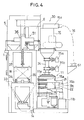
- Figs. 2 to 6 show more details of the abrasive blasting apparatus illustrated in Fig. 1.
- the blasting apparatus is designed as a die finishing apparatus 30 (see Fig. 2).
- the blast nozzle 1 is supported by a triaxial or three-dimensional actuator 31 within the blast chamber 1 which is a box-like structure having a bottom hopper portion according to the illustrated embodiment.
- the controller C (see Fig. 1) for operating the control valves 7a, 7b also controls the triaxial actuator 31 for three-dimensional movement.
- the triaxial actuator 31 includes an X-axis linear guide 31a, a Y-axis linear guide 31b mounted on the X-axis linear guide 31a, and a Z-axis linear guide 31c mounted on the Y-axis linear guide 31b.
- the triaxial actuator 31 itself may be of the known type.
- a feed table 33 On one side of the blast chamber 1 is arranged a feed table 33 which is provided with a pair of guide rails 34 extending into the blast chamber 1. A carriage 35 supporting the workpiece W is supported on the pair of rails 34 for horizontal movement into and out of the blast chamber 1. Obviously, the workpiece W for the die finishing apparatus 30 is a die.
- the blast chamber 1 has an access opening (see Fig. 1) near the feed table 33.
- the access opening is closable by a slide door 37 which is vertically movable by an air cylinder 36.
- the carriage 35 is driven by a drive assembly 38 for horizontal reciprocating movement.
- the drive assembly 38 comprises a first sprocket 39 disposed in the blast chamber 1, a second sprocket 40 arranged on the feed table 33, an endless chain 41 extending between the first and second sprockets 39, 40 in engagement therewith, and a reversible motor 42 connected to the second sprocket 40.
- limit switches (not shown) suitably disposed for generating position signals.
- the motor 42 may be rotated (in the forward or opposite direction) or stopped in response to the signals from the limit switches.
- the first and second abrasive containers 5, 6 (cyclone separators) are disposed obliquely above the blast chamber 1 (upper left in Fig. 2).
- the respective bottom hopper portions of the first and second abrasive containers 5, 6 are connected to the first and second conduit branches 4a, 4b which merge into the abrasive supply conduit 4 connected to the blast nozzle 2, as already described.
- the first and second conduit branches 4a, 4b are provided with the respective control valves 7a, 7b (see Fig. 1).
- the first abrasive container 5 has a top portion provided with an abrasive inlet 43 and a dust outlet 45.
- the abrasive inlet 43 extends horizontally and is connected to the secondary abrasive separating unit 11b through the abrasive feedback conduit 12 (see Fig. 1).
- the dust outlet 45 also extends horizontally and is connected to a dust inlet 50 of the dust collector 10 through the dust conduit 8.
- the second abrasive container 6 has a top portion provided with an abrasive inlet 44 and a dust outlet 46.
- the abrasive inlet 44 extends horizontally and is connected to the secondary abrasive separating unit 11b through the abrasive feedback conduit 13 (Fig. 1).
- the dust outlet 46 also extends horizontally and is connected to another dust inlet 49 of the dust collector 10 through the dust conduit 9.
- the dust collector 10, the abrasive separating system 11 and the abrasive collector 15 are all arranged behind the combined assembly of the blast chamber 1 and the feed table 33.
- the dust collector 10 has a further dust inlet 51
- the abrasive collector 15 has a dust outlet 15a which is connected to the dust inlet 51 of the dust collector 10 through the dust conduit 16.
- the abrasive collector 15 also has an abrasive inlet 15b which is connected to the bottom hopper portion of the blast chamber 1 through the collecting conduit 14 (see Figs. 1, 3 and 4).
- the dust collector 10 may be of the known type which comprises a suction fan 52 for generating a negative pressure, and a plurality of dust collecting elements 53. Dust laden air is sucked into the dust collector 10 under the negative pressure generated by the suction fan 52, and the dust is removed by the dust collecting elements 53.
- the secondary abrasive separating unit 11b comprises a casing 54 in which the screen 26 is arranged in an inclined posture.
- the casing 54 has an abrasive inlet 55 for connection to the conduit 21 to introduce particles of the second abrasive material into the casing 54 above the screen 26.
- the casing 54 also has another abrasive inlet 56 for connection to the conduit 22 to introduce particles of the first abrasive material under the screen 26.
- the casing 54 further has an air inlet 57 for introducing secondary air into the casing above the screen 26. Moreover, the casing 54 has respective abrasive outlets 58, 59 for connection to the respective feedback conduits 12, 13.
- the partition may be made of rubber for example.
- the secondary air introduced through the air inlet 57 keeps a higher pressure above the screen 26 than below it, thereby preventing the smaller particles from passing reversely through the screen. Further, the secondary air also assists the feedback movement of the particles of the second abrasive material through the feedback conduit 12.
- the particles of the first abrasive material introduced into the casing 54 through the other abrasive inlet 56 moves down toward the abrasive outlet 59 while joining with the abrasive particles which has passed downwardly through the screen 26.
- the secondary air also assists the feedback movement of the abrasive particles through the feedback conduit 13.
- a die W to be treated is placed accurately in position on the carriage 35 which is located on the feed table 33.
- the slide door 37 is open because the carriage 35 has been previously retreated out of the blast chamber 1 for taking out a former die (not shown) which has been already treated.
- the carriage 35 together with the supported die W is advanced to a predetermined position within the blast chamber 1, as indicated by phantom lines in Fig. 2.
- the slide door 37 is closed upon entry of the carriage 35 into the blast chamber 1.
- the control valve 7b associated with the second abrasive container 6 is opened.
- the blast nozzle 2 blasts particles (rough finishing coarse particles) of the second abrasive material, entrained in a low-pressure, high-speed air flow, toward the die W.
- the controller C causes the triaxial actuator 31 to move the blast nozzle 2 automatically along a predetermined blasting path for roughly finishing the inner cavity surfaces of the die W in a uniform manner.
- the controller C Upon lapse of a predetermined time or after the triaxial actuator 31 has performed a predetermined movement cycle, the controller C causes the control valve 7b to close while causing the other control valve 7a associated with the first abrasive container to open. As a result, particles (fine finishing particles) of the first abrasive material is blasted through the blast nozzle 2. At this time, again, the controller C causes the triaxial actuator 31 to move the blast nozzle 2 for finely finishing the entire inner cavity surfaces of the die W in a uniform manner.
- the controller C Upon lapse of a predetermined time or after the triaxial actuator 31 has performed a predetermined movement cycle, the controller C causes the control valve 7a to close, and the air source B and the dust collector 10 are stopped. Further, the slide door 37 is opened, and the carriage supporting the treated die W is retreated onto the feed table 33.
- the above steps may be repeated after replacing the treated die W by a new one. In this way, it is possible to perform a surface finishing operation successively with respect to a plurality of dies.
- the die finishing apparatus 30 described above is capable of automatically performing a surface finishing operation of a die cavity which has been conventionally considered to be a troublesome job requiring an intensive work. Further, the triaxial actuator is capable to bringing the blast nozzle 2 accurately at any three-dimensional position as required for suitably treating a die which is worked by electrical discharge machining to have a complicated cavity.
Landscapes
- Engineering & Computer Science (AREA)
- Mechanical Engineering (AREA)
- Cleaning In General (AREA)
- Finish Polishing, Edge Sharpening, And Grinding By Specific Grinding Devices (AREA)
- Nozzles (AREA)
- Moulds For Moulding Plastics Or The Like (AREA)
Applications Claiming Priority (2)
| Application Number | Priority Date | Filing Date | Title |
|---|---|---|---|
| JP5039016A JPH06246636A (ja) | 1993-02-26 | 1993-02-26 | ブラスト装置およびこれを利用した金型仕上げ装置 |
| JP39016/93 | 1993-02-26 |
Publications (2)
| Publication Number | Publication Date |
|---|---|
| EP0612585A1 true EP0612585A1 (de) | 1994-08-31 |
| EP0612585B1 EP0612585B1 (de) | 1998-11-25 |
Family
ID=12541314
Family Applications (1)
| Application Number | Title | Priority Date | Filing Date |
|---|---|---|---|
| EP94301003A Expired - Lifetime EP0612585B1 (de) | 1993-02-26 | 1994-02-11 | Schleuderstrahleinrichtung und Stempel-Endbearbeitungsvorrichtung die diese verwendet |
Country Status (6)
| Country | Link |
|---|---|
| US (1) | US5562531A (de) |
| EP (1) | EP0612585B1 (de) |
| JP (1) | JPH06246636A (de) |
| KR (1) | KR0162508B1 (de) |
| CN (1) | CN1093030A (de) |
| DE (1) | DE69414736T2 (de) |
Cited By (5)
| Publication number | Priority date | Publication date | Assignee | Title |
|---|---|---|---|---|
| FR2804627A1 (fr) * | 2000-02-04 | 2001-08-10 | Gerard Montanier | Installation de sablage |
| GB2383766A (en) * | 2002-01-04 | 2003-07-09 | Workinter Ltd | Method and apparatus for selective removal of materials present in one or more layers on an object |
| WO2004080656A1 (en) * | 2003-03-14 | 2004-09-23 | Workinter Limited | Method for selective removal of materials present in one or more layers on an object, and apparatus for implementation of this method |
| EP2377649A1 (de) * | 2010-04-15 | 2011-10-19 | KOMPOFERM GmbH | Strahlmittel und Strahlverfahren |
| US9962809B2 (en) | 2012-10-12 | 2018-05-08 | Kompoferm Gmbh | Blasting agent and blasting method |
Families Citing this family (35)
| Publication number | Priority date | Publication date | Assignee | Title |
|---|---|---|---|---|
| TW277020B (en) * | 1994-04-22 | 1996-06-01 | Richihil Kk | Separating device of blasting particle |
| JP3783876B2 (ja) * | 1995-01-12 | 2006-06-07 | 株式会社シー・エス・シー | 負圧吸引ブラスト装置並びにその方法 |
| JPH10329890A (ja) * | 1997-05-30 | 1998-12-15 | Koei:Kk | 粉粒体供給装置 |
| EP1075353B1 (de) * | 1998-05-07 | 2002-12-04 | Pittman Vacuum Blasting Systems Inc. | System zur trennung von verunreinigungen von strahlmitteln |
| US6202657B1 (en) | 1998-07-16 | 2001-03-20 | Car-Tec Company | Safety and environmental workbench |
| JP4063498B2 (ja) * | 2000-03-02 | 2008-03-19 | 株式会社リコー | 画像形成装置 |
| AUPQ930800A0 (en) * | 2000-08-10 | 2000-08-31 | Megara (Australia) Pty Ltd | Finishing of metal surfaces and related applications |
| AU7742001A (en) * | 2000-08-10 | 2002-02-25 | Megara Australia Pty Ltd | Finishing of metal surfaces and related applications |
| US6977096B2 (en) * | 2002-10-03 | 2005-12-20 | Material Technologies, Inc. | Method of coating surface with tungsten disulfide |
| US20040187979A1 (en) * | 2003-03-31 | 2004-09-30 | Material Technologies, Inc. | Cutting tool body having tungsten disulfide coating and method for accomplishing same |
| US7052362B2 (en) * | 2003-10-29 | 2006-05-30 | Lynn William R | Blendable blasting media and method of reusing and discharging same |
| KR100572994B1 (ko) * | 2005-01-26 | 2006-04-24 | (주)유창금속 | 금형 자동 다듬질 장치 |
| GB0514888D0 (en) * | 2005-07-20 | 2005-08-24 | Haslett Basil | Glass etching |
| JP4849322B2 (ja) * | 2006-07-11 | 2012-01-11 | 新東工業株式会社 | ショット処理装置 |
| EP2076338B2 (de) * | 2006-09-25 | 2022-01-26 | Basf Se | Verfahren zum klassieren wasserabsorbierender polymerpartikel |
| US20080176487A1 (en) * | 2007-01-19 | 2008-07-24 | Armstrong Jay T | Portable cleaning and blasting system for multiple media types, including dry ice and grit |
| WO2012014542A1 (ja) * | 2010-07-27 | 2012-02-02 | 新東工業株式会社 | ショットピーニング方法及びショットピーニング装置 |
| JP2014039961A (ja) * | 2010-12-24 | 2014-03-06 | Sintokogio Ltd | ショット処理装置 |
| CN103213279B (zh) * | 2012-01-19 | 2015-11-18 | 研能科技股份有限公司 | 自动粉末回收再利用系统 |
| CN103286073A (zh) * | 2012-02-29 | 2013-09-11 | 宝山钢铁股份有限公司 | 一种混合射流清洗的介质回收供应方法 |
| JP2013242154A (ja) * | 2012-05-17 | 2013-12-05 | Toyo Union:Kk | 除染方法及び除染装置 |
| JP5702331B2 (ja) * | 2012-05-17 | 2015-04-15 | 株式会社東洋ユニオン | 汚染物質除去装置 |
| JP2013242153A (ja) * | 2012-05-17 | 2013-12-05 | Toyo Union:Kk | 除染方法及び除染装置 |
| EP3145674A4 (de) * | 2014-05-22 | 2018-07-18 | Dardi International Corporation | Granatextraktionssystem und verfahren zur verwendung davon |
| JP6603482B2 (ja) * | 2015-05-27 | 2019-11-06 | 株式会社アルプスエンジニアリング | 研磨材分級装置 |
| CN107159562A (zh) * | 2017-07-17 | 2017-09-15 | 苏州三峰激光科技有限公司 | 筛分装置以及钛合金粉末筛分系统 |
| CN107695898B (zh) * | 2017-11-22 | 2023-10-17 | 河南理工大学 | 一种磨料气体射流磨料回收装置及方法 |
| DE102020118828A1 (de) * | 2020-07-16 | 2022-01-20 | Dyemansion Gmbh | Betreiben einer Strahlanlage mit Steuerdaten |
| CN112658997B (zh) * | 2020-12-17 | 2023-02-28 | 陕西法士特齿轮有限责任公司 | 一种组合强化喷丸装置及方法 |
| CN113146482A (zh) * | 2021-05-17 | 2021-07-23 | 山东绿钢环保科技股份有限公司 | 一种磨料射流除鳞系统 |
| US20230060735A1 (en) * | 2021-09-01 | 2023-03-02 | Engineered Abrasives, Inc. | Media processing apparatus and method of same |
| WO2023081606A1 (en) * | 2021-11-02 | 2023-05-11 | Flow International Corporation | Abrasive fluid jet with recycling system for abrasives and methods of use of same |
| TWI841000B (zh) * | 2022-10-14 | 2024-05-01 | 財團法人工業技術研究院 | 懸浮磨料噴射流的加工方法及加工系統 |
| US12466031B2 (en) | 2022-10-27 | 2025-11-11 | Flow International Corporation | Systems and apparatus for use of wet recycled abrasive and methods of operation of said systems and apparatus |
| CN115847298A (zh) * | 2022-12-26 | 2023-03-28 | 上海天阳钢管有限公司 | 一种新型喷砂机 |
Citations (13)
| Publication number | Priority date | Publication date | Assignee | Title |
|---|---|---|---|---|
| US3386573A (en) * | 1967-02-21 | 1968-06-04 | Agrostroj Prostejov Np | Apparatus for continuous recovery and separation and cleaning of grit |
| US3392491A (en) * | 1965-08-03 | 1968-07-16 | Textron Inc | Particle segregating system |
| US3631631A (en) * | 1970-01-21 | 1972-01-04 | Dental Gold Co | Pneumatic abrasive cutting apparatus |
| DE3131002A1 (de) * | 1981-08-05 | 1983-03-24 | Sergiu Dipl.-Ing. 8000 München Caftanat | Automatische druckstrahlanlage mit genauer und reproduzierbarer dosierung des strahlmittels und kontinuierlichem betrieb |
| EP0150338A2 (de) * | 1983-12-08 | 1985-08-07 | Olavi Fagerroos Mauno | Trockenputzkabine |
| US4581913A (en) * | 1983-07-27 | 1986-04-15 | Luster Finish, Inc. | Method for improving the release and finish characteristics of metal stamping dies |
| US4773189A (en) * | 1985-11-01 | 1988-09-27 | Macmillan Gregory D | Separation system for polymeric blast media |
| US4882881A (en) * | 1987-02-24 | 1989-11-28 | Progressive Blasting Systems, Inc. | Robot positioner and seal arrangement for a closed chamber |
| US4928440A (en) * | 1987-03-30 | 1990-05-29 | Container Products Corp. | Decontamination booth |
| DE9016425U1 (de) * | 1989-12-05 | 1991-03-14 | Kiener, Heinz, Heimenhausen, Bern | Schalteinrichtung für ein Sandstrahlgerät |
| US5049260A (en) * | 1990-08-29 | 1991-09-17 | Spears Richard L | Blast cleaning wet media feed and separation system |
| WO1991018712A2 (de) * | 1990-06-05 | 1991-12-12 | Siemens Aktiengesellschaft | Verfahren und vorrichtung zur dekontamination radioaktiv kontaminierter oberflächen |
| EP0522485A1 (de) * | 1991-07-11 | 1993-01-13 | Kaltenbach & Voigt Gmbh & Co. | Bearbeitungsgerät zum Bearbeiten von feinwerktechnischen, insbesondere dentaltechnischen Werkstücken in einem von einem Gehäuse umgebenen Bearbeitungsraum |
Family Cites Families (10)
| Publication number | Priority date | Publication date | Assignee | Title |
|---|---|---|---|---|
| US3662886A (en) * | 1970-02-05 | 1972-05-16 | Catalyst Services Inc | Handling apparatus for particulate dry product |
| US3984943A (en) * | 1974-10-17 | 1976-10-12 | Ishikawajima-Harima Jukogyo Kabushiki Kaisha | Apparatus for treating surfaces of sheet steel or the like |
| US4505077A (en) * | 1983-03-16 | 1985-03-19 | Empire Abrasive Equipment Corporation | Cabinet door interlock |
| US4993200A (en) * | 1986-03-11 | 1991-02-19 | Kawasaki Steel Techno-Research Corp | Pollution free blaster system and blaster head therefor |
| US4793103A (en) * | 1986-08-19 | 1988-12-27 | Acd, Inc. | Continuous deflashing apparatus for molded articles |
| DE3844649C2 (de) * | 1987-06-23 | 1992-04-23 | Taiyo Sanso Co. Ltd., Osaka, Jp | |
| US4769956A (en) * | 1987-09-02 | 1988-09-13 | Engineered Abrasives, Inc. | Abrasive cleaning and treating device |
| US5035089A (en) * | 1990-01-29 | 1991-07-30 | Pauli & Griffin | Blast media recovery and cleaning system |
| US5269424A (en) * | 1991-06-26 | 1993-12-14 | Corcon | Mobile separation method system for abrasive blasting material |
| US5334019A (en) * | 1991-12-06 | 1994-08-02 | American Dental Technologies, Inc. | Dental air abrasive system |
-
1993
- 1993-02-26 JP JP5039016A patent/JPH06246636A/ja active Pending
-
1994
- 1994-02-04 US US08/191,598 patent/US5562531A/en not_active Expired - Fee Related
- 1994-02-11 EP EP94301003A patent/EP0612585B1/de not_active Expired - Lifetime
- 1994-02-11 DE DE69414736T patent/DE69414736T2/de not_active Expired - Fee Related
- 1994-02-26 CN CN94102300A patent/CN1093030A/zh active Pending
- 1994-02-26 KR KR1019940003700A patent/KR0162508B1/ko not_active Expired - Fee Related
Patent Citations (13)
| Publication number | Priority date | Publication date | Assignee | Title |
|---|---|---|---|---|
| US3392491A (en) * | 1965-08-03 | 1968-07-16 | Textron Inc | Particle segregating system |
| US3386573A (en) * | 1967-02-21 | 1968-06-04 | Agrostroj Prostejov Np | Apparatus for continuous recovery and separation and cleaning of grit |
| US3631631A (en) * | 1970-01-21 | 1972-01-04 | Dental Gold Co | Pneumatic abrasive cutting apparatus |
| DE3131002A1 (de) * | 1981-08-05 | 1983-03-24 | Sergiu Dipl.-Ing. 8000 München Caftanat | Automatische druckstrahlanlage mit genauer und reproduzierbarer dosierung des strahlmittels und kontinuierlichem betrieb |
| US4581913A (en) * | 1983-07-27 | 1986-04-15 | Luster Finish, Inc. | Method for improving the release and finish characteristics of metal stamping dies |
| EP0150338A2 (de) * | 1983-12-08 | 1985-08-07 | Olavi Fagerroos Mauno | Trockenputzkabine |
| US4773189A (en) * | 1985-11-01 | 1988-09-27 | Macmillan Gregory D | Separation system for polymeric blast media |
| US4882881A (en) * | 1987-02-24 | 1989-11-28 | Progressive Blasting Systems, Inc. | Robot positioner and seal arrangement for a closed chamber |
| US4928440A (en) * | 1987-03-30 | 1990-05-29 | Container Products Corp. | Decontamination booth |
| DE9016425U1 (de) * | 1989-12-05 | 1991-03-14 | Kiener, Heinz, Heimenhausen, Bern | Schalteinrichtung für ein Sandstrahlgerät |
| WO1991018712A2 (de) * | 1990-06-05 | 1991-12-12 | Siemens Aktiengesellschaft | Verfahren und vorrichtung zur dekontamination radioaktiv kontaminierter oberflächen |
| US5049260A (en) * | 1990-08-29 | 1991-09-17 | Spears Richard L | Blast cleaning wet media feed and separation system |
| EP0522485A1 (de) * | 1991-07-11 | 1993-01-13 | Kaltenbach & Voigt Gmbh & Co. | Bearbeitungsgerät zum Bearbeiten von feinwerktechnischen, insbesondere dentaltechnischen Werkstücken in einem von einem Gehäuse umgebenen Bearbeitungsraum |
Cited By (12)
| Publication number | Priority date | Publication date | Assignee | Title |
|---|---|---|---|---|
| FR2804627A1 (fr) * | 2000-02-04 | 2001-08-10 | Gerard Montanier | Installation de sablage |
| GB2383766A (en) * | 2002-01-04 | 2003-07-09 | Workinter Ltd | Method and apparatus for selective removal of materials present in one or more layers on an object |
| GB2383766B (en) * | 2002-01-04 | 2005-07-27 | Workinter Ltd | Method for selective removal of materials present in one or more layers on an object and apparatus for implementation of this method |
| WO2004080656A1 (en) * | 2003-03-14 | 2004-09-23 | Workinter Limited | Method for selective removal of materials present in one or more layers on an object, and apparatus for implementation of this method |
| US7344651B2 (en) | 2003-03-14 | 2008-03-18 | Workinter Limited | Method for selective removal of materials present in one or more layers on an object, and apparatus for implementation of this method |
| EP2377649A1 (de) * | 2010-04-15 | 2011-10-19 | KOMPOFERM GmbH | Strahlmittel und Strahlverfahren |
| WO2011127952A1 (de) * | 2010-04-15 | 2011-10-20 | Kompoferm Gmbh | Strahlmittel und strahlverfahren |
| US20130029563A1 (en) * | 2010-04-15 | 2013-01-31 | Kompoferm Gmbh | Blasting agent and blasting method |
| KR101395373B1 (ko) * | 2010-04-15 | 2014-05-14 | 콤포펌 게엠베하 | 블라스팅 매체 및 블라스팅 방법 |
| EP2913149A1 (de) * | 2010-04-15 | 2015-09-02 | Kompoferm GmbH | Strahlverfahren und -vorrichtung |
| US9314902B2 (en) | 2010-04-15 | 2016-04-19 | Kompoferm Gmbh | Blasting agent and blasting method |
| US9962809B2 (en) | 2012-10-12 | 2018-05-08 | Kompoferm Gmbh | Blasting agent and blasting method |
Also Published As
| Publication number | Publication date |
|---|---|
| US5562531A (en) | 1996-10-08 |
| DE69414736T2 (de) | 1999-07-22 |
| CN1093030A (zh) | 1994-10-05 |
| KR940019409A (ko) | 1994-09-14 |
| EP0612585B1 (de) | 1998-11-25 |
| KR0162508B1 (ko) | 1999-10-01 |
| JPH06246636A (ja) | 1994-09-06 |
| DE69414736D1 (de) | 1999-01-07 |
Similar Documents
| Publication | Publication Date | Title |
|---|---|---|
| EP0612585B1 (de) | Schleuderstrahleinrichtung und Stempel-Endbearbeitungsvorrichtung die diese verwendet | |
| US7421872B2 (en) | Shot-blasting installation for blasting work pieces made from light metal alloys | |
| WO2007049393A1 (ja) | ヒューム処理方法および処理装置 | |
| KR101928748B1 (ko) | 쇼트볼 분리 및 세정장치를 구비한 연속 벨트 컨베이어 방식의 쇼트 블라스트 시스템 | |
| JP5742851B2 (ja) | ショット処理装置 | |
| EP1757407B1 (de) | Ausstossbearbeitungsvorrichtung | |
| KR101928700B1 (ko) | 연속 벨트 컨베이어 방식의 쇼트 블라스트 시스템 | |
| CN1980772B (zh) | 喷射处理装置 | |
| KR101196526B1 (ko) | 블라스트 가공 장치 | |
| WO2016136443A1 (ja) | ノズル組立体及びこのノズル組立体を用いた表面処理方法 | |
| JPS637501Y2 (de) | ||
| US5443412A (en) | Blasting machining apparatus using abrasive particles like powder | |
| CA2241822A1 (en) | Method for purging and cleaning of recesses of at least one workpiece | |
| CN2202012Y (zh) | 直压式内循环喷砂机 | |
| WO2023081606A9 (en) | Abrasive fluid jet with recycling system for abrasives and methods of use of same | |
| KR200451727Y1 (ko) | 복합식 블라스트 기계 | |
| CN110052970B (zh) | 分级机构 | |
| KR20220155433A (ko) | 분말 베드에서 인쇄되는 접착성 분말 입자들로 제작된 3차원 컴포넌트를 세척하기 위한 장치 | |
| KR20210058813A (ko) | 블라스트 가공 장치 및 블라스트 가공 방법 | |
| CN218965126U (zh) | 喷砂机砂料回收装置 | |
| US20210268515A1 (en) | Magnetic separating apparatus and magnetic sorting method | |
| JP2931263B2 (ja) | ブラスト加工装置 | |
| JP2598234B2 (ja) | 浮遊ショットブラスト加工方法及び装置 | |
| RU2828057C2 (ru) | Машина для абразивной струйной обработки поверхностей крупноразмерных обрабатываемых деталей | |
| KR100582450B1 (ko) | 보철물 후가공용 팬 블라스터 |
Legal Events
| Date | Code | Title | Description |
|---|---|---|---|
| PUAI | Public reference made under article 153(3) epc to a published international application that has entered the european phase |
Free format text: ORIGINAL CODE: 0009012 |
|
| AK | Designated contracting states |
Kind code of ref document: A1 Designated state(s): DE FR GB IT |
|
| 17P | Request for examination filed |
Effective date: 19950117 |
|
| 17Q | First examination report despatched |
Effective date: 19961227 |
|
| GRAG | Despatch of communication of intention to grant |
Free format text: ORIGINAL CODE: EPIDOS AGRA |
|
| GRAG | Despatch of communication of intention to grant |
Free format text: ORIGINAL CODE: EPIDOS AGRA |
|
| GRAG | Despatch of communication of intention to grant |
Free format text: ORIGINAL CODE: EPIDOS AGRA |
|
| GRAH | Despatch of communication of intention to grant a patent |
Free format text: ORIGINAL CODE: EPIDOS IGRA |
|
| GRAH | Despatch of communication of intention to grant a patent |
Free format text: ORIGINAL CODE: EPIDOS IGRA |
|
| GRAA | (expected) grant |
Free format text: ORIGINAL CODE: 0009210 |
|
| AK | Designated contracting states |
Kind code of ref document: B1 Designated state(s): DE FR GB IT |
|
| PG25 | Lapsed in a contracting state [announced via postgrant information from national office to epo] |
Ref country code: IT Free format text: LAPSE BECAUSE OF FAILURE TO SUBMIT A TRANSLATION OF THE DESCRIPTION OR TO PAY THE FEE WITHIN THE PRESCRIBED TIME-LIMIT;WARNING: LAPSES OF ITALIAN PATENTS WITH EFFECTIVE DATE BEFORE 2007 MAY HAVE OCCURRED AT ANY TIME BEFORE 2007. THE CORRECT EFFECTIVE DATE MAY BE DIFFERENT FROM THE ONE RECORDED. Effective date: 19981125 |
|
| REF | Corresponds to: |
Ref document number: 69414736 Country of ref document: DE Date of ref document: 19990107 |
|
| PGFP | Annual fee paid to national office [announced via postgrant information from national office to epo] |
Ref country code: FR Payment date: 19990120 Year of fee payment: 6 |
|
| PGFP | Annual fee paid to national office [announced via postgrant information from national office to epo] |
Ref country code: DE Payment date: 19990206 Year of fee payment: 6 |
|
| ET | Fr: translation filed | ||
| PGFP | Annual fee paid to national office [announced via postgrant information from national office to epo] |
Ref country code: GB Payment date: 19990212 Year of fee payment: 6 |
|
| REG | Reference to a national code |
Ref country code: FR Ref legal event code: TP |
|
| REG | Reference to a national code |
Ref country code: GB Ref legal event code: 732E |
|
| PLBE | No opposition filed within time limit |
Free format text: ORIGINAL CODE: 0009261 |
|
| STAA | Information on the status of an ep patent application or granted ep patent |
Free format text: STATUS: NO OPPOSITION FILED WITHIN TIME LIMIT |
|
| 26N | No opposition filed | ||
| PG25 | Lapsed in a contracting state [announced via postgrant information from national office to epo] |
Ref country code: GB Free format text: LAPSE BECAUSE OF NON-PAYMENT OF DUE FEES Effective date: 20000211 |
|
| GBPC | Gb: european patent ceased through non-payment of renewal fee |
Effective date: 20000211 |
|
| PG25 | Lapsed in a contracting state [announced via postgrant information from national office to epo] |
Ref country code: FR Free format text: LAPSE BECAUSE OF NON-PAYMENT OF DUE FEES Effective date: 20001031 |
|
| PG25 | Lapsed in a contracting state [announced via postgrant information from national office to epo] |
Ref country code: DE Free format text: LAPSE BECAUSE OF NON-PAYMENT OF DUE FEES Effective date: 20001201 |
|
| REG | Reference to a national code |
Ref country code: FR Ref legal event code: ST |