EP0612601A1 - Kniegelenk-Verschluss für Pressen, insbesondere für Kunststoff-Spritzgiessmaschinen - Google Patents
Kniegelenk-Verschluss für Pressen, insbesondere für Kunststoff-Spritzgiessmaschinen Download PDFInfo
- Publication number
- EP0612601A1 EP0612601A1 EP93830067A EP93830067A EP0612601A1 EP 0612601 A1 EP0612601 A1 EP 0612601A1 EP 93830067 A EP93830067 A EP 93830067A EP 93830067 A EP93830067 A EP 93830067A EP 0612601 A1 EP0612601 A1 EP 0612601A1
- Authority
- EP
- European Patent Office
- Prior art keywords
- heel
- toggle
- pressure
- stop
- moving plate
- Prior art date
- Legal status (The legal status is an assumption and is not a legal conclusion. Google has not performed a legal analysis and makes no representation as to the accuracy of the status listed.)
- Ceased
Links
- 238000001746 injection moulding Methods 0.000 title claims description 14
- 229920003023 plastic Polymers 0.000 title claims description 14
- 239000004033 plastic Substances 0.000 title claims description 14
- 239000000463 material Substances 0.000 title claims description 12
- 125000006850 spacer group Chemical group 0.000 claims description 24
- 230000006835 compression Effects 0.000 claims description 5
- 238000007906 compression Methods 0.000 claims description 5
- 238000002347 injection Methods 0.000 claims description 5
- 239000007924 injection Substances 0.000 claims description 5
- 238000000034 method Methods 0.000 claims description 3
- 238000010276 construction Methods 0.000 description 3
- 238000000465 moulding Methods 0.000 description 3
- 238000007599 discharging Methods 0.000 description 1
- 230000036316 preload Effects 0.000 description 1
Images

Classifications
-
- B—PERFORMING OPERATIONS; TRANSPORTING
- B29—WORKING OF PLASTICS; WORKING OF SUBSTANCES IN A PLASTIC STATE IN GENERAL
- B29C—SHAPING OR JOINING OF PLASTICS; SHAPING OF MATERIAL IN A PLASTIC STATE, NOT OTHERWISE PROVIDED FOR; AFTER-TREATMENT OF THE SHAPED PRODUCTS, e.g. REPAIRING
- B29C45/00—Injection moulding, i.e. forcing the required volume of moulding material through a nozzle into a closed mould; Apparatus therefor
- B29C45/17—Component parts, details or accessories; Auxiliary operations
- B29C45/64—Mould opening, closing or clamping devices
- B29C45/68—Mould opening, closing or clamping devices hydro-mechanical
- B29C45/681—Mould opening, closing or clamping devices hydro-mechanical using a toggle mechanism as mould clamping device
Definitions
- This invention relates to a toggle-action clamp for presses of the kind used for injection molding plastics materials, comprising: at least a pair of pillars having parallel axes and a stationary plate mounted on axial ends thereof; a moving plate guided along said pillars for sliding movement toward and away from the stationary plate to clamp a mold between said plates; a pressure heel associated with said pillars on the opposite side from the stationary plate with respect to the moving plate; and a toggle-action mechanism arranged to act between the pressure heel and the moving plate and cause the latter to perform predetermined mold clamping and releasing strokes, respectively, and apply a predetermined closing load to the mold.
- the invention also concerns a press for injection molding plastics materials which incorporates a toggle-action clamp according to the invention.
- toggle-action clamps have been known in a range of different designs. Some prior constructions are illustrated in Perucca, “Dizionario di Ingegneria”, UTET Publishers, at the entry “Stampaggio”.
- a first example of a clamp is the so-called direct toggle-action clamp.
- the toggle-action mechanism is arranged to drive the moving plate toward and away from the stationary plate, as well as to clamp the mold by application of a predetermined mold closing load.
- the toggle-action mechanism has a number of well-recognized advantages. Some of these relate to that, for a given rate of advance or the plunger to which the moving plate is connected via a crosshead device, a fast advance rate during the initial portion of the stroke and slow advance rate during the final portion can be obtained for the moving plate.
- the clamping phase being a slow one, takes place under a condition of high mold preloading.
- the release phase likewise takes place at a slow rate, because the mechanism operation is reversed. Accordingly, the moving plate can be applied a large force through the toggle-action mechanism for opening the mould.
- a second example of a related clamp is represented by the so-called plunger and toggle-action clamp.
- the forward stroke of the moving plate is entirely produced through the use of oil-operated jacks intervening between the pressure heel and the moving plate.
- the toggle-action mechanism is supported on the moving plate and is only operated to apply a predetermined closing load to the mold by performing a compression member function between the pressure heel and the moving plate.
- the forward stroke of the moving plate can be made significantly longer than that of the first example, so that pieces of considerable length can be molded thereby.
- the second-mentioned prior approach has some disadvantages of its own, among which is the fact that the forward movement of the moving plate occurs at a slow rate compared to that to be obtained with direct toggle-action clamps.
- a large die-opening force cannot be exerted on the moving plate because this function is served solely by the oil-operated jacks provided for driving the moving plate.
- a further example of a clamp for plastics injection molding presses is known in the industry by the name of "Hydroblock" clamp.
- the pressure heel is slidable along the pillars and locates somewhere between the moving plate and a stop heel.
- Oil-operated jacks are provided between the stop and the pressure heels for shifting the pressure heel toward and away from the stationary plate.
- Arranged between the pressure heel and the moving plate are additional oil-operated actuators for clamping the moving plate against the stationary plate and applying the closing load to the mold.
- the underlying problem of this invention is to provide a toggle-action clamp for presses, particularly presses used for injection molding plastics materials, which is designed and constructed to enable pieces of considerable length to be molded, and concurrently the moving plate to be driven forward at a fast rate.
- this clamp shall enable application of a high closing load to the mold, as well as application of a large force to the moving plate for opening the mold.
- the actuator means only are to drive the pressure heel back and forth, which makes the molding of markedly elongate pieces feasible.
- the toggle-action mechanism enables a high closing load to be applied to the mold and a large force to the moving plate for opening the mold. Further, that mechanism adds, to the overall stroke length of the moving plate, a limited but fast segment of movement of the moving plate toward and away from the stationary plate. Also, the moving plate can be driven toward and away the stationary plate by the combined actions of the actuator means and the toggle-action mechanism to provide a longer and faster overall stroke against a limited delivery of pressurized oil to the respective jacks.
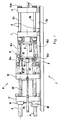
- a press for injection molding plastics materials of which a machine bed 2 and a clamp, generally indicated at 8, are depicted.
- the press 1 includes straight horizontal guiding means 3 which comprise a guide 3a formed on the bed 2 and two pillar pairs 3b extending parallel to one another and to the guide 3a.
- the axially opposed end regions of the pillars 3b are designated 4 and 5, respectively.
- end retainers 6a Mounted on the end 5 by means of end retainers 6a is a stationary plate 6 which is through-penetrated by an injection conduit 6b.
- a moving plate 7 which can slide along the guide means 3.
- the stationary plate 6 and moving plate 7 carry respective mold parts (die and punch) not shown in the drawings.
- a stripper device 9 Conventionally associated with the moving plate 7 is a stripper device 9 for shaking the molding out of the mold and discharging it.
- a pressure heel 10 is mounted slidably on the guiding means 3, on the opposite side of the moving plate 7 relatively to the stationary plate 6, so that the moving plate 7 is intermediate to the stationary plate and the pressure heel.
- a toggle-action mechanism Located between the pressure heel 10 and the moving plate 7 is a toggle-action mechanism, generally shown at 11, which is operative to drive the moving plate 7 through a predetermined stroke toward and away from the stationary plate 6.
- the toggle-action mechanism comprises a hydraulic jack having a cylinder 12 attached to the pressure heel 10 and a piston rod 13 fitted with a crosshead 14 at its free end.
- This crosshead 14 is connected, in turn, as by connecting rods 15, to respective connecting rod pairs 16a,b pivoted to one another as well as to the pressure heel and the moving plate, respectively.
- the specific design of such connecting rods, and their connection to the crosshead, is well-known in the technical field of presses for injection molding plastics materials equipped with a toggle-action clamp.
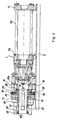
- a stop heel 17 which can be adjusted in position and locked along the end sections 4 of the aforesaid pillars by means of sliding movement adjusters 18 of the kind normally used in conventional clamps to lock the pressure heel adjustably to the pillars.
- actuator means which consist of a pair of hydraulic jacks 19 arranged to shift the pressure heel 10 toward and away from the stationary plate 6.
- a tubular spacer 20 which extends parallel to the guiding means 3 at the location of an opening 21 formed axially through the stop heel 17.
- the opposite ends of the spacer 20 are denoted by 20a and 20b, respectively.
- the end 20b is attached to the pressure heel 10 by a flange connection 28 whereby the spacer can be locked to the surface of the pressure heel 10 facing the stop heel.
- the end 20a of the spacer is adapted to be releasably locked to the stop heel 17 in both axial directions.
- Axial locking means are provided for the purpose which include, for the constraint intended to limit the axial movement of the pressure heel 10 away from the stop heel 17, a ring 22 having a shoulder 23 adapted to abut against a corresponding shoulder 24 on the stop heel.
- a hitching device which comprises two half-jaws 25 being guided along a radial direction on the pressure heel 10 but fast for travelling therewith, which are adapted to be clamped tightly around the spacer 20 by the action of respective hydraulic jacks 26, at a location where a radial shoulder surface 27 of the spacer abuts axially against the jaws 25.
- the jacks 19 are actuated to drive the pressure heel 10 along the guiding means 3 toward the stationary plate 6.
- oil is delivered under a pressure to the hydraulic jack 12 of the toggle-action mechanism 11 such that the stroke from it can be initiated which tends to bring the moving plate 7 toward the stationary plate 6.
- the forward movement should be completed of the pressure heel toward the working condition in which the shoulder 23 on the ring 22 abuts against the corresponding shoulder 24 on the stop heel 17.
- the two half-jaws 25 of the hitching device can be tightened around the spacer 20 in a position where the radial shoulder surface 27 of the spacer abuts axially against the jaws 25.
- the jacks 26 are operated to lock the spacer 20 axially with respect to the stop heel 17 through said jaws.
- the stroke movement of the jack 12 for the toggle-action mechanism 11 can be brought to an end, by clamping the mold between the moving 7 and stationary 6 plates under a selected preload.
- the spacer 20 will be acting as a compression member between the pressure heel 10 and the stop heel 17 to transfer, over to the stop heel, the thrust from the toggle-action mechanism 11 to the pressure heel.
- the injection of plastics material into the mold can be performed conventionally.
- the jack 12 of the toggle-action mechanism is first operated in reverse to initially remove the mold closing load and then open the mold by driving the moving plate 7 away from the stationary plate 6 through the toggle-action mechanism 11.
- the spacer 20 is used as a tension member to transfer, over to the stop heel, the pull -- which may occasionally attain high values -- exerted by the toggle-action mechanism 11 on the pressure heel 10 to open the mold.
- the hitching device is operated to disengage the two half-jaws 25 from the spacer 20 to again allow it to slide freely through the opening 21 in the stop heel 17. Accordingly, by operating the jacks 19 in reverse, the pressure heel can be returned to the stop heel and the molding removed from the mold.
- the invention achieves its objects and affords a number of advantages over the prior art.
- a large bias force can be exerted during the mold opening through the toggle-action mechanism provided. This feature is useful to counteract the proneness of the two mold parts to stick together, as is specially manifest on injection molding elongate pieces in the direction of the pillar axes.
- This construction also allow a clamping mechanism to be provided using the same parts as are normally employed in the construction of conventional toggle-action clamps, by suitably lengthening the pillars and adding the stop heel, jack actuators, spacer, and locking means associated therewith.
Landscapes
- Engineering & Computer Science (AREA)
- Manufacturing & Machinery (AREA)
- Mechanical Engineering (AREA)
- Moulds For Moulding Plastics Or The Like (AREA)
Priority Applications (1)
| Application Number | Priority Date | Filing Date | Title |
|---|---|---|---|
| EP93830067A EP0612601A1 (de) | 1993-02-24 | 1993-02-24 | Kniegelenk-Verschluss für Pressen, insbesondere für Kunststoff-Spritzgiessmaschinen |
Applications Claiming Priority (1)
| Application Number | Priority Date | Filing Date | Title |
|---|---|---|---|
| EP93830067A EP0612601A1 (de) | 1993-02-24 | 1993-02-24 | Kniegelenk-Verschluss für Pressen, insbesondere für Kunststoff-Spritzgiessmaschinen |
Publications (1)
| Publication Number | Publication Date |
|---|---|
| EP0612601A1 true EP0612601A1 (de) | 1994-08-31 |
Family
ID=8215123
Family Applications (1)
| Application Number | Title | Priority Date | Filing Date |
|---|---|---|---|
| EP93830067A Ceased EP0612601A1 (de) | 1993-02-24 | 1993-02-24 | Kniegelenk-Verschluss für Pressen, insbesondere für Kunststoff-Spritzgiessmaschinen |
Country Status (1)
| Country | Link |
|---|---|
| EP (1) | EP0612601A1 (de) |
Cited By (1)
| Publication number | Priority date | Publication date | Assignee | Title |
|---|---|---|---|---|
| US7134863B2 (en) * | 2004-04-05 | 2006-11-14 | Fanuc Ltd | Mold clamping mechanism for injection molding machine |
Citations (6)
| Publication number | Priority date | Publication date | Assignee | Title |
|---|---|---|---|---|
| FR1084197A (fr) * | 1953-04-25 | 1955-01-17 | Viennoise De Const Mecaniques | Dispositif de fermeture pour moule d'injection et analogues |
| GB771846A (en) * | 1955-05-02 | 1957-04-03 | Nat Lead Co | Improvements in or relating to tandem toggle presses |
| US3262158A (en) * | 1962-07-16 | 1966-07-26 | Reimer Vinzenz Von | Injection or pressure fusion machine |
| FR1516120A (fr) * | 1967-01-24 | 1968-03-08 | Dispositif de fermeture de moule pour machine à couler sous pression | |
| FR2345277A1 (fr) * | 1976-03-26 | 1977-10-21 | Plastic Metal Spa | Appareillage pour la fermeture des moules de formage |
| EP0027212A1 (de) * | 1979-10-10 | 1981-04-22 | Pont-A-Mousson S.A. | Automatische Regelvorrichtung einer Verstell- und Verschlussvorrichtung einer Giessform |
-
1993
- 1993-02-24 EP EP93830067A patent/EP0612601A1/de not_active Ceased
Patent Citations (6)
| Publication number | Priority date | Publication date | Assignee | Title |
|---|---|---|---|---|
| FR1084197A (fr) * | 1953-04-25 | 1955-01-17 | Viennoise De Const Mecaniques | Dispositif de fermeture pour moule d'injection et analogues |
| GB771846A (en) * | 1955-05-02 | 1957-04-03 | Nat Lead Co | Improvements in or relating to tandem toggle presses |
| US3262158A (en) * | 1962-07-16 | 1966-07-26 | Reimer Vinzenz Von | Injection or pressure fusion machine |
| FR1516120A (fr) * | 1967-01-24 | 1968-03-08 | Dispositif de fermeture de moule pour machine à couler sous pression | |
| FR2345277A1 (fr) * | 1976-03-26 | 1977-10-21 | Plastic Metal Spa | Appareillage pour la fermeture des moules de formage |
| EP0027212A1 (de) * | 1979-10-10 | 1981-04-22 | Pont-A-Mousson S.A. | Automatische Regelvorrichtung einer Verstell- und Verschlussvorrichtung einer Giessform |
Cited By (1)
| Publication number | Priority date | Publication date | Assignee | Title |
|---|---|---|---|---|
| US7134863B2 (en) * | 2004-04-05 | 2006-11-14 | Fanuc Ltd | Mold clamping mechanism for injection molding machine |
Similar Documents
| Publication | Publication Date | Title |
|---|---|---|
| EP0596271B1 (de) | Spritzgiessmachine vom örtlichen Druckbeaufschlagungstyp | |
| CA2673694C (en) | Molding-system clamp | |
| US3093863A (en) | Die-casting or injection-moulding machines | |
| US3327353A (en) | Mold closure apparatus | |
| EP1366839A2 (de) | Spannvorrichtung für eine Druckgiessmaschine | |
| US3346924A (en) | Injection mold locking device | |
| US4106885A (en) | Hydraulic moulding presses | |
| TWI356763B (en) | Molding-system lock | |
| DE2319181A1 (de) | Spritzmaschine, z.b. fuer kunststoff | |
| DE2117104C3 (de) | Hydraulische Streckrichtmaschine für Profile und Bleche | |
| DE2111830B2 (de) | Zweistufige Klemm oder Schließ vorrichtung, insbesondere fur die lineare Schließbewegung von Gieß formhalften | |
| DE19606568A1 (de) | Vorrichtung und Verfahren zum Spannen einer Spritzgießform | |
| US4222731A (en) | Molding press for plastic materials | |
| US3262158A (en) | Injection or pressure fusion machine | |
| DE2419869A1 (de) | Verfahren zum formen von gegenstaenden und vorrichtung zur durchfuehrung des verfahrens | |
| US3768953A (en) | Clamping apparatus for molding machine | |
| US5017120A (en) | Tie-rod assembly for an injection molding press | |
| US5674541A (en) | Mold closing unit | |
| EP2032327B1 (de) | Schliesseinheit für eine spritzgiessmaschine | |
| DE2106251A1 (de) | Vorrichtung zum selbsttaetigen einsetzen von schallplattenetiketten ins innere einer herstellungsform einer presse mit parallelen aufspannplatten | |
| AT526987B1 (de) | Anordnung aus einer Formaufspannplatte für eine Formgebungsmaschine und zumindest einer Verriegelungsvorrichtung | |
| JP2847400B2 (ja) | 湯口分断金型装置 | |
| DE10312934A1 (de) | Umformvorrichtung | |
| DE29919086U1 (de) | Spritzguß- und Druckgußmaschinen | |
| JPH0767697B2 (ja) | 型締装置 |
Legal Events
| Date | Code | Title | Description |
|---|---|---|---|
| PUAI | Public reference made under article 153(3) epc to a published international application that has entered the european phase |
Free format text: ORIGINAL CODE: 0009012 |
|
| AK | Designated contracting states |
Kind code of ref document: A1 Designated state(s): AT BE CH DE DK ES FR GB GR IE IT LI LU MC NL PT SE |
|
| 17P | Request for examination filed |
Effective date: 19940907 |
|
| RBV | Designated contracting states (corrected) |
Designated state(s): AT CH DE ES FR GB IT LI NL |
|
| 17Q | First examination report despatched |
Effective date: 19961127 |
|
| GRAG | Despatch of communication of intention to grant |
Free format text: ORIGINAL CODE: EPIDOS AGRA |
|
| STAA | Information on the status of an ep patent application or granted ep patent |
Free format text: STATUS: THE APPLICATION HAS BEEN REFUSED |
|
| 18R | Application refused |
Effective date: 19980521 |