EP0612643B1 - Dispositif de surveillance d'un élément de sécurité dans un véhicule automobile - Google Patents
Dispositif de surveillance d'un élément de sécurité dans un véhicule automobile Download PDFInfo
- Publication number
- EP0612643B1 EP0612643B1 EP94102437A EP94102437A EP0612643B1 EP 0612643 B1 EP0612643 B1 EP 0612643B1 EP 94102437 A EP94102437 A EP 94102437A EP 94102437 A EP94102437 A EP 94102437A EP 0612643 B1 EP0612643 B1 EP 0612643B1
- Authority
- EP
- European Patent Office
- Prior art keywords
- air bag
- temperature
- bag system
- computer
- aging
- Prior art date
- Legal status (The legal status is an assumption and is not a legal conclusion. Google has not performed a legal analysis and makes no representation as to the accuracy of the status listed.)
- Expired - Lifetime
Links
- 238000012806 monitoring device Methods 0.000 title 1
- 230000032683 aging Effects 0.000 claims description 41
- 230000006870 function Effects 0.000 claims description 10
- 239000000463 material Substances 0.000 claims description 6
- 230000001419 dependent effect Effects 0.000 description 5
- 239000004744 fabric Substances 0.000 description 4
- 238000005259 measurement Methods 0.000 description 4
- 238000012544 monitoring process Methods 0.000 description 4
- 230000008859 change Effects 0.000 description 3
- 238000010276 construction Methods 0.000 description 3
- 230000006399 behavior Effects 0.000 description 2
- 230000008901 benefit Effects 0.000 description 2
- 238000007689 inspection Methods 0.000 description 2
- 238000012423 maintenance Methods 0.000 description 2
- 239000003921 oil Substances 0.000 description 2
- 239000003380 propellant Substances 0.000 description 2
- 230000035882 stress Effects 0.000 description 2
- 238000012360 testing method Methods 0.000 description 2
- 230000001131 transforming effect Effects 0.000 description 2
- 230000001133 acceleration Effects 0.000 description 1
- 230000004913 activation Effects 0.000 description 1
- 230000000903 blocking effect Effects 0.000 description 1
- 238000009529 body temperature measurement Methods 0.000 description 1
- 238000002485 combustion reaction Methods 0.000 description 1
- 239000002826 coolant Substances 0.000 description 1
- 239000013078 crystal Substances 0.000 description 1
- 230000003111 delayed effect Effects 0.000 description 1
- 239000002360 explosive Substances 0.000 description 1
- 239000000446 fuel Substances 0.000 description 1
- 239000010705 motor oil Substances 0.000 description 1
- 239000010453 quartz Substances 0.000 description 1
- 230000009467 reduction Effects 0.000 description 1
- 239000000523 sample Substances 0.000 description 1
- VYPSYNLAJGMNEJ-UHFFFAOYSA-N silicon dioxide Inorganic materials O=[Si]=O VYPSYNLAJGMNEJ-UHFFFAOYSA-N 0.000 description 1
- 239000000126 substance Substances 0.000 description 1
- 230000036962 time dependent Effects 0.000 description 1
- XLYOFNOQVPJJNP-UHFFFAOYSA-N water Substances O XLYOFNOQVPJJNP-UHFFFAOYSA-N 0.000 description 1
Images


Classifications
-
- B—PERFORMING OPERATIONS; TRANSPORTING
- B60—VEHICLES IN GENERAL
- B60R—VEHICLES, VEHICLE FITTINGS, OR VEHICLE PARTS, NOT OTHERWISE PROVIDED FOR
- B60R21/00—Arrangements or fittings on vehicles for protecting or preventing injuries to occupants or pedestrians in case of accidents or other traffic risks
- B60R21/01—Electrical circuits for triggering passive safety arrangements, e.g. airbags, safety belt tighteners, in case of vehicle accidents or impending vehicle accidents
-
- G—PHYSICS
- G07—CHECKING-DEVICES
- G07C—TIME OR ATTENDANCE REGISTERS; REGISTERING OR INDICATING THE WORKING OF MACHINES; GENERATING RANDOM NUMBERS; VOTING OR LOTTERY APPARATUS; ARRANGEMENTS, SYSTEMS OR APPARATUS FOR CHECKING NOT PROVIDED FOR ELSEWHERE
- G07C5/00—Registering or indicating the working of vehicles
- G07C5/006—Indicating maintenance
Definitions
- the invention relates to an airbag system with a device for determining and displaying the temperature-dependent aging limit of an airbag system part.
- a device for monitoring a safety-relevant element of a motor vehicle with an electronic computer and with at least one measuring signal transmitter for detecting the temperature or ambient temperature of the safety-relevant element, the computer being designed to receive the temperature measuring signal and to determine aging of the safety-relevant element from the time profile of the temperature measurement signal.
- the hydraulic system of a construction machine can the oil temperature of a working cylinder is recorded during the operation of the construction machine in order to determine the temperature-dependent reduction in the service life of an oil seal, for example, and thereby prevent accidents and downtimes.
- on-board computers for motor vehicles in which, for example, the wear load of the (combustion or electric) engine, given by temperature and rotational speed, is recorded by maintenance intervals for the motor vehicle not simply to be determined and displayed based on the kilometers traveled, but according to the actual stress.
- a vehicle engine should be regarded as a safety-relevant element, which is justified in connection with power steering, brake booster, overtaking maneuvers, etc.).
- a driving kilometer at Such on-board computers weight evenly driving at medium speed on the freeway less than a kilometer in low gears at high speed. Acceleration kilometers may count several times. Depending on the driving style, the end of the standard interval, expressed in kilometers, between two vehicle inspections is only reached later or earlier than with a simple odometer.
- Such on-board computers also monitor maintenance intervals, which are expressed in terms of time, for example 12-month periods for annual inspections. This monitoring is necessary because e.g. Certain fuels are to be changed after specified periods of time regardless of the actual use of the motor vehicle, e.g. Engine oil after one year, brake and coolant after two years, because these substances will age (e.g. oxidize or absorb water) - even when the vehicle is at a standstill - and therefore, in the worst case, no longer perform their functions.
- the periods mentioned are conventionally e.g. by simply counting regular pulses, which are derived from the vibrations of a quartz crystal, for example.
- the aging of an element depends not only on the elapsing time, but also on the physical load on the element.
- a mathematical relationship between load and aging is known as a theoretical formula, namely in the form of the Arrhenius equation, as is evaluated further below in the detailed description of an exemplary embodiment.
- continuous, time-dependent aging processes are mostly monitored on a pure time basis, either because a regular one (For example, annual or biennial) replacement of an affected element is economically acceptable and sufficient in terms of safety, or because aging occurs so slowly despite physical stress that the life limit of the affected element does not fall below the useful life of the motor vehicle.
- the object of the invention is therefore to provide an airbag system with a device for monitoring a safety-relevant element of a motor vehicle, which allows an expensive safety-relevant element, which is subject to non-negligible aging, to be replaced without a loss of safety after a long period of time.
- this monitoring should be extended to a safety-relevant system, the susceptibility to aging of which had not yet been recognized.
- the measures according to the invention have the advantage that the service life limit of the safety-relevant airbag system in a motor vehicle is determined precisely as a function of temperature, and therefore - in contrast to a purely time measurement - this limit can be fully utilized without an oversized safety discount and nevertheless without loss of safety. As a result, maximum economic use of the safety-relevant airbag system part is achieved without endangering its safe availability.
- the temperature-dependent determination of the true aging allows the full and yet risk-free utilization of the individual life limit of the airbag.
- the computer is preferably designed to weight and integrate the length of life intervals of the airbag system part as a function of the respective measurement signal which indicates the instantaneous temperature load.
- the element ages in a time interval with a temperature load above the nominal temperature by a larger value than would correspond to the length of the interval.
- the continuously determined aging is compared with a nominal service life limit that applies to the nominal temperature.
- the weighting factors for the lifetime intervals are preferably determined as a function of the measurement signal present in each case from a characteristic curve, in particular an Arrhenius formula, the constants of which are stored in the computer's memory.
- the weighting factors for the lifetime intervals can also be stored as a function of the measurement signal in tabular form in the memory of the computer.
- the constants or table values applicable to the element to be monitored are empirically determined in advance, for example, and then programmed into the memory of the computer. This is discussed in more detail in the description of an exemplary embodiment.
- An on-board computer that may be provided for the motor vehicle can advantageously also be used as a computer.
- the computer When the life-time limit of the monitored safety-relevant airbag system part is approached or reached, the computer preferably outputs a warning signal.
- the computer outputs a blocking signal when the service life limit is reached, which limits the number of subsequent start-ups of the motor vehicle and / or its speed in order to take into account the safety risk that has arisen when the service life limit of the safety-relevant airbag system part has been reached.
- the formula allows aging tests to be carried out for a given element / material at an elevated temperature and therefore at an increased rate in order to empirically determine the constants of the equation relatively quickly. These then enable the associated slower aging to be calculated quickly for lower temperatures, the experimental determination of which would require very lengthy tests.
- the temperature-dependent, true aging of an airbag can now be monitored continuously, for example, over 24 hours as follows.
- a microprocessor as a computer registers associated value pairs of temperature and time intervals with the aid of a temperature probe scanning the built-in airbag module. For example, the calculator captures the length of a time interval that elapses until there is a temperature change of 2 ° C. The recorded length of the time interval is then weighted as a function of the prevailing temperature and added to the previously recorded and weighted interval lengths, so that the true age of the monitored element is continuously available and with the nominal service life limit required for a certain nominal temperature (e.g. 25 ° C) applies, can be compared.
- a certain nominal temperature e.g. 25 ° C
- the weighting of a time interval t as a function of the prevailing temperature T is preferably carried out by converting the time interval to the theoretical, equivalent time period which would have to elapse in order to bring about an equally strong aging at the nominal temperature.
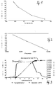
- the curve with the round measuring points shows an assumed 24-hour temperature curve of an airbag module installed in a steering wheel.
- the time of day is plotted on the abscissa and the temperature (in ° C) is plotted on the left ordinate.
- the temperature is below 30 ° C, then it rises rapidly in the sun for a parked motor vehicle, for example, and reaches a peak of over 80 ° C.
- the temperature does not drop again until 6 p.m.
- the exact course of the temperature - in 2 ° steps - and the associated time interval lengths can be found in the continuous numerical list according to FIG. 4 (columns 1 and 2).
- the aging curve numerically listed in FIG. 4 is also shown graphically in FIG. 3 (star-shaped curve points).
- the equivalent aging (in days) is plotted on the right ordinate above the time of day.
- the aging behavior of the gas generator i.e. of the explosive propellant for the airbag system.
- the specific aging behavior of the gas generator must be determined separately and the resulting constants fed into the computer. The calculations are based on the same formulas.
- climatic influences can have a major impact on the aging of airbag components.
- the invention offers the advantage of taking these influences into account in a calculable manner; This eliminates uncertainties and still protects economic aspects.
Landscapes
- Engineering & Computer Science (AREA)
- Mechanical Engineering (AREA)
- Physics & Mathematics (AREA)
- General Physics & Mathematics (AREA)
- Air Bags (AREA)
Claims (10)
- Système à airbag comprenant un dispositif pour déterminer et afficher la limite de vieillissement en fonction de la température d'une partie du système à airbag, comprenant une sonde de température pour détecter la température ou la température environnante de la partie du système à airbag, et comprenant un calculateur électronique, ledit calculateur étant réalisé afin recevoir en permanence un signal de mesure de la sonde de température, de déterminer en permanence du déroulement temporel du signal de mesure un vieillissement en fonction de la température de la partie du système à airbag, de comparer le vieillissement déterminé avec une limite de vieillissement prédéterminée de la partie du système d'airbag, et de fournir un signal de sortie au plus tard lorsque la limite de vieillissement est atteinte.
- Système à airbag selon la revendication 1, caractérisé en ce que le calculateur est réalisé de manière à recevoir et à traiter le signal de mesure de température également pendant des interruptions du fonctionnement du véhicule.
- Système à airbag selon l'une des revendications précédentes, caractérisé en ce que la sonde de température est réalisée de manière à détecter la température ou la température environnante du matériau de l'airbag.
- Système à airbag selon l'une des revendications précédentes, caractérisé en ce que le calculateur est réalisé de façon à pondérer et à additionner les longueurs des intervalles de la durée de vie de la partie du système à airbag en fonction du signal de mesure de température respectivement présent.
- Système à airbag selon la revendication 4, caractérisé en ce que le calculateur est réalisé de façon à déterminer les facteurs de pondération pour les intervalles de durée de vie en fonction du signal de mesure de température respectivement présent, à partir d'une courbe caractéristique, en particulier une formule de Arrhénius, dont les constantes sont déposées dans la mémoire du calculateur.
- Système à airbag selon la revendication 4, caractérisé en ce que les facteurs de pondération pour les intervalles de durée de vie sont déposés dans la mémoire du calculateur en tant que fonction du signal de mesure de température sous forme de tableau.
- Système à airbag selon l'une des revendications précédentes, caractérisé en ce que le calculateur est un ordinateur de bord pour le véhicule automobile.
- Système à airbag selon l'une des revendications précédentes, caractérisé en ce que le calculateur est réalisé de façon à délivrer un signal d'avertissement au plus tard lorsque la limite de durée de vie est atteinte.
- Système à airbag selon l'une des revendications précédentes, caractérisé en ce que le calculateur est réalisé de façon à délivrer un signal de blocage lorsque la limite de durée de vie est atteinte, ledit signal de blocage limitant le nombre de mises en marche postérieures du véhicule automobile et/ou sa vitesse.
- Système à airbag selon l'une des revendications précédentes, caractérisé en ce que la sonde de température est réalisée de façon à détecter la température ou la température ambiante d'un générateur de gaz pour l'airbag.
Applications Claiming Priority (2)
| Application Number | Priority Date | Filing Date | Title |
|---|---|---|---|
| DE4305172 | 1993-02-19 | ||
| DE4305172A DE4305172A1 (de) | 1993-02-19 | 1993-02-19 | Vorrichtung zur Überwachung eines sicherheitsrelevanten Elements eines Kraftfahrzeugs |
Publications (2)
| Publication Number | Publication Date |
|---|---|
| EP0612643A1 EP0612643A1 (fr) | 1994-08-31 |
| EP0612643B1 true EP0612643B1 (fr) | 1997-10-15 |
Family
ID=6480901
Family Applications (1)
| Application Number | Title | Priority Date | Filing Date |
|---|---|---|---|
| EP94102437A Expired - Lifetime EP0612643B1 (fr) | 1993-02-19 | 1994-02-17 | Dispositif de surveillance d'un élément de sécurité dans un véhicule automobile |
Country Status (2)
| Country | Link |
|---|---|
| EP (1) | EP0612643B1 (fr) |
| DE (2) | DE4305172A1 (fr) |
Cited By (1)
| Publication number | Priority date | Publication date | Assignee | Title |
|---|---|---|---|---|
| US11577678B1 (en) | 2021-12-13 | 2023-02-14 | Honda Motor Co., Ltd. | Air bag module, monitoring apparatus for supplemental restraint system, and method |
Families Citing this family (28)
| Publication number | Priority date | Publication date | Assignee | Title |
|---|---|---|---|---|
| DE19516481B4 (de) * | 1995-05-05 | 2007-01-04 | Robert Bosch Gmbh | Einrichtung zum Erfassen, Speichern und Ausgeben von Daten eines Steuergeräts in einem Kraftfahrzeug |
| DE19709445B4 (de) * | 1997-03-07 | 2004-01-15 | Volkswagen Ag | Vorrichtung und Verfahren zur Berechnung und Anzeige von Service-Intervallen |
| DE19854366C1 (de) * | 1998-11-25 | 2000-04-06 | Daimler Chrysler Ag | Verfahren zur Anpassung einer Auslöseschwelle von Insassenschutzeinrichtungen |
| DE10007308A1 (de) * | 2000-02-17 | 2001-08-23 | Bosch Gmbh Robert | Verfahren und Vorrichtung zur Ermittlung der verbleibenden Betriebsdauer eines Produktes |
| DE10060706A1 (de) * | 2000-12-07 | 2002-06-13 | Flowtec Ag | Verfahren und eine Vorrichtung zur System- und/oder Prozeßüberwachung |
| DE10126733A1 (de) * | 2001-05-31 | 2002-12-05 | Wilo Gmbh | Lebensdauerüberwachung an Umwälzpumpen |
| FR2827042B1 (fr) * | 2001-07-06 | 2003-10-03 | Renault | Procede d'evaluation de la duree de vie restante d'une courroie de transmission, et son dispositif de mise en oeuvre |
| DE10254819A1 (de) * | 2002-11-25 | 2004-06-09 | Robert Bosch Gmbh | Grenzlastabhängiges teilweises Abschalten einzelner Funktionen der Systemkomponenten eines Fahrzeugs |
| DE10257793A1 (de) * | 2002-12-11 | 2004-07-22 | Daimlerchrysler Ag | Modellbasierter Lebensdauerbeobachter |
| DE10310116A1 (de) * | 2003-03-06 | 2004-09-23 | Voith Turbo Gmbh & Co. Kg | Risikominimierung und Wartungsoptimierung durch Ermittlung von Schädigungsanteilen aus Betriebsdaten |
| DE102004024840B4 (de) * | 2004-05-14 | 2007-02-22 | Getrag Getriebe- Und Zahnradfabrik Hermann Hagenmeyer Gmbh & Cie Kg | Verfahren zum Steuern eines automatisierten Kraftfahrzeug-Antriebsstranges |
| DE102005021140B4 (de) * | 2005-05-06 | 2014-06-12 | Bayerische Motoren Werke Aktiengesellschaft | Verfahren zur Überwachung einer Auslöseschwelle und/oder eines Auslösezeitpunktes von Insassenschutzeinrichtungen |
| GB2430039B (en) * | 2005-09-07 | 2008-06-04 | Motorola Inc | Product age monitoring device and method of use of the device |
| DE102006057196A1 (de) * | 2006-12-05 | 2008-03-27 | Dräger Medical AG & Co. KG | Verfahren und Vorrichtung für die Ermittlung des hygienischen Zustandes eines Zusatzteiles für ein medizinisches Grundgerät |
| US8517760B2 (en) | 2007-08-20 | 2013-08-27 | Ford Global Technologies, Llc | Cord wrap and power plug receptacle arrangement for inflator |
| US8115615B2 (en) | 2007-09-08 | 2012-02-14 | Ford Global Technologies | Status indicator and reminder system for vehicle temporary mobility kit |
| US8146622B2 (en) | 2007-08-20 | 2012-04-03 | Ford Global Technologies, Llc | Switch and hose-valve connection arrangement for vehicle temporary mobility kit |
| US8981921B2 (en) | 2007-09-08 | 2015-03-17 | Ford Global Technologies, Llc | Status indicator and reminder system for vehicle temporary mobility kit |
| DE102010031135B4 (de) * | 2010-07-08 | 2015-01-22 | Micropatent B.V. | Überwachungsanordnung zum Überwachen einer Vorrichtung und Verfahren zum Überwachen einer Vorrichtung |
| DE102011006696A1 (de) | 2011-04-04 | 2012-10-04 | Zf Friedrichshafen Ag | Leistungselektronikbaugruppe |
| DE102011006695A1 (de) | 2011-04-04 | 2012-10-04 | Zf Friedrichshafen Ag | Baugruppe |
| DE202011110552U1 (de) * | 2011-10-26 | 2014-08-07 | TRUMPF Hüttinger GmbH + Co. KG | Elektrisches Gerät |
| DE102014211896A1 (de) * | 2014-06-20 | 2015-12-24 | Robert Bosch Gmbh | Verfahren zur Überwachung einer Fahrzeugsteuerung |
| US10296670B2 (en) | 2014-09-17 | 2019-05-21 | Infineon Technologies Ag | Age estimator for safety monitoring based on local detectors |
| JP6519432B2 (ja) | 2015-09-30 | 2019-05-29 | 豊田合成株式会社 | インフレーター |
| DE102017202506B4 (de) | 2017-02-16 | 2021-10-21 | Joyson Safety Systems Germany Gmbh | Gassackmodulanordnung und Verfahren zum Betreiben einer Gassackmodulanordnung |
| DE102018103008A1 (de) * | 2018-02-09 | 2019-08-14 | Trw Airbag Systems Gmbh | Verfahren zur überwachung eines sicherheitssystems in einem fahrzeug und überwachungssystem |
| DE102020118427A1 (de) | 2020-07-13 | 2022-01-13 | Endress+Hauser SE+Co. KG | Verfahren zur Ermittlung einer Restlebensdauer eines Dichtelements |
Family Cites Families (6)
| Publication number | Priority date | Publication date | Assignee | Title |
|---|---|---|---|---|
| DE2314954C3 (de) * | 1973-03-26 | 1982-08-26 | Brown, Boveri & Cie Ag, 6800 Mannheim | Anordnung zur laufenden Ermittlung und Überwachung der Lebensdauer von thermisch belasteten dickwandigen Bauelementen |
| US4733361A (en) * | 1980-09-03 | 1988-03-22 | Krieser Uri R | Life usage indicator |
| JPS58193914A (ja) * | 1982-04-09 | 1983-11-11 | Hitachi Constr Mach Co Ltd | 油圧システムの故障予知装置 |
| JPH0650340B2 (ja) * | 1986-04-14 | 1994-06-29 | 株式会社日立製作所 | 自動車用バツテリの寿命診断装置 |
| US5019760A (en) * | 1989-12-07 | 1991-05-28 | Electric Power Research Institute | Thermal life indicator |
| DE4110718A1 (de) * | 1991-04-03 | 1992-10-08 | Wolfang Dr Ing Kaufmann | Geraet zur erfassung und zaehlung des thermischen lebensalters von transformatoren |
-
1993
- 1993-02-19 DE DE4305172A patent/DE4305172A1/de not_active Withdrawn
-
1994
- 1994-02-17 EP EP94102437A patent/EP0612643B1/fr not_active Expired - Lifetime
- 1994-02-17 DE DE59404292T patent/DE59404292D1/de not_active Expired - Fee Related
Cited By (1)
| Publication number | Priority date | Publication date | Assignee | Title |
|---|---|---|---|---|
| US11577678B1 (en) | 2021-12-13 | 2023-02-14 | Honda Motor Co., Ltd. | Air bag module, monitoring apparatus for supplemental restraint system, and method |
Also Published As
| Publication number | Publication date |
|---|---|
| DE4305172A1 (de) | 1994-08-25 |
| DE59404292D1 (de) | 1997-11-20 |
| EP0612643A1 (fr) | 1994-08-31 |
Similar Documents
| Publication | Publication Date | Title |
|---|---|---|
| EP0612643B1 (fr) | Dispositif de surveillance d'un élément de sécurité dans un véhicule automobile | |
| DE10360582B4 (de) | Elektromechanische Lenkung eines Kraftfahrzeugs | |
| DE2314954B2 (de) | Anordnung zur laufenden Ermittlung und Überwachung der Lebensdauer von dickwandigen Bauelementen | |
| DE102018129119A1 (de) | Fahrwerksaktuator für eine Hinterachslenkung | |
| DE102013217340A1 (de) | Verfahren, Vorrichtung und System zur Überprüfung einer Vorrichtung für ein Fahrzeug zur Detektion eines Aufpralls | |
| DE10206474B4 (de) | Verfahren und Vorrichtung zur Erfassung der Reibung in einer elektrischen oder elektromechanischen Lenkvorrichtung eines Kraftfahrzeugs | |
| DE102019218638B3 (de) | Verfahren zur Überwachung einer Bremsstaubsammelvorrichtung, Überwachungssystem dazu sowie Kraftfahrzeug mit einem solchen | |
| DE102018100515A1 (de) | Verfahren zur beurteilung des zustandes eines treibriemens in einer elektrolenkung | |
| EP3841366B1 (fr) | Procédé et système pour la détermination directe d'un endommagement théorique d'au moins un organe d'un dispositif | |
| DE102022200268A1 (de) | Verfahren zum Betrieb eines Lenksystems | |
| DE102016114048A1 (de) | Verfahren und System zur Bestimmung eines Belastungszustandes eines, insbesondere landwirtschaftlichen, Fahrzeuges | |
| EP1566227A1 (fr) | Procédé de détection des défauts de planéité dans des bandes, en particulier des bandes en acier et des bandes métalliques et rouleau de détection de la planéité | |
| WO2013110113A2 (fr) | Transmission | |
| DE102021113325A1 (de) | Lastkraftfahrzeug mit Ladungsüberwachung | |
| EP2132716A1 (fr) | Système d'enregistrement de données et procédé de collecte de données au moyen d'un système d'enregistrement de données | |
| DE4024771A1 (de) | Verfahren und vorrichtung zur ueberwachung der temperatur der bremsbelagsaetze eines kraftfahrzeugs, insbesondere eines lastkraftwagens | |
| DE2948517A1 (de) | Vorrichtung und verfahren zur direkten messung der verlustleistung von zahnradgetrieben | |
| DE3828224A1 (de) | Anzeigevorrichtung fuer kraftfahrzeuge | |
| EP3612807B1 (fr) | Système de surveillance d'essieu d'un train roulant d'un véhicule utilitaire et utilisation d'un système de surveillance d'essieu | |
| AT522036B1 (de) | Verfahren zur Überwachung der Lebensdauer eines verbauten Wälzlagers | |
| EP3593099B1 (fr) | Procédé de fonctionnement d'un système de pesée embarqué dans un véhicule et système tachographe pourvu d'un système de pesée | |
| DE102019121497A1 (de) | Flurförderzeug und Verfahren zur Überwachung eines Flurförderzeugs | |
| DE102019100323A1 (de) | Diagnose eines Verdrehspiels im Antriebsstrang | |
| DE102019133870B4 (de) | Verfahren zum bestimmen der belastung eines lenksystems in einem fahrzeug | |
| DE102016221384A1 (de) | Verfahren und Vorrichtung zum Betreiben eines Sicherheitssystems eines Kraftfahrzeugs, Sicherheitssystem für ein Kraftfahrzeug |
Legal Events
| Date | Code | Title | Description |
|---|---|---|---|
| PUAI | Public reference made under article 153(3) epc to a published international application that has entered the european phase |
Free format text: ORIGINAL CODE: 0009012 |
|
| AK | Designated contracting states |
Kind code of ref document: A1 Designated state(s): DE ES FR GB IT SE |
|
| 17P | Request for examination filed |
Effective date: 19940916 |
|
| 17Q | First examination report despatched |
Effective date: 19941011 |
|
| GRAG | Despatch of communication of intention to grant |
Free format text: ORIGINAL CODE: EPIDOS AGRA |
|
| GRAH | Despatch of communication of intention to grant a patent |
Free format text: ORIGINAL CODE: EPIDOS IGRA |
|
| GRAH | Despatch of communication of intention to grant a patent |
Free format text: ORIGINAL CODE: EPIDOS IGRA |
|
| GRAA | (expected) grant |
Free format text: ORIGINAL CODE: 0009210 |
|
| AK | Designated contracting states |
Kind code of ref document: B1 Designated state(s): DE ES FR GB IT SE |
|
| PG25 | Lapsed in a contracting state [announced via postgrant information from national office to epo] |
Ref country code: IT Free format text: LAPSE BECAUSE OF FAILURE TO SUBMIT A TRANSLATION OF THE DESCRIPTION OR TO PAY THE FEE WITHIN THE PRE;WARNING: LAPSES OF ITALIAN PATENTS WITH EFFECTIVE DATE BEFORE 2007 MAY HAVE OCCURRED AT ANY TIME BEFORE 2007. THE CORRECT EFFECTIVE DATE MAY BE DIFFERENT FROM THE ONE RECORDED.SCRIBED TIME-LIMIT Effective date: 19971015 Ref country code: GB Free format text: LAPSE BECAUSE OF FAILURE TO SUBMIT A TRANSLATION OF THE DESCRIPTION OR TO PAY THE FEE WITHIN THE PRESCRIBED TIME-LIMIT Effective date: 19971015 Ref country code: FR Free format text: LAPSE BECAUSE OF FAILURE TO SUBMIT A TRANSLATION OF THE DESCRIPTION OR TO PAY THE FEE WITHIN THE PRESCRIBED TIME-LIMIT Effective date: 19971015 Ref country code: ES Free format text: THE PATENT HAS BEEN ANNULLED BY A DECISION OF A NATIONAL AUTHORITY Effective date: 19971015 |
|
| REF | Corresponds to: |
Ref document number: 59404292 Country of ref document: DE Date of ref document: 19971120 |
|
| PG25 | Lapsed in a contracting state [announced via postgrant information from national office to epo] |
Ref country code: SE Effective date: 19980115 |
|
| PGFP | Annual fee paid to national office [announced via postgrant information from national office to epo] |
Ref country code: DE Payment date: 19980223 Year of fee payment: 5 |
|
| EN | Fr: translation not filed | ||
| GBV | Gb: ep patent (uk) treated as always having been void in accordance with gb section 77(7)/1977 [no translation filed] |
Effective date: 19971015 |
|
| PLBE | No opposition filed within time limit |
Free format text: ORIGINAL CODE: 0009261 |
|
| STAA | Information on the status of an ep patent application or granted ep patent |
Free format text: STATUS: NO OPPOSITION FILED WITHIN TIME LIMIT |
|
| 26N | No opposition filed | ||
| PG25 | Lapsed in a contracting state [announced via postgrant information from national office to epo] |
Ref country code: DE Free format text: LAPSE BECAUSE OF NON-PAYMENT OF DUE FEES Effective date: 19991201 |