EP0612890A1 - Verbauvorrichtung für Gräben - Google Patents
Verbauvorrichtung für Gräben Download PDFInfo
- Publication number
- EP0612890A1 EP0612890A1 EP94890048A EP94890048A EP0612890A1 EP 0612890 A1 EP0612890 A1 EP 0612890A1 EP 94890048 A EP94890048 A EP 94890048A EP 94890048 A EP94890048 A EP 94890048A EP 0612890 A1 EP0612890 A1 EP 0612890A1
- Authority
- EP
- European Patent Office
- Prior art keywords
- plates
- shoring
- wedge
- plate
- connecting devices
- Prior art date
- Legal status (The legal status is an assumption and is not a legal conclusion. Google has not performed a legal analysis and makes no representation as to the accuracy of the status listed.)
- Granted
Links
- 230000006978 adaptation Effects 0.000 description 1
- 150000001875 compounds Chemical class 0.000 description 1
- 238000012986 modification Methods 0.000 description 1
- 230000004048 modification Effects 0.000 description 1
Images

Classifications
-
- E—FIXED CONSTRUCTIONS
- E02—HYDRAULIC ENGINEERING; FOUNDATIONS; SOIL SHIFTING
- E02D—FOUNDATIONS; EXCAVATIONS; EMBANKMENTS; UNDERGROUND OR UNDERWATER STRUCTURES
- E02D17/00—Excavations; Bordering of excavations; Making embankments
- E02D17/06—Foundation trenches ditches or narrow shafts
- E02D17/08—Bordering or stiffening the sides of ditches trenches or narrow shafts for foundations
Definitions
- the invention relates to a shoring device for trenches, with mutually opposing and spaced by spacing shoring plates, which have a wedge-shaped foot part on their lower edge and can be connected at their upper edge by means of connecting devices with extension plates.
- the invention has set itself the goal of designing a shoring device of the type mentioned at the outset in such a way that the disadvantages indicated are eliminated, so that universal use of the shoring panels is possible.
- This is achieved in that the wedge-shaped base parts are connected by means of connection devices to the shoring plates, which correspond to the connection devices serving to connect the extension plates.
- connection devices serving to connect the extension plates.
- Each of the shoring panels can be used as a base plate or as a top plate. If it is used as a base plate, the wedge-shaped base part is connected to it. Due to the equality of the connection devices, both a connection of two shoring panels to one another and the connection of a base part to a shoring panel are possible.
- the wedge-shaped foot part has at each of its two ends and the wedge opposite an upstanding plate which engage in pockets provided on the underside of the shoring plate and are secured by bolts.
- a reversal is also possible, so that the foot section - the one that is now open at the top - Has pockets and the shoring plate is provided with plates engaging in these pockets.
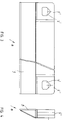
- FIG. 1 shows the (partial) front view of a shoring plate according to the invention which can be used both as a bottom plate and as a top plate;
- Fig. 2 is a side view of the plate of Fig. 1;
- Fig. 3 in an enlarged scale compared to Fig. 1 and Fig. 2, the front view of a foot part according to the invention and
- Fig. 4 the side view.
- a shoring plate 1 has receptacles 2 on the side for inserting rectangular struts, which, as spreaders, keep mutually opposing shoring plates 1 at a distance from one another.
- the receptacles 2 are arranged on both sides of the shoring plate 1, for reasons of space only one side of the symmetrically designed shoring plate 1 is shown in FIG. 1.
- Two plates 3 protrude from the underside of the shoring plate 1 - again from both sides - through which two pockets 4 open at the bottom are formed. From the top of the shoring plate 1, plates 5 protrude upwards such that these plates 5 fit into the pockets 4 of a shoring plate, not shown, arranged above the shoring plate 1 shown.
- the plates 3 of the pockets 4 are provided with holes 6 and the plates 5 have openings 7, the inner contour of which tapers conically upwards.
- a bolt can be inserted through the bores 6 and the openings 7, which connects the two shoring panels to one another, centering being carried out by the conical shape of the openings 7 extending upwards.
- the upper side of the foot part 8 corresponds exactly to the upper side of the shoring plate 1, that is to say there are two upwardly projecting plates 5 'which are provided with openings 7'.
- the size and shape of the plates 5 'and openings 7' correspond to the size and shape of the plates 5 and openings 7 of the shoring plate 1.
- the foot part 8 according to FIGS. 3 and 4 can therefore be connected at the bottom to the lining plate 1 according to FIGS. 1 and 2 by inserting the plates 5 'of the foot part 8 into the pockets 4 of the lining plate 1 will. After inserting bolts through the bores 6 or recesses 7 ', the foot part 8 is firmly connected to the mounting plate 1 and it is thus a bottom plate from the mounting plate 1 according to FIGS. 1 and 2, which in the illustrated state represents an extension plate been made.
Landscapes
- Engineering & Computer Science (AREA)
- Mining & Mineral Resources (AREA)
- Life Sciences & Earth Sciences (AREA)
- General Life Sciences & Earth Sciences (AREA)
- Paleontology (AREA)
- Civil Engineering (AREA)
- General Engineering & Computer Science (AREA)
- Structural Engineering (AREA)
- Road Paving Structures (AREA)
Abstract
Description
- Die Erfindung bezieht sich auf eine Verbauvorrichtung für Gräben, mit paarweise einander gegenüberstehenden und durch Spreizen im Abstand gehaltenen Verbauplatten, die an ihrer Unterkante einen keilförmigen Fußteil aufweisen und an ihrer Oberkante mittels Anschlußeinrichtungen mit Aufstockplatten verbindbar sind.
- Derartige Verbauvorrichtungen haben sich in der Praxis bestens bewährt, weil sie durch die Möglichkeit einer Vergrößerung der Höhe des Verbaues mittels der Aufstockplatten eine Anpassung an die Höhe des zu verbauenden Grabens erlauben. Nachteilig ist allerdings, daß beim Verbau von weniger tiefen Gräben die Aufstockplatten nicht eingesetzt werden können, nutzlos im Depot des Unternehmers stehen und somit ein totes Kapital bilden.
- Die Erfindung hat es sich zum Ziel gesetzt, eine Verbauvorrichtung der eingangs genannten Art so auszubilden, daß die aufgezeigten Nachteile beseitigt werden, daß demnach ein universeller Einsatz der Verbauplatten möglich ist. Erreicht wird dies dadurch, daß die keilförmigen Fußteile mittels Anschlußeinrichtungen mit den Verbauplatten verbunden sind, die den der Verbindung der Aufstockplatten dienenden Anschlußeinrichtungen entsprechen. Bei einer erfindungsgemäßen Verbauvorrichtung gibt es demnach nur eine Art von Verbauplatten. Jede der Verbauplatten kann als Unterplatte oder als Aufstockplatte eingesetzt werden. Wird sie als Unterplatte verwendet, wird der keilförmige Unterteil mit ihr verbunden. Zufolge der Gleichheit der Anschlußeinrichtungen ist sowohl eine Verbindung zweier Verbauplatten miteinander als auch die Verbindung eines Fußteiles mit einer Verbauplatte möglich.
- Bei in lotrechten Stützen geführten Verbauplatten wurde zwar schon vorgeschlagen, den Fußteil lösbar mit einer Einzelplatte zu verbinden. Dadurch kann jedoch das der Erfindung zugrunde liegende Problem nicht gelöst werden.
- Bei einer bevorzugten Ausführungsform der Erfindung weist der keilförmige Fußteil an seinen beiden Enden und dem Keil gegenüberliegend je eine nach oben ragende Platte auf, die in an der Unterseite der Verbauplatte vorgesehene Taschen eingreifen und durch Bolzen gesichert sind. Es ist aber auch eine Umkehrung möglich, sodaß der Fußteil - die nun nach oben offenen - Taschen aufweist und die Verbauplatte mit in diese Taschen eingreifenden Platten versehen ist.
- Nachstehend ist die Erfindung anhand eines in den Zeichnungen dargestellten Ausführungsbeispieles näher beschrieben, ohne jedoch auf dieses Beispiel beschränkt zu sein. Dabei zeigen: Fig. 1 die (teilweise) Vorderansicht einer erfindungsgemäßen Verbauplatte, die sowohl als Unterplatte als auch als Aufstockplatte eingesetzt werden kann; Fig. 2 eine Seitenansicht der Platte nach Fig. 1; Fig. 3 in gegenüber den Fig. 1 und Fig. 2 vergrößertem Maßstab die Vorderansicht auf einen Fußteil nach der Erfindung und Fig. 4 dessen Seitenansicht.
- Gemäß den Fig. 1 und 2 weist eine Verbauplatte 1 seitlich Aufnahmen 2 zum Einsetzen von Rechteckstreben auf, die als Spreizen einander gegenüberstehende Verbauplatten 1 im Abstand voneinander halten. Die Aufnahmen 2 sind auf beiden Seiten der Verbauplatte 1 angeordnet, aus Platzgründen ist in Fig. 1 nur eine Seite der symmetrisch ausgebildeten Verbauplatte 1 gezeigt.
- Von der Unterseite der Verbauplatte 1 ragen - wieder von beiden Seiten - je zwei Platten 3 nach unten, durch die zwei nach unten offene Taschen 4 gebildet werden. Von der Oberseite der Verbauplatte 1 ragen Platten 5 nach oben, derart, daß diese Platten 5 in die Taschen 4 einer über der gezeichneten Verbauplatte 1 angeordneten, nicht gezeichneten Verbauplatte passen.
- Die Platten 3 der Taschen 4 sind mit Bohrungen 6 versehen und die Platten 5 weisen Öffnungen 7 auf, deren innerer Umriß nach oben zu konisch zuläuft. Bei übereinander angeordneten Verbauplatten kann daher durch die Bohrungen 6 und die Öffnungen 7 ein Bolzen gesteckt werden, der die beiden Verbauplatten miteinander verbindet, wobei durch die nach oben hin verlaufende konische Form der Öffnungen 7 eine Zentrierung erfolgt.
- Der Fußteil nach den Fig. 3 und 4 weist einen unteren Keil 9 auf, der aus miteinander verschweißten Platten gebildet ist. Die Oberseite des Fußteiles 8 entspricht genau der Oberseite der Verbauplatte 1, das heißt es sind zwei nach oben ragende Platten 5' angeordnet, die mit Öffnungen 7' versehen sind. Größe und Form der Platten 5' und Öffnungen 7' entsprechen der Größe und Form der Platten 5 und Öffnungen 7 der Verbauplatte 1.
- Der Fußteil 8 gemäß den Fig. 3 und 4 kann daher unten mit der Verbauplatte 1 nach den Fig. 1 und 2 dadurch verbunden werden, daß die Platten 5' des Fußteiles 8 in die Taschen 4 der Verbauplatte 1 eingeführt werden. Nach dem Durchstecken von Bolzen durch die Bohrungen 6 bzw. Ausnehmungen 7' ist der Fußteil 8 mit der Verbauplatte 1 fest verbunden und es ist damit aus der Verbauplatte 1 nach den Fig. 1 und 2, die im gezeichneten Zustand eine Aufstockplatte darstellt, eine Unterplatte hergestellt worden.
- Im Rahmen der Erfindung sind zahlreiche Abänderungen möglich. So könnten statt der durch Platten 3,4 hergestellten Anschlußeinrichtungen auch solche mittels kegeliger oder zylindrischer Zapfen, die in entsprechende Bohrungen eingreifen, verwirklicht werden. Überhaupt sind alle bekannte Verbindungen im Rahmen der Erfindung anwendbar.
Claims (2)
- Verbauvorrichtung für Gräben, mit paarweise einander gegenüberstehenden und durch Spreizen im Abstand gehaltenen Verbauplatten (1), die an ihrer Unterkante einen keilförmigen Fußteil (8) aufweisen und an ihrer Oberkante mittels Anschlußeinrichtungen (4,5') mit Aufstockplatten (1) verbindbar sind, dadurch gekennzeichnet, daß die keilförmigen Fußteile (8) mittels Anschlußeinrichtungen (4,5') mit den Verbauplatten (1) verbunden sind, die den der Verbindung der Aufstockplatten dienenden Anschlußeinrichtungen (4,5) entsprechen.
- Verbauvorrichtung für Gräben nach Anspruch 1, dadurch gekennzeichnet, daß der keilförmige Fußteil (8) an seinen beiden Enden und dem Keil (9) gegenüberliegend je eine nach oben ragende Platte (5') aufweist, die in an der Unterseite der Verbauplatte (1) vorgesehene Taschen (4) eingreifen und durch Bolzen gesichert sind.
Applications Claiming Priority (2)
| Application Number | Priority Date | Filing Date | Title |
|---|---|---|---|
| AT351/93 | 1993-02-23 | ||
| AT35193A AT399524B (de) | 1993-02-23 | 1993-02-23 | Verbauvorrichtung für gräben |
Publications (2)
| Publication Number | Publication Date |
|---|---|
| EP0612890A1 true EP0612890A1 (de) | 1994-08-31 |
| EP0612890B1 EP0612890B1 (de) | 1997-05-02 |
Family
ID=3488315
Family Applications (1)
| Application Number | Title | Priority Date | Filing Date |
|---|---|---|---|
| EP94890048A Expired - Lifetime EP0612890B1 (de) | 1993-02-23 | 1994-02-23 | Verbauvorrichtung für Gräben |
Country Status (3)
| Country | Link |
|---|---|
| EP (1) | EP0612890B1 (de) |
| AT (1) | AT399524B (de) |
| DE (1) | DE59402571D1 (de) |
Citations (2)
| Publication number | Priority date | Publication date | Assignee | Title |
|---|---|---|---|---|
| EP0111289A2 (de) * | 1982-12-13 | 1984-06-20 | Josef Krings | Verbauplatte. |
| EP0396420A2 (de) * | 1989-05-03 | 1990-11-07 | Mabey Hire Limited | Verbaukorbschalung |
Family Cites Families (2)
| Publication number | Priority date | Publication date | Assignee | Title |
|---|---|---|---|---|
| GB2053314A (en) * | 1979-07-02 | 1981-02-04 | Osato K | Trench shoring |
| GB2094373B (en) * | 1981-03-07 | 1984-08-01 | Morris Alan | Trench shoring |
-
1993
- 1993-02-23 AT AT35193A patent/AT399524B/de not_active IP Right Cessation
-
1994
- 1994-02-23 DE DE59402571T patent/DE59402571D1/de not_active Expired - Fee Related
- 1994-02-23 EP EP94890048A patent/EP0612890B1/de not_active Expired - Lifetime
Patent Citations (2)
| Publication number | Priority date | Publication date | Assignee | Title |
|---|---|---|---|---|
| EP0111289A2 (de) * | 1982-12-13 | 1984-06-20 | Josef Krings | Verbauplatte. |
| EP0396420A2 (de) * | 1989-05-03 | 1990-11-07 | Mabey Hire Limited | Verbaukorbschalung |
Also Published As
| Publication number | Publication date |
|---|---|
| ATA35193A (de) | 1994-10-15 |
| EP0612890B1 (de) | 1997-05-02 |
| AT399524B (de) | 1995-05-26 |
| DE59402571D1 (de) | 1997-06-05 |
Similar Documents
| Publication | Publication Date | Title |
|---|---|---|
| DE69605905T2 (de) | Befestigungsanordnung für eine hintere abdeckplatte eines fahrzeugs | |
| DE2243797A1 (de) | Zusammenlegbarer tisch | |
| DE2757450C2 (de) | Vorrichtung zum Verbinden zweier Schalungselemente | |
| DE2807061A1 (de) | Aus einzeltasten zusammensetzbare tastatur | |
| EP0427012B1 (de) | Säulenführungsgestell | |
| EP0612890B1 (de) | Verbauvorrichtung für Gräben | |
| DE3423721A1 (de) | Schaltschrank, insbesondere reihenschaltschrank | |
| EP0317937B1 (de) | Schalungsvorrichtung | |
| DE69500153T2 (de) | Strukturelement für einen Gestellrahmen eines Schaltschranks | |
| DE3128376A1 (de) | Module gebaeudestruktur | |
| EP0474967A1 (de) | Ski | |
| DE7919186U1 (de) | Kupplung zum Zusammenkuppeln fluchtend verlaufender Kabelrinnen | |
| EP0380995B1 (de) | Tischsystem | |
| EP1406361B1 (de) | Montageelement für Geräteeinbaukanäle | |
| DE8622358U1 (de) | Vorrichtung zum Verbinden zweier Schalungselemente | |
| DE2435748C2 (de) | Aufgeständerter Fußboden | |
| DE3725340C2 (de) | ||
| DE29707193U1 (de) | Rasengitterplatte | |
| DE3119023A1 (de) | Betonschalung | |
| DE19805749A1 (de) | Zusammensteckbarer Stuhl aus vier Teilen | |
| AT320244B (de) | Zarge | |
| DE2061275A1 (de) | Zusammensetzbarer Auffangbehaelter | |
| EP1043509A2 (de) | Gelenk zur Bildung eines Rahmens | |
| DE7632470U1 (de) | Fussgestell eines sitzmoebels | |
| DE7601140U (de) | Gerätegehäuse mit senkrecht aufeinanderstoßenden Wänden |
Legal Events
| Date | Code | Title | Description |
|---|---|---|---|
| PUAI | Public reference made under article 153(3) epc to a published international application that has entered the european phase |
Free format text: ORIGINAL CODE: 0009012 |
|
| AK | Designated contracting states |
Kind code of ref document: A1 Designated state(s): CH DE FR GB IT LI |
|
| 17P | Request for examination filed |
Effective date: 19940905 |
|
| 17Q | First examination report despatched |
Effective date: 19950919 |
|
| GRAG | Despatch of communication of intention to grant |
Free format text: ORIGINAL CODE: EPIDOS AGRA |
|
| GRAH | Despatch of communication of intention to grant a patent |
Free format text: ORIGINAL CODE: EPIDOS IGRA |
|
| GRAH | Despatch of communication of intention to grant a patent |
Free format text: ORIGINAL CODE: EPIDOS IGRA |
|
| GRAA | (expected) grant |
Free format text: ORIGINAL CODE: 0009210 |
|
| AK | Designated contracting states |
Kind code of ref document: B1 Designated state(s): CH DE FR GB IT LI |
|
| PG25 | Lapsed in a contracting state [announced via postgrant information from national office to epo] |
Ref country code: IT Free format text: LAPSE BECAUSE OF FAILURE TO SUBMIT A TRANSLATION OF THE DESCRIPTION OR TO PAY THE FEE WITHIN THE PRE;WARNING: LAPSES OF ITALIAN PATENTS WITH EFFECTIVE DATE BEFORE 2007 MAY HAVE OCCURRED AT ANY TIME BEFORE 2007. THE CORRECT EFFECTIVE DATE MAY BE DIFFERENT FROM THE ONE RECORDED.SCRIBED TIME-LIMIT Effective date: 19970502 Ref country code: GB Effective date: 19970502 Ref country code: FR Effective date: 19970502 |
|
| REG | Reference to a national code |
Ref country code: CH Ref legal event code: EP |
|
| REF | Corresponds to: |
Ref document number: 59402571 Country of ref document: DE Date of ref document: 19970605 |
|
| EN | Fr: translation not filed | ||
| GBV | Gb: ep patent (uk) treated as always having been void in accordance with gb section 77(7)/1977 [no translation filed] |
Effective date: 19970502 |
|
| PG25 | Lapsed in a contracting state [announced via postgrant information from national office to epo] |
Ref country code: LI Free format text: LAPSE BECAUSE OF NON-PAYMENT OF DUE FEES Effective date: 19980228 Ref country code: CH Free format text: LAPSE BECAUSE OF NON-PAYMENT OF DUE FEES Effective date: 19980228 |
|
| PLBE | No opposition filed within time limit |
Free format text: ORIGINAL CODE: 0009261 |
|
| STAA | Information on the status of an ep patent application or granted ep patent |
Free format text: STATUS: NO OPPOSITION FILED WITHIN TIME LIMIT |
|
| 26N | No opposition filed | ||
| REG | Reference to a national code |
Ref country code: CH Ref legal event code: PL |
|
| PG25 | Lapsed in a contracting state [announced via postgrant information from national office to epo] |
Ref country code: DE Free format text: LAPSE BECAUSE OF NON-PAYMENT OF DUE FEES Effective date: 19981201 |