EP0612905A2 - Charnière pour portes, fenêtres ou similaires - Google Patents
Charnière pour portes, fenêtres ou similaires Download PDFInfo
- Publication number
- EP0612905A2 EP0612905A2 EP94101165A EP94101165A EP0612905A2 EP 0612905 A2 EP0612905 A2 EP 0612905A2 EP 94101165 A EP94101165 A EP 94101165A EP 94101165 A EP94101165 A EP 94101165A EP 0612905 A2 EP0612905 A2 EP 0612905A2
- Authority
- EP
- European Patent Office
- Prior art keywords
- hinge
- cover strip
- hinge part
- wing
- frame
- Prior art date
- Legal status (The legal status is an assumption and is not a legal conclusion. Google has not performed a legal analysis and makes no representation as to the accuracy of the status listed.)
- Granted
Links
Images

Classifications
-
- E—FIXED CONSTRUCTIONS
- E05—LOCKS; KEYS; WINDOW OR DOOR FITTINGS; SAFES
- E05D—HINGES OR SUSPENSION DEVICES FOR DOORS, WINDOWS OR WINGS
- E05D5/00—Construction of single parts, e.g. the parts for attachment
- E05D5/10—Pins, sockets or sleeves; Removable pins
- E05D5/14—Construction of sockets or sleeves
-
- E—FIXED CONSTRUCTIONS
- E05—LOCKS; KEYS; WINDOW OR DOOR FITTINGS; SAFES
- E05D—HINGES OR SUSPENSION DEVICES FOR DOORS, WINDOWS OR WINGS
- E05D5/00—Construction of single parts, e.g. the parts for attachment
- E05D5/02—Parts for attachment, e.g. flaps
- E05D5/04—Flat flaps
-
- E—FIXED CONSTRUCTIONS
- E05—LOCKS; KEYS; WINDOW OR DOOR FITTINGS; SAFES
- E05D—HINGES OR SUSPENSION DEVICES FOR DOORS, WINDOWS OR WINGS
- E05D5/00—Construction of single parts, e.g. the parts for attachment
- E05D5/10—Pins, sockets or sleeves; Removable pins
-
- E—FIXED CONSTRUCTIONS
- E05—LOCKS; KEYS; WINDOW OR DOOR FITTINGS; SAFES
- E05D—HINGES OR SUSPENSION DEVICES FOR DOORS, WINDOWS OR WINGS
- E05D7/00—Hinges or pivots of special construction
- E05D7/0009—Adjustable hinges
- E05D7/0018—Adjustable hinges at the hinge axis
-
- E—FIXED CONSTRUCTIONS
- E05—LOCKS; KEYS; WINDOW OR DOOR FITTINGS; SAFES
- E05D—HINGES OR SUSPENSION DEVICES FOR DOORS, WINDOWS OR WINGS
- E05D7/00—Hinges or pivots of special construction
- E05D7/0009—Adjustable hinges
- E05D7/0018—Adjustable hinges at the hinge axis
- E05D7/0027—Adjustable hinges at the hinge axis in an axial direction
-
- E—FIXED CONSTRUCTIONS
- E05—LOCKS; KEYS; WINDOW OR DOOR FITTINGS; SAFES
- E05D—HINGES OR SUSPENSION DEVICES FOR DOORS, WINDOWS OR WINGS
- E05D11/00—Additional features or accessories of hinges
- E05D11/0054—Covers, e.g. for protection
-
- E—FIXED CONSTRUCTIONS
- E05—LOCKS; KEYS; WINDOW OR DOOR FITTINGS; SAFES
- E05D—HINGES OR SUSPENSION DEVICES FOR DOORS, WINDOWS OR WINGS
- E05D3/00—Hinges with pins
- E05D3/02—Hinges with pins with one pin
- E05D2003/025—Hinges with pins with one pin having three knuckles
-
- E—FIXED CONSTRUCTIONS
- E05—LOCKS; KEYS; WINDOW OR DOOR FITTINGS; SAFES
- E05D—HINGES OR SUSPENSION DEVICES FOR DOORS, WINDOWS OR WINGS
- E05D3/00—Hinges with pins
- E05D3/02—Hinges with pins with one pin
- E05D2003/025—Hinges with pins with one pin having three knuckles
- E05D2003/027—Hinges with pins with one pin having three knuckles the end knuckles being mutually connected
-
- E—FIXED CONSTRUCTIONS
- E05—LOCKS; KEYS; WINDOW OR DOOR FITTINGS; SAFES
- E05D—HINGES OR SUSPENSION DEVICES FOR DOORS, WINDOWS OR WINGS
- E05D7/00—Hinges or pivots of special construction
- E05D7/10—Hinges or pivots of special construction to allow easy separation or connection of the parts at the hinge axis
- E05D7/1005—Hinges or pivots of special construction to allow easy separation or connection of the parts at the hinge axis by axially moving free pins, balls or sockets
- E05D2007/1038—Hinges or pivots of special construction to allow easy separation or connection of the parts at the hinge axis by axially moving free pins, balls or sockets by axially moving free sockets
-
- E—FIXED CONSTRUCTIONS
- E05—LOCKS; KEYS; WINDOW OR DOOR FITTINGS; SAFES
- E05D—HINGES OR SUSPENSION DEVICES FOR DOORS, WINDOWS OR WINGS
- E05D7/00—Hinges or pivots of special construction
- E05D7/10—Hinges or pivots of special construction to allow easy separation or connection of the parts at the hinge axis
- E05D7/1005—Hinges or pivots of special construction to allow easy separation or connection of the parts at the hinge axis by axially moving free pins, balls or sockets
-
- E—FIXED CONSTRUCTIONS
- E05—LOCKS; KEYS; WINDOW OR DOOR FITTINGS; SAFES
- E05Y—INDEXING SCHEME ASSOCIATED WITH SUBCLASSES E05D AND E05F, RELATING TO CONSTRUCTION ELEMENTS, ELECTRIC CONTROL, POWER SUPPLY, POWER SIGNAL OR TRANSMISSION, USER INTERFACES, MOUNTING OR COUPLING, DETAILS, ACCESSORIES, AUXILIARY OPERATIONS NOT OTHERWISE PROVIDED FOR, APPLICATION THEREOF
- E05Y2800/00—Details, accessories and auxiliary operations not otherwise provided for
- E05Y2800/20—Combinations of elements
- E05Y2800/205—Combinations of elements forming a unit
-
- E—FIXED CONSTRUCTIONS
- E05—LOCKS; KEYS; WINDOW OR DOOR FITTINGS; SAFES
- E05Y—INDEXING SCHEME ASSOCIATED WITH SUBCLASSES E05D AND E05F, RELATING TO CONSTRUCTION ELEMENTS, ELECTRIC CONTROL, POWER SUPPLY, POWER SIGNAL OR TRANSMISSION, USER INTERFACES, MOUNTING OR COUPLING, DETAILS, ACCESSORIES, AUXILIARY OPERATIONS NOT OTHERWISE PROVIDED FOR, APPLICATION THEREOF
- E05Y2900/00—Application of doors, windows, wings or fittings thereof
- E05Y2900/10—Application of doors, windows, wings or fittings thereof for buildings or parts thereof
- E05Y2900/13—Type of wing
- E05Y2900/132—Doors
-
- E—FIXED CONSTRUCTIONS
- E05—LOCKS; KEYS; WINDOW OR DOOR FITTINGS; SAFES
- E05Y—INDEXING SCHEME ASSOCIATED WITH SUBCLASSES E05D AND E05F, RELATING TO CONSTRUCTION ELEMENTS, ELECTRIC CONTROL, POWER SUPPLY, POWER SIGNAL OR TRANSMISSION, USER INTERFACES, MOUNTING OR COUPLING, DETAILS, ACCESSORIES, AUXILIARY OPERATIONS NOT OTHERWISE PROVIDED FOR, APPLICATION THEREOF
- E05Y2900/00—Application of doors, windows, wings or fittings thereof
- E05Y2900/10—Application of doors, windows, wings or fittings thereof for buildings or parts thereof
- E05Y2900/13—Type of wing
- E05Y2900/148—Windows
Definitions
- the invention relates to a volume of the type corresponding to the preamble of claim 1.
- Such a band is known from DE-GM 90 06 439.
- the height of the sash can be adjusted by means of a screw element which is arranged in a bore in the frame hinge part which is coaxial with the hinge pin axis and which, when it rotates, lifts the hinge pin or the hinge sleeve receiving it.
- the cover strip hides the areas of the frame hinge part and the sash hinge part that are adjacent to one another, so that the mutually facing edges are no longer visible and can no longer give off a scale perceptible to the naked eye for the set height of the sash.
- the height of the wing hinge part above the frame hinge part is objectively different, which can easily be determined by a measurement.
- the lower limit of the frame hinge part and the upper limit of the wing hinge part form very widely spaced reference points, the relative position of which is barely perceptible to the naked eye.
- the cover strip is connected to the frame hinge part in the axial direction of the hinge pin, so that it is fixed and the frame hinge part moves up and down relative to the cover strip.
- the cover strip is in constant contact with the wing hinge part in the axial direction of the hinge pin and follows its adjustment movement, wherein it is displaced vertically relative to the frame hinge part.
- the cover strip can be formed as a collar which sits on the outer edge of an overlying the upper side of the frame hinge part of a ring bolt bush arranged in the frame hinge part.
- the hinge pin bushing is designed as a type of hat which overlaps the frame hinge part with the brim.
- the ring part formed by the brim transmits the forces introduced by the wing hinge part to the frame hinge part.
- the ring part goes radially (with respect to the Hinge pin) up to the area of the outer edge of the hinge parts and is connected to the collar there.
- a first possibility is that the cover strip is integrally formed on the hinge pin bush.
- hinge pin bushing consists of a suitable plastic and is subject to a corresponding molding process, it is expedient to include the formation of the cover strip in this case.
- the alternative according to claim 6 is to design the cover strip as a separate molded part.
- this molded part can be designed according to claim 7.
- the shorter leg is used to fix the molded part, while the longer leg forms the cover strip.
- a particularly advantageous embodiment is the subject of claim 8 and can be designed according to claim 9 by a lock, which can include inserting the U-shaped molded part from the front and fixing it in the final position reached, for example by snapping in a suitable latching device.
- the invention is for both two-piece and three-piece tapes, i.e. so-called hinge straps, suitable (claim 11).
- the lower cover strip follows the movement of the wing hinge part during the adjustment.
- top cover strip a special tracking device according to claim 12 to avoid gaping the gap at the lower edge of the upper cover strip if the upper hinge pin bushing does not come along when lowering.
- a simple embodiment is a spring that constantly depresses the upper hinge pin bushing (claim 14).
- the movement of the cover strip can also be coupled to the movement of the hinge pin, which moves along with the adjustment stroke.
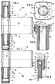
- hinge band which is attached to the front surface 38 of the fixed frame 1, which is only indicated by dash-dotted lines in the figures, and to the front surface 39 of the wing 2 attached wing hinge part 20, which are pivotable against each other about a hinge axis 9 formed by a hinge pin 8 (FIG. 4).
- the frame hinge part is fastened to the frame 1 by screws 3 and fixing pins 4, the sash hinge part 20 by screws 5 and fixing pins 6 to the wing 2.
- the frame 2 and the wing 1 do not abut each other directly, but usually form a fold with a so-called shadow groove 7 the visible side.
- the frame hinge part 10 comprises a lower hinge part 11 and an upper hinge part 12, between which the hinge part 13 of the wing hinge part 20 engages.
- the hinge pin 8 extends vertically through the hinge parts 11, 12, 13.
- the sash hinge part 20 is arranged in the hinge hinge part 10 to be height-adjustable by a certain distance in the direction of the arrow 14 in order to be able to adjust the position of the sash in the frame.
- the gaps 26 change between the upper limit 15 and the hinge part 11 and the lower limit 16 of the hinge part 13 and the upper limit 17 of the hinge part 13 and the lower limit 18 of the hinge part 12 (see FIG. 2).
- cover strips 50 which in the Embodiment with one edge 51 on the horizontal and horizontal upper and lower boundaries 16, 17 of the wing hinge part 20 and move up and down with it.
- the training in detail is shown in Fig. 4.
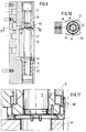
- the hinge pin 8 sits in each of the hinge parts 11, 12 in a hinge pin bushing 30, which in turn is received in a corresponding recess 19 of the hinge parts 11, 12.
- the recess 19 is formed as a threaded bore 21 into which a nut-like screw element 22 can be screwed, which can be rotated by a turning tool engaging in a hexagon socket 23.
- the lower hinge pin bush 30 When screwing in, the lower hinge pin bush 30 according to FIG. 4 lifts the wing hinge part 20. This leads to the adjustment.
- the lower hinge pin bushing 30 has, at the upper edge, as shown in FIG. 4, facing the lower boundary 16 of the wing hinge part 20, a collar part 24 projecting radially outwards, which ends with the upper end of the hinge pin bushing 30.
- the cover strip 50 extends from its edge 51 resting on the wing hinge in the form of a collar 25 parallel to the hinge pin axis 9 against the main part of the hinge pin bushing 30 (see also FIG. 5).
- a circumferential groove 28 is thus formed which is open towards the end of the hinge pin bush 30 remote from the ring part 24 and which receives the edge of the hinge part 11 or 12 there in such a way that an axial movement of the parts 30 and 11, 12 relative to one another is possible.
- the collar 25 is thin-walled, since it has only an optical function and does not have to transmit any forces. It is only supposed to be the gap 26 cover. In any case, the cover strip 50 lies in the area of its edge 52 (FIG.
- FIG. 6 shows where this floor plan is approximately square with slightly convex rounded sides.
- the cover strip 50 and the collar 25 are only present on the visible sides according to FIGS. 5 and 6, but not on the rear side 27.
- a same hinge pin bushing 30 is provided, which is only reversed, i.e. is arranged in mirror image to the horizontal central plane 39 of the band 100 and in which the collar 25 forming the cover strip 50 'extends upwards from the ring part 24. Otherwise the function is the same.
- the lower hinge pin bushing 30 is carried along by the screw element 21 and is always in contact with the lower boundary surface 16 of the wing hinge part 20.
- a helical compression spring 31 which is put under tension by a cover disk 29 pressed into the recess 19 of the hinge part 12 and is only indicated by dash-dotted lines in FIG. 4 and which holds the hinge pin bushing 30 or the cover strip 50 '' in contact with the upper boundary surface 17 of the wing hinge part 20.
- FIGS. 9 to 11 Another embodiment of a device which keeps the upper cover strip 50 'in contact with the upper boundary surface 17 of the sash hinge part 20 even when the sash hinge part 20 is lowered is shown in FIGS. 9 to 11, in which the hinge pin bush 30 of FIG. 5 and 6 is used.
- the hinge pin bushing 30 has at its end adjacent to the collar 25 six notches 40 which are evenly distributed over the circumference and extend to a certain depth, are divided by the six segments 41, 42 of equal size in the circumferential direction, which alternately follow one another in the circumferential direction.
- the segments 42 Just as deeply extending recesses 43 are arranged behind the segments 42, so that the segments 42 form all-round free-standing axial tongues which, on the side facing the hinge pin, have a slightly radially projecting hook-like projections 44 at their free end against the inside of the hinge pin bushing 30. Thanks to the elasticity of the tongue-like segments 42, they can be pressed backwards against the recess 43 by the radial extension of the projections 44.
- the hinge pin 8 has an all-round groove 45 into which the projection 44 can engage when the hinge pin bush 30 is on the upper edge 46 of the eccentric sleeve 47 seated in the wing hinge part 20 or the lower edge of the upper cover strip 50 ' abut the upper boundary surface 17 of the wing hinge part 20.
- the projection 44 hooks in this position in the all-round groove 45, so that the hinge pin bushing 30 is carried along during the up and down movements occurring during the adjustment.
- the cover strip 50 is formed in one piece with the hinge pin bush 30, in the two-part hinge 200 of FIGS. 7 and 8 a separate molded part 35 is provided to form the cover strip 50.
- the hinge pin bushing 30 again has a ring part 24 projecting radially outwards from its upper edge, which has a recess 32 along its edge shaped in accordance with the outline of the hinge part 13, into which a shorter leg 33 of the shape formed by an angular profile at a right angle partially engages 35, the longer leg 34 forms the cover strip 50 and tightly encloses the upper edge of the hinge part 11 of the frame hinge part 10 in the manner shown in FIG. 8.
- the molded part 35 Since the adjustment or lifting of the wing hinge 20 takes place via the screw member 22 while lifting the hinge pin bushing 30, the upper edge of the molded part 35 always remains in contact with the lower boundary 16 of the wing hinge part 20.
- the molded part 35 has a U-shaped outline, 7 and 8 so that it can be inserted into the groove 32 from the front with the shorter leg 33. Appropriate shaping will lock into the final position.
- the dimensioning is such that the distances 36 and 37 at least correspond to the strokes available for lowering or lifting the wing hinge part 20 relative to the frame hinge part 10. This naturally also applies accordingly to the band 100 of FIGS. 1 to 6.
- the materials can also be different, i.e. the cover strip 50 can also be formed, for example, from metal.
- the visible outer surface of the cover strips 50, 50 'can carry a profile or a relief, which are included in the design of the outer appearance of the strips 100, 200.
Landscapes
- Engineering & Computer Science (AREA)
- Mechanical Engineering (AREA)
- Hinges (AREA)
- Adhesive Tapes (AREA)
- Packaging Of Annular Or Rod-Shaped Articles, Wearing Apparel, Cassettes, Or The Like (AREA)
- Refrigerator Housings (AREA)
- Hinge Accessories (AREA)
- Pens And Brushes (AREA)
- Closing And Opening Devices For Wings, And Checks For Wings (AREA)
- Blinds (AREA)
Applications Claiming Priority (2)
| Application Number | Priority Date | Filing Date | Title |
|---|---|---|---|
| DE9302652U DE9302652U1 (de) | 1993-02-24 | 1993-02-24 | Band für Türen, Fenster u.dgl. |
| DE9302652U | 1993-02-24 |
Publications (3)
| Publication Number | Publication Date |
|---|---|
| EP0612905A2 true EP0612905A2 (fr) | 1994-08-31 |
| EP0612905A3 EP0612905A3 (fr) | 1995-04-26 |
| EP0612905B1 EP0612905B1 (fr) | 1998-05-06 |
Family
ID=6889791
Family Applications (1)
| Application Number | Title | Priority Date | Filing Date |
|---|---|---|---|
| EP94101165A Expired - Lifetime EP0612905B1 (fr) | 1993-02-24 | 1994-01-27 | Charnière pour portes, fenêtres ou similaires |
Country Status (5)
| Country | Link |
|---|---|
| EP (1) | EP0612905B1 (fr) |
| AT (1) | ATE165896T1 (fr) |
| DE (2) | DE9302652U1 (fr) |
| DK (1) | DK0612905T3 (fr) |
| ES (1) | ES2115789T3 (fr) |
Cited By (12)
| Publication number | Priority date | Publication date | Assignee | Title |
|---|---|---|---|---|
| DE29803886U1 (de) * | 1998-03-05 | 1999-07-08 | Dr. Hahn GmbH & Co. KG, 41189 Mönchengladbach | Band für Türen, Fenster o.dgl. |
| DE29804967U1 (de) * | 1998-03-20 | 1999-07-22 | Niemann | Tür- oder Fensterband |
| DE19930837A1 (de) * | 1999-07-03 | 2001-01-04 | Niemann Hans Dieter | Drehband |
| GB2399387A (en) * | 2003-03-11 | 2004-09-15 | Laird Security Hardware Ltd | Adjustable butt hinge |
| EP1703054A3 (fr) * | 2005-03-14 | 2009-03-25 | SFS intec Holding AG | Charnière à deux douilles |
| GB2463116A (en) * | 2008-09-08 | 2010-03-10 | Winlock Security Ltd | Hinge with hinge pin retaining means |
| EP2261448A2 (fr) | 2009-06-12 | 2010-12-15 | Simonswerk, Gesellschaft mit beschränkter Haftung | Charnière pour portes et fenêtres |
| USD644086S1 (en) | 2010-07-12 | 2011-08-30 | Dr. Hahn GmbH & Co. LG | Slide damper |
| USD644499S1 (en) | 2010-07-12 | 2011-09-06 | Dr. Hahn Gmbh & Co. Kg | Hinge |
| DE202010008013U1 (de) * | 2010-07-08 | 2011-11-16 | Dr. Hahn Gmbh & Co. Kg | Band zur um eine Scharnierachse schwenkbaren Verbindung eines Flügels mit einem Rahmen |
| WO2011067010A3 (fr) * | 2009-12-02 | 2012-03-15 | Dr. Hahn Gmbh & Co. Kg | Procédé et dispositif de transmission de puissance électrique d'une paroi à un vantail fixé à cette paroi de façon articulée par charnières |
| IT201800007323A1 (it) * | 2018-07-19 | 2020-01-19 | Cerniera a scomparsa invisibile per porte e/o ante di mobili con porzione di corpo di collegamento componibile |
Families Citing this family (12)
| Publication number | Priority date | Publication date | Assignee | Title |
|---|---|---|---|---|
| DE29707359U1 (de) * | 1997-04-23 | 1998-08-27 | Ferco International Ferrures et Serrures de Bâtiment S.A., Reding | Fenster oder Tür mit Drehflügel sowie Beschlag und Scharnierband zur Lagerung des Drehflügels |
| DE29714911U1 (de) * | 1997-08-20 | 1998-12-24 | Niemann, Hans Dieter, 50169 Kerpen | Drehverstelleinrichtung für Türen- oder Fensterbänder |
| DE29811463U1 (de) * | 1998-06-26 | 1999-11-04 | Dr. Hahn GmbH & Co. KG, 41189 Mönchengladbach | Band für Türen, Fenster o.dgl. |
| DE29921535U1 (de) | 1999-12-08 | 2001-04-12 | Hahn Gmbh & Co Kg Dr | Band für Türen, Fenster o.dgl. |
| DE102007061162A1 (de) * | 2007-12-17 | 2009-06-18 | Eco Schulte Gmbh & Co. Kg | Türscharnieranordnung |
| DE202008014318U1 (de) | 2008-10-28 | 2010-04-01 | Dr. Hahn Gmbh & Co. Kg | Band zur um eine Scharnierachse scharniergelenkigen Verbindung eines Flügels an einem Rahmen |
| DE102009025916B4 (de) | 2009-06-04 | 2011-05-12 | Dr. Hahn Gmbh & Co. Kg | Band zur um eine Scharnierachse scharniergelenkigen Verbindung eines Flügels mit einem Rahmen |
| DE102009044729A1 (de) | 2009-12-02 | 2011-06-09 | Dr. Hahn Gmbh & Co. Kg | System zur Übertragung von elektrischer Leistung von einer Wand zu einem scharniergelenkig an dieser Wand befestigten Flügel |
| DE202010008711U1 (de) | 2010-10-04 | 2012-01-13 | Dr. Hahn Gmbh & Co. Kg | Vorrichtung zur Übertragung von elektrischer Leistung von einer Wand zu einem scharniergelenkig an dieser Wand befestigten Flügel |
| DE102010037943A1 (de) | 2010-10-04 | 2012-04-05 | Dr. Hahn Gmbh & Co. Kg | Verfahren und Vorrichtung zur Signalübertragung zwischen einer Wand und einem um eine Scharnierachse scharniergelenkig an dieser Wand befestigten Flügel |
| US9214274B2 (en) | 2010-10-04 | 2015-12-15 | Dr. Hahn Gmbh & Co. Kg | Method and apparatus for transmitting signals between a wall and a leaf fastened to this wall using hinges around a hinge axis |
| CN111005636B (zh) * | 2019-11-19 | 2024-08-06 | 煤科通安(北京)智控科技有限公司 | 一种三维可调的合页装置 |
Citations (3)
| Publication number | Priority date | Publication date | Assignee | Title |
|---|---|---|---|---|
| FR474190A (fr) | 1913-07-02 | 1915-02-10 | Alfred Jules Canu | Paumelle pour portes, etc. |
| AT324156B (de) | 1972-10-12 | 1975-08-25 | Stelzer Erich | Tür- oder fensterband |
| DE9006439U1 (de) | 1990-06-07 | 1990-08-30 | Schüring GmbH & Co Fenstertechnologie KG, 5000 Köln | Türband |
Family Cites Families (8)
| Publication number | Priority date | Publication date | Assignee | Title |
|---|---|---|---|---|
| DE297812C (fr) * | ||||
| CH170974A (de) * | 1933-10-04 | 1934-08-15 | Agfraba A G Fuer Rohr Und Arma | Angel für Türen, Fensterflügel usw. |
| DE7211625U (de) * | 1972-03-27 | 1972-06-29 | Dorma-Baubeschlag Gmbh & Co Kg | Tuerband |
| DE7539426U (de) * | 1975-12-11 | 1976-04-08 | Oni-Metallwarenfabriken Guenter & Co, 4973 Vlotho | Tuerscharnier |
| FR2487418A1 (fr) * | 1980-07-24 | 1982-01-29 | Fima | Fiche reglable de type nouveau pour portes et fenetres |
| DE3740031A1 (de) * | 1987-11-26 | 1989-06-08 | Gerd Drespa | Universell verstellbare tuerfitsche |
| FR2623842A1 (fr) * | 1987-11-30 | 1989-06-02 | Faure Fils Ste Cale Ets | Dispositif de reglage en sens vertical pour paumelle et paumelle equipee de ce dispositif |
| DE8906780U1 (de) * | 1989-06-02 | 1989-07-20 | Naul, Carl-Ludwig, 3387 Vienenburg | Scharnier |
-
1993
- 1993-02-24 DE DE9302652U patent/DE9302652U1/de not_active Expired - Lifetime
-
1994
- 1994-01-27 DK DK94101165T patent/DK0612905T3/da active
- 1994-01-27 DE DE59405874T patent/DE59405874D1/de not_active Expired - Lifetime
- 1994-01-27 ES ES94101165T patent/ES2115789T3/es not_active Expired - Lifetime
- 1994-01-27 AT AT94101165T patent/ATE165896T1/de not_active IP Right Cessation
- 1994-01-27 EP EP94101165A patent/EP0612905B1/fr not_active Expired - Lifetime
Patent Citations (3)
| Publication number | Priority date | Publication date | Assignee | Title |
|---|---|---|---|---|
| FR474190A (fr) | 1913-07-02 | 1915-02-10 | Alfred Jules Canu | Paumelle pour portes, etc. |
| AT324156B (de) | 1972-10-12 | 1975-08-25 | Stelzer Erich | Tür- oder fensterband |
| DE9006439U1 (de) | 1990-06-07 | 1990-08-30 | Schüring GmbH & Co Fenstertechnologie KG, 5000 Köln | Türband |
Cited By (22)
| Publication number | Priority date | Publication date | Assignee | Title |
|---|---|---|---|---|
| DE29803886U1 (de) * | 1998-03-05 | 1999-07-08 | Dr. Hahn GmbH & Co. KG, 41189 Mönchengladbach | Band für Türen, Fenster o.dgl. |
| EP0940540A2 (fr) | 1998-03-05 | 1999-09-08 | Dr. Hahn GmbH & Co. KG | Charnière pour portes, fenêtres ou similaires |
| EP0940540A3 (fr) * | 1998-03-05 | 2000-02-23 | Dr. Hahn GmbH & Co. KG | Charnière pour portes, fenêtres ou similaires |
| DE29804967U1 (de) * | 1998-03-20 | 1999-07-22 | Niemann | Tür- oder Fensterband |
| DE19930837A1 (de) * | 1999-07-03 | 2001-01-04 | Niemann Hans Dieter | Drehband |
| EP1067266A2 (fr) | 1999-07-03 | 2001-01-10 | Niemann, Hans Dieter | Charnière |
| EP1067266A3 (fr) * | 1999-07-03 | 2002-05-15 | Niemann, Hans Dieter | Charnière |
| DE19930837B4 (de) * | 1999-07-03 | 2006-06-29 | Niemann, Hans Dieter | Drehband |
| GB2399387A (en) * | 2003-03-11 | 2004-09-15 | Laird Security Hardware Ltd | Adjustable butt hinge |
| GB2399387B (en) * | 2003-03-11 | 2005-10-19 | Laird Security Hardware Ltd | Butt hinges |
| EP1703054A3 (fr) * | 2005-03-14 | 2009-03-25 | SFS intec Holding AG | Charnière à deux douilles |
| GB2463116A (en) * | 2008-09-08 | 2010-03-10 | Winlock Security Ltd | Hinge with hinge pin retaining means |
| EP2261448A2 (fr) | 2009-06-12 | 2010-12-15 | Simonswerk, Gesellschaft mit beschränkter Haftung | Charnière pour portes et fenêtres |
| DE102009025170A1 (de) * | 2009-06-12 | 2010-12-16 | Simonswerk, Gesellschaft mit beschränkter Haftung | Band für Türen und Fenster |
| EP2261448A3 (fr) * | 2009-06-12 | 2013-04-03 | Simonswerk, Gesellschaft mit beschränkter Haftung | Charnière pour portes et fenêtres |
| DE102009025170B4 (de) * | 2009-06-12 | 2015-06-25 | Simonswerk, Gesellschaft mit beschränkter Haftung | Band für Türen und Fenster |
| WO2011067010A3 (fr) * | 2009-12-02 | 2012-03-15 | Dr. Hahn Gmbh & Co. Kg | Procédé et dispositif de transmission de puissance électrique d'une paroi à un vantail fixé à cette paroi de façon articulée par charnières |
| CN102648561A (zh) * | 2009-12-02 | 2012-08-22 | 哈恩两合公司 | 用于将电功率从壁转移到铰接固定在该壁上的翼扇的方法和装置 |
| DE202010008013U1 (de) * | 2010-07-08 | 2011-11-16 | Dr. Hahn Gmbh & Co. Kg | Band zur um eine Scharnierachse schwenkbaren Verbindung eines Flügels mit einem Rahmen |
| USD644086S1 (en) | 2010-07-12 | 2011-08-30 | Dr. Hahn GmbH & Co. LG | Slide damper |
| USD644499S1 (en) | 2010-07-12 | 2011-09-06 | Dr. Hahn Gmbh & Co. Kg | Hinge |
| IT201800007323A1 (it) * | 2018-07-19 | 2020-01-19 | Cerniera a scomparsa invisibile per porte e/o ante di mobili con porzione di corpo di collegamento componibile |
Also Published As
| Publication number | Publication date |
|---|---|
| EP0612905A3 (fr) | 1995-04-26 |
| ATE165896T1 (de) | 1998-05-15 |
| EP0612905B1 (fr) | 1998-05-06 |
| ES2115789T3 (es) | 1998-07-01 |
| DE59405874D1 (de) | 1998-06-10 |
| DK0612905T3 (da) | 1999-03-15 |
| DE9302652U1 (de) | 1994-08-04 |
Similar Documents
| Publication | Publication Date | Title |
|---|---|---|
| EP0612905A2 (fr) | Charnière pour portes, fenêtres ou similaires | |
| DE60000108T2 (de) | Scharnier für einen zu öffnenden Tür- oder Fensterrahmen | |
| DE3334092C2 (fr) | ||
| DE202008005914U1 (de) | Abschirmanordnung mit Mitteln zur Befestigung von Seitenschienen | |
| DE202008005958U1 (de) | Abschirmanordnung mit einem Endstück einschließlich einer integrierten Rollenwelle | |
| DE2739417C2 (de) | Möbelscharnier, insbesondere für Glastüren | |
| DE2934266A1 (de) | Falttuer | |
| DE2741408A1 (de) | Beschlagsbaugruppe fuer fenster, tueren o.dgl. | |
| DE1708407C3 (de) | Sperrvorrichtung für ein verdecktes Scharniergelenk | |
| DE3004854C2 (de) | Feststellvorrichtung für Flügel von Fenstern, Türen o.dgl. in wenigstens einer Spaltlüftungsstellung | |
| DE2517367A1 (de) | Beschlag fuer kipp-schwenkfluegel von fenstern, tueren o. dgl. | |
| DE2601969A1 (de) | Vertikalschiebefenster | |
| DE69400536T2 (de) | Scharnier für Tür- und Fensterbeschläge | |
| DE9214723U1 (de) | Schließblech | |
| DE2524454A1 (de) | Scharnier | |
| EP0476246A1 (fr) | Charnière de meuble avec placque de montage et son procédé de fabrication | |
| DE602005001140T2 (de) | Anordnung von Elementen enthaltend eine Steuerungsvorrichtung für Tür- und Fensterrahmengriffe | |
| DE7520486U (de) | Ausstellvorrichtung für aus Metalloder Kunststoffprofilen zusammengesetzte Fenster und Türen o.dgl | |
| DE19514867C2 (de) | Scharnier für Fenster, Türen od. dgl., insbesondere für Dreh-Kippbeschläge mit einer Ausstellvorrichtung | |
| DE2836683A1 (de) | Kupplungsvorrichtung fuer auf mass ablaengbare schienen, insbesondere deck- oder stulpschienen bei treibstangenbeschlaegen von fenstern, tueren o.dgl. | |
| DE29508535U1 (de) | Vorrichtung zum Abdichten des Spaltes zwischen der Unterseite einer Tür und dem darunter befindlichen Bodenbereich | |
| DE2805465A1 (de) | Beschlagsbaugruppe fuer fenster, tueren o.dgl. | |
| DE2460943A1 (de) | Moebelscharnier | |
| DE632972C (de) | Ratterverhinderungs- und Fuehrungsvorrichtung fuer Tueren, insbesondere von Kraftfahrzeugen | |
| DE202009001470U1 (de) | Schnappverschluss mit Druckknopf |
Legal Events
| Date | Code | Title | Description |
|---|---|---|---|
| PUAI | Public reference made under article 153(3) epc to a published international application that has entered the european phase |
Free format text: ORIGINAL CODE: 0009012 |
|
| AK | Designated contracting states |
Kind code of ref document: A2 Designated state(s): AT BE CH DE DK ES FR GB GR IE IT LI LU MC NL PT SE |
|
| PUAL | Search report despatched |
Free format text: ORIGINAL CODE: 0009013 |
|
| AK | Designated contracting states |
Kind code of ref document: A3 Designated state(s): AT BE CH DE DK ES FR GB GR IE IT LI LU MC NL PT SE |
|
| 17P | Request for examination filed |
Effective date: 19950602 |
|
| 17Q | First examination report despatched |
Effective date: 19951212 |
|
| GRAG | Despatch of communication of intention to grant |
Free format text: ORIGINAL CODE: EPIDOS AGRA |
|
| GRAG | Despatch of communication of intention to grant |
Free format text: ORIGINAL CODE: EPIDOS AGRA |
|
| GRAH | Despatch of communication of intention to grant a patent |
Free format text: ORIGINAL CODE: EPIDOS IGRA |
|
| GRAH | Despatch of communication of intention to grant a patent |
Free format text: ORIGINAL CODE: EPIDOS IGRA |
|
| GRAA | (expected) grant |
Free format text: ORIGINAL CODE: 0009210 |
|
| ITF | It: translation for a ep patent filed | ||
| AK | Designated contracting states |
Kind code of ref document: B1 Designated state(s): AT BE CH DE DK ES FR GB GR IE IT LI LU MC NL PT SE |
|
| REF | Corresponds to: |
Ref document number: 165896 Country of ref document: AT Date of ref document: 19980515 Kind code of ref document: T |
|
| REG | Reference to a national code |
Ref country code: CH Ref legal event code: EP |
|
| GBT | Gb: translation of ep patent filed (gb section 77(6)(a)/1977) |
Effective date: 19980506 |
|
| ET | Fr: translation filed | ||
| REF | Corresponds to: |
Ref document number: 59405874 Country of ref document: DE Date of ref document: 19980610 |
|
| REG | Reference to a national code |
Ref country code: ES Ref legal event code: FG2A Ref document number: 2115789 Country of ref document: ES Kind code of ref document: T3 |
|
| REG | Reference to a national code |
Ref country code: IE Ref legal event code: FG4D Free format text: 80164 |
|
| REG | Reference to a national code |
Ref country code: PT Ref legal event code: SC4A Free format text: AVAILABILITY OF NATIONAL TRANSLATION Effective date: 19980626 |
|
| PG25 | Lapsed in a contracting state [announced via postgrant information from national office to epo] |
Ref country code: LU Free format text: LAPSE BECAUSE OF NON-PAYMENT OF DUE FEES Effective date: 19990127 |
|
| PLBE | No opposition filed within time limit |
Free format text: ORIGINAL CODE: 0009261 |
|
| STAA | Information on the status of an ep patent application or granted ep patent |
Free format text: STATUS: NO OPPOSITION FILED WITHIN TIME LIMIT |
|
| REG | Reference to a national code |
Ref country code: DK Ref legal event code: T3 |
|
| 26N | No opposition filed | ||
| PG25 | Lapsed in a contracting state [announced via postgrant information from national office to epo] |
Ref country code: MC Free format text: LAPSE BECAUSE OF NON-PAYMENT OF DUE FEES Effective date: 19990731 |
|
| PGFP | Annual fee paid to national office [announced via postgrant information from national office to epo] |
Ref country code: PT Payment date: 20011227 Year of fee payment: 9 |
|
| REG | Reference to a national code |
Ref country code: GB Ref legal event code: IF02 |
|
| PGFP | Annual fee paid to national office [announced via postgrant information from national office to epo] |
Ref country code: IE Payment date: 20020116 Year of fee payment: 9 |
|
| PG25 | Lapsed in a contracting state [announced via postgrant information from national office to epo] |
Ref country code: IE Free format text: LAPSE BECAUSE OF NON-PAYMENT OF DUE FEES Effective date: 20030127 |
|
| PG25 | Lapsed in a contracting state [announced via postgrant information from national office to epo] |
Ref country code: PT Free format text: LAPSE BECAUSE OF NON-PAYMENT OF DUE FEES Effective date: 20030731 |
|
| REG | Reference to a national code |
Ref country code: IE Ref legal event code: MM4A |
|
| PGFP | Annual fee paid to national office [announced via postgrant information from national office to epo] |
Ref country code: ES Payment date: 20090218 Year of fee payment: 16 Ref country code: DK Payment date: 20090113 Year of fee payment: 16 Ref country code: AT Payment date: 20090113 Year of fee payment: 16 |
|
| PGFP | Annual fee paid to national office [announced via postgrant information from national office to epo] |
Ref country code: GB Payment date: 20090121 Year of fee payment: 16 Ref country code: CH Payment date: 20090126 Year of fee payment: 16 |
|
| PGFP | Annual fee paid to national office [announced via postgrant information from national office to epo] |
Ref country code: SE Payment date: 20090108 Year of fee payment: 16 |
|
| PGFP | Annual fee paid to national office [announced via postgrant information from national office to epo] |
Ref country code: IT Payment date: 20100120 Year of fee payment: 17 Ref country code: FR Payment date: 20100208 Year of fee payment: 17 |
|
| PGFP | Annual fee paid to national office [announced via postgrant information from national office to epo] |
Ref country code: GR Payment date: 20091215 Year of fee payment: 17 Ref country code: DE Payment date: 20100131 Year of fee payment: 17 Ref country code: BE Payment date: 20100125 Year of fee payment: 17 |
|
| PGFP | Annual fee paid to national office [announced via postgrant information from national office to epo] |
Ref country code: NL Payment date: 20100101 Year of fee payment: 17 |
|
| REG | Reference to a national code |
Ref country code: CH Ref legal event code: PL |
|
| REG | Reference to a national code |
Ref country code: DK Ref legal event code: EBP |
|
| GBPC | Gb: european patent ceased through non-payment of renewal fee |
Effective date: 20100127 |
|
| EUG | Se: european patent has lapsed | ||
| PG25 | Lapsed in a contracting state [announced via postgrant information from national office to epo] |
Ref country code: LI Free format text: LAPSE BECAUSE OF NON-PAYMENT OF DUE FEES Effective date: 20100131 Ref country code: CH Free format text: LAPSE BECAUSE OF NON-PAYMENT OF DUE FEES Effective date: 20100131 |
|
| PG25 | Lapsed in a contracting state [announced via postgrant information from national office to epo] |
Ref country code: AT Free format text: LAPSE BECAUSE OF NON-PAYMENT OF DUE FEES Effective date: 20100127 |
|
| PG25 | Lapsed in a contracting state [announced via postgrant information from national office to epo] |
Ref country code: GB Free format text: LAPSE BECAUSE OF NON-PAYMENT OF DUE FEES Effective date: 20100127 |
|
| PG25 | Lapsed in a contracting state [announced via postgrant information from national office to epo] |
Ref country code: DK Free format text: LAPSE BECAUSE OF NON-PAYMENT OF DUE FEES Effective date: 20100131 |
|
| REG | Reference to a national code |
Ref country code: ES Ref legal event code: FD2A Effective date: 20110324 |
|
| PG25 | Lapsed in a contracting state [announced via postgrant information from national office to epo] |
Ref country code: ES Free format text: LAPSE BECAUSE OF NON-PAYMENT OF DUE FEES Effective date: 20110310 |
|
| BERE | Be: lapsed |
Owner name: *HAHN G.M.B.H. & CO. K.G. Effective date: 20110131 |
|
| REG | Reference to a national code |
Ref country code: NL Ref legal event code: V1 Effective date: 20110801 |
|
| PG25 | Lapsed in a contracting state [announced via postgrant information from national office to epo] |
Ref country code: ES Free format text: LAPSE BECAUSE OF NON-PAYMENT OF DUE FEES Effective date: 20100128 |
|
| REG | Reference to a national code |
Ref country code: FR Ref legal event code: ST Effective date: 20110930 |
|
| PG25 | Lapsed in a contracting state [announced via postgrant information from national office to epo] |
Ref country code: FR Free format text: LAPSE BECAUSE OF NON-PAYMENT OF DUE FEES Effective date: 20110131 |
|
| PG25 | Lapsed in a contracting state [announced via postgrant information from national office to epo] |
Ref country code: BE Free format text: LAPSE BECAUSE OF NON-PAYMENT OF DUE FEES Effective date: 20110131 Ref country code: GR Free format text: LAPSE BECAUSE OF NON-PAYMENT OF DUE FEES Effective date: 20110802 |
|
| REG | Reference to a national code |
Ref country code: DE Ref legal event code: R119 Ref document number: 59405874 Country of ref document: DE Effective date: 20110802 |
|
| PG25 | Lapsed in a contracting state [announced via postgrant information from national office to epo] |
Ref country code: NL Free format text: LAPSE BECAUSE OF NON-PAYMENT OF DUE FEES Effective date: 20110801 Ref country code: IT Free format text: LAPSE BECAUSE OF NON-PAYMENT OF DUE FEES Effective date: 20110127 |
|
| PG25 | Lapsed in a contracting state [announced via postgrant information from national office to epo] |
Ref country code: SE Free format text: LAPSE BECAUSE OF NON-PAYMENT OF DUE FEES Effective date: 20100128 |
|
| PG25 | Lapsed in a contracting state [announced via postgrant information from national office to epo] |
Ref country code: DE Free format text: LAPSE BECAUSE OF NON-PAYMENT OF DUE FEES Effective date: 20110802 |