EP0612925B1 - Articulation à pivot - Google Patents
Articulation à pivot Download PDFInfo
- Publication number
- EP0612925B1 EP0612925B1 EP94101024A EP94101024A EP0612925B1 EP 0612925 B1 EP0612925 B1 EP 0612925B1 EP 94101024 A EP94101024 A EP 94101024A EP 94101024 A EP94101024 A EP 94101024A EP 0612925 B1 EP0612925 B1 EP 0612925B1
- Authority
- EP
- European Patent Office
- Prior art keywords
- ball
- spring
- cover
- supported
- pivot joint
- Prior art date
- Legal status (The legal status is an assumption and is not a legal conclusion. Google has not performed a legal analysis and makes no representation as to the accuracy of the status listed.)
- Expired - Lifetime
Links
- 239000004952 Polyamide Substances 0.000 claims description 3
- 229920002647 polyamide Polymers 0.000 claims description 3
- 238000004519 manufacturing process Methods 0.000 description 3
- 239000000463 material Substances 0.000 description 3
- 238000007789 sealing Methods 0.000 description 3
- 239000002131 composite material Substances 0.000 description 2
- 229920002302 Nylon 6,6 Polymers 0.000 description 1
- 230000000694 effects Effects 0.000 description 1
- 239000013013 elastic material Substances 0.000 description 1
- 230000008030 elimination Effects 0.000 description 1
- 238000003379 elimination reaction Methods 0.000 description 1
- 210000003746 feather Anatomy 0.000 description 1
- 230000003993 interaction Effects 0.000 description 1
- 230000000149 penetrating effect Effects 0.000 description 1
- 230000000284 resting effect Effects 0.000 description 1
Images

Classifications
-
- F—MECHANICAL ENGINEERING; LIGHTING; HEATING; WEAPONS; BLASTING
- F16—ENGINEERING ELEMENTS AND UNITS; GENERAL MEASURES FOR PRODUCING AND MAINTAINING EFFECTIVE FUNCTIONING OF MACHINES OR INSTALLATIONS; THERMAL INSULATION IN GENERAL
- F16C—SHAFTS; FLEXIBLE SHAFTS; ELEMENTS OR CRANKSHAFT MECHANISMS; ROTARY BODIES OTHER THAN GEARING ELEMENTS; BEARINGS
- F16C11/00—Pivots; Pivotal connections
- F16C11/04—Pivotal connections
- F16C11/06—Ball-joints; Other joints having more than one degree of angular freedom, i.e. universal joints
- F16C11/0619—Ball-joints; Other joints having more than one degree of angular freedom, i.e. universal joints the female part comprising a blind socket receiving the male part
- F16C11/0623—Construction or details of the socket member
- F16C11/0647—Special features relating to adjustment for wear or play; Wear indicators
-
- F—MECHANICAL ENGINEERING; LIGHTING; HEATING; WEAPONS; BLASTING
- F16—ENGINEERING ELEMENTS AND UNITS; GENERAL MEASURES FOR PRODUCING AND MAINTAINING EFFECTIVE FUNCTIONING OF MACHINES OR INSTALLATIONS; THERMAL INSULATION IN GENERAL
- F16C—SHAFTS; FLEXIBLE SHAFTS; ELEMENTS OR CRANKSHAFT MECHANISMS; ROTARY BODIES OTHER THAN GEARING ELEMENTS; BEARINGS
- F16C11/00—Pivots; Pivotal connections
- F16C11/04—Pivotal connections
- F16C11/06—Ball-joints; Other joints having more than one degree of angular freedom, i.e. universal joints
- F16C11/0604—Construction of the male part
- F16C11/0609—Construction of the male part made from two or more parts
-
- Y—GENERAL TAGGING OF NEW TECHNOLOGICAL DEVELOPMENTS; GENERAL TAGGING OF CROSS-SECTIONAL TECHNOLOGIES SPANNING OVER SEVERAL SECTIONS OF THE IPC; TECHNICAL SUBJECTS COVERED BY FORMER USPC CROSS-REFERENCE ART COLLECTIONS [XRACs] AND DIGESTS
- Y10—TECHNICAL SUBJECTS COVERED BY FORMER USPC
- Y10T—TECHNICAL SUBJECTS COVERED BY FORMER US CLASSIFICATION
- Y10T403/00—Joints and connections
- Y10T403/32—Articulated members
- Y10T403/32606—Pivoted
- Y10T403/32614—Pivoted including circumferential biasing or damping means
-
- Y—GENERAL TAGGING OF NEW TECHNOLOGICAL DEVELOPMENTS; GENERAL TAGGING OF CROSS-SECTIONAL TECHNOLOGIES SPANNING OVER SEVERAL SECTIONS OF THE IPC; TECHNICAL SUBJECTS COVERED BY FORMER USPC CROSS-REFERENCE ART COLLECTIONS [XRACs] AND DIGESTS
- Y10—TECHNICAL SUBJECTS COVERED BY FORMER USPC
- Y10T—TECHNICAL SUBJECTS COVERED BY FORMER US CLASSIFICATION
- Y10T403/00—Joints and connections
- Y10T403/32—Articulated members
- Y10T403/32606—Pivoted
- Y10T403/32631—Universal ball and socket
- Y10T403/32737—Universal ball and socket including liner, shim, or discrete seat
- Y10T403/32762—Spring-biased seat opposite ball stud
Definitions
- the invention relates to a pin joint with a housing closed by a cover, in which a ball pin can be rotated without play via a spherical ring-shaped bearing surface by means of an inserted bearing shell and can be pivoted within a limited range against a restoring force, the ball pin having a conical countersink opposite the pin shaft for a ball is provided which is loaded to generate the restoring force by a spring supported on the cover.
- a ball joint similar to the above pivot joint is known from US-A-3,090,642.
- This known joint is not an actual pin joint with guiding functions against tipping, but a fully movable ball joint which has no leading function in the event of a deflection and does not produce a return effect even with smaller deflections.
- a different pivoting range is achieved in two mutually perpendicular directions, a restoring force being exerted on the ball pivot only within the larger pivoting range.
- the plate In order to realize these different swivel or tilt ranges and to ensure the necessary function of the known ball joint, the plate must be held in the housing by a nose so that it cannot rotate.
- the invention has for its object to provide a pivot joint of the type described above, while reducing manufacturing costs because of the elimination of high accuracies ensures a predeterminable restoring force that is essentially independent of wear.
- the solution to this problem by the invention is characterized in that the spring is designed as a plate spring which rests with its convex side on the ball and is supported with its edge on the cover.
- journal joint designed according to the invention no extremely precise manufacturing tolerances are necessary to achieve a certain restoring force, since a defined restoring force is achieved through the interaction of the plate spring supported on the cover with the ball used in the countersinking of the ball stud, which is independent of the respective tolerances.
- the restoring force increases with increasing deflection in accordance with the spring characteristic and the spring shape. A suitable setting of the restoring force is thus possible through a suitable selection of the spring or the spring material.
- the spring designed as a plate spring is supported with its edge in a recess in the cover. This ensures an exact positioning of the plate spring on the cover and ensures that the ball arranged in the countersink of the ball pin is always reliably pushed back into the starting position when the pin is deflected, since the ball is loaded by the force of the plate spring with every movement in the axial direction is.
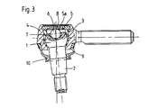
- the pin joint shown in FIG. 2 essentially consists of a ball pin 1 with a pin shaft 2 formed thereon, the ball pin 1 being mounted in a bearing shell 3, which is arranged in a housing 4, so as to be rotatable and pivotable.
- FIG. 1 shows the internal structure of a pivot joint according to the invention.
- the bearing shell 3 designed as a bushing is inserted into the housing 4 from above through an assembly opening 4a.
- the ball pin 1 with the molded-on shaft 2 is likewise inserted into the housing 4 from above, the shaft 2 protruding from the housing 4 through an opening 4b.
- the ball pin 1 is pressed into the housing 4 or the bearing shell 3 until the bearing shell 3 formed from an elastic material encloses a spherical ring-shaped bearing surface 1 a of the gel pin.
- the pivot joint designed according to the invention has a reset arrangement which acts largely independently of tolerance and wear.
- This reset arrangement is composed of a spring 5 and a ball 6, which in one on the stem 2 opposite end face 1b of the ball pin 1 formed counterbore 7 is mounted.
- the spring 5 resting on the ball 6 is supported on the back on a cover 8 which closes the assembly opening 4a of the housing 4 of the fully assembled pin joint.
- the cover 8 is inserted into the housing 4 and the edge of the assembly opening 4a is flanged over the cover 8.
- the spring 5 designed as a plate spring is supported with its edge in a recess 8a of the cover 8 and lies with its convex side against the ball 6 in such a way that the ball 6, which rests on conical surfaces 7a of the countersink 7, partially in a central bore 5a the spring 5 protrudes.
- the pivot joint When the pivot joint is deflected from its initial position, the ball 6 moves in a descriptive manner from the central bore 5a of the spring 5, whereby the spring 5 is compressed and tensioned in the axial direction. As a result of this deformation, the spring 5 tends to return to its original shape.
- the spring force of the spring 5 thus brings the ball 6 and thus also the ball pin 1 back into the starting position.
- journal shaft 2 is sealed off from the housing 4 by a sealing bellows 9, which is fixed on the journal shaft 2 with a clamping ring 10.
- the sealing bellows 9 is intended to prevent dirt and moisture from penetrating into the pivot joint.
Landscapes
- Engineering & Computer Science (AREA)
- General Engineering & Computer Science (AREA)
- Mechanical Engineering (AREA)
- Pivots And Pivotal Connections (AREA)
Claims (3)
- Articulation à pivot comprenant un boîtier (4) qui est fermé par un couvercle (8) et dans lequel un tourillon à rotule (1) est logé avec une possibilité de rotation sans jeu, par l'intermédiaire d'une surface portante en forme d'anneau sphérique (la), au moyen d'une coquille insérée formant coussinet (3) et avec une possibilité de pivotement à l'encontre d'une force de rappel à l'intérieur d'une zone délimitée, le tourillon à rotule (1) étant pourvu d'une fraisure conique (7) située à l'opposé du fût de tourillon (2) et destinée à une rotule (6) qui, pour produire la force de rappel, est sollicitée par un ressort (5) prenant appui sur le couvercle (8), caractérisée en ce que le ressort (5) est conçu sous la forme d'un ressort diaphragme dont la face convexe est appliquée contre la rotule (6) et dont le bord prend appui sur le couvercle (8).
- Articulation à pivot selon la revendication 1, caractérisée en ce que le bord du ressort (5) conçu sous la forme d'un ressort diaphragme prend appui dans un renfoncement (8a) du couvercle (8).
- Articulation à pivot selon la revendication 1 ou 2, caractérisée en ce que la coquille formant coussinet (3) est réalisée d'un seul tenant en polyamide.
Applications Claiming Priority (2)
| Application Number | Priority Date | Filing Date | Title |
|---|---|---|---|
| DE4305341A DE4305341C2 (de) | 1993-02-20 | 1993-02-20 | Zapfengelenk |
| DE4305341 | 1993-02-20 |
Publications (2)
| Publication Number | Publication Date |
|---|---|
| EP0612925A1 EP0612925A1 (fr) | 1994-08-31 |
| EP0612925B1 true EP0612925B1 (fr) | 1997-07-16 |
Family
ID=6481003
Family Applications (1)
| Application Number | Title | Priority Date | Filing Date |
|---|---|---|---|
| EP94101024A Expired - Lifetime EP0612925B1 (fr) | 1993-02-20 | 1994-01-25 | Articulation à pivot |
Country Status (8)
| Country | Link |
|---|---|
| US (1) | US5464296A (fr) |
| EP (1) | EP0612925B1 (fr) |
| JP (1) | JPH06280853A (fr) |
| BR (1) | BR9400596A (fr) |
| CZ (1) | CZ284078B6 (fr) |
| DE (2) | DE4305341C2 (fr) |
| ES (1) | ES2105361T3 (fr) |
| MX (1) | MX9401248A (fr) |
Families Citing this family (8)
| Publication number | Priority date | Publication date | Assignee | Title |
|---|---|---|---|---|
| US6010271A (en) * | 1996-02-01 | 2000-01-04 | Trw Inc. | Joint assembly |
| BR0006443A (pt) * | 2000-12-12 | 2004-06-08 | Dana Industrial Ltda | Articulação esférica com sistema de restrição de movimento angular |
| DE102011075324A1 (de) * | 2011-05-05 | 2012-11-08 | Zf Friedrichshafen Ag | Kugelgelenk für ein Fahrzeug |
| US9765811B2 (en) * | 2014-12-23 | 2017-09-19 | Federal-Mogul Motorparts Corporation | Ball socket assembly |
| US20170184149A1 (en) * | 2015-12-29 | 2017-06-29 | Leo D. Bernstein & Sons, Inc. | Auto-locking ball joint |
| US10605309B2 (en) * | 2017-02-15 | 2020-03-31 | Mevotech Lp | Snap-in bearing for automotive ball joint |
| RU2730763C1 (ru) | 2017-08-16 | 2020-08-26 | Малтиматик Инк. | Шаровой шарнир с вкладышем, полученным методом инжекционного формования |
| US12038039B2 (en) * | 2018-08-02 | 2024-07-16 | Federal-Mogul Motorparts Llc | Socket assembly with a coated washer |
Family Cites Families (12)
| Publication number | Priority date | Publication date | Assignee | Title |
|---|---|---|---|---|
| US2274420A (en) * | 1941-02-12 | 1942-02-24 | Katcher Morris | Knuckle joint |
| US2755116A (en) * | 1952-11-19 | 1956-07-17 | Thompson Prod Inc | Joint |
| GB796706A (en) * | 1956-01-06 | 1958-06-18 | Eng Productions Clevedon Ltd | Improvements in or relating to ball joints |
| DE1098382B (de) * | 1957-11-27 | 1961-01-26 | Lemfoerder Metallwarengesellsc | Abdichtung fuer Kugelgelenke, insbesondere wartungsfreie Gelenke fuer Lenkgestaenge von Kraftfahrzeugen |
| US3090642A (en) * | 1958-09-28 | 1963-05-21 | Viktor Langen | Ball and socket joints |
| DE1260236B (de) * | 1962-05-29 | 1968-02-01 | Gerd W Seifert Dipl Ing Dr Ing | Gelenklager |
| US3343856A (en) * | 1964-12-17 | 1967-09-26 | Ford Motor Co | Ball joint construction for motor vehicle suspension and steering systems |
| GB1125420A (en) * | 1967-01-20 | 1968-08-28 | Trw Inc | Improvements in or relating to ball joint assemblies |
| GB1372974A (en) * | 1972-02-11 | 1974-11-06 | Moog Industries Inc | Movable joint assembly with tolerance control |
| US4576499A (en) * | 1981-04-06 | 1986-03-18 | O & S Manufacturing Company | Ball and socket joints with wear indicator |
| JPH0523852Y2 (fr) * | 1988-10-18 | 1993-06-17 | ||
| JPH0623567B2 (ja) * | 1990-01-16 | 1994-03-30 | 株式会社ソミック石川 | ボールジョイント |
-
1993
- 1993-02-20 DE DE4305341A patent/DE4305341C2/de not_active Expired - Fee Related
-
1994
- 1994-01-25 ES ES94101024T patent/ES2105361T3/es not_active Expired - Lifetime
- 1994-01-25 EP EP94101024A patent/EP0612925B1/fr not_active Expired - Lifetime
- 1994-01-25 DE DE59403336T patent/DE59403336D1/de not_active Expired - Fee Related
- 1994-02-17 MX MX9401248A patent/MX9401248A/es unknown
- 1994-02-17 US US08/197,923 patent/US5464296A/en not_active Expired - Lifetime
- 1994-02-17 BR BR9400596A patent/BR9400596A/pt not_active IP Right Cessation
- 1994-02-18 JP JP6021374A patent/JPH06280853A/ja active Pending
- 1994-02-18 CZ CZ94360A patent/CZ284078B6/cs unknown
Also Published As
| Publication number | Publication date |
|---|---|
| US5464296A (en) | 1995-11-07 |
| BR9400596A (pt) | 1994-08-23 |
| ES2105361T3 (es) | 1997-10-16 |
| EP0612925A1 (fr) | 1994-08-31 |
| DE4305341A1 (de) | 1994-08-25 |
| CZ284078B6 (cs) | 1998-08-12 |
| DE59403336D1 (de) | 1997-08-21 |
| DE4305341C2 (de) | 1995-04-27 |
| MX9401248A (es) | 1994-08-31 |
| JPH06280853A (ja) | 1994-10-07 |
| CZ36094A3 (en) | 1994-09-14 |
Similar Documents
| Publication | Publication Date | Title |
|---|---|---|
| EP0481212B1 (fr) | Articulation à rotule | |
| EP1477690B1 (fr) | Articulation à rotule | |
| DE4338916C1 (de) | Kugelgelenk | |
| DE60304908T2 (de) | Spielfreie Befestigung eines Stellhebels am Schaft einer verstellbaren Leitschaufel einer Turbomaschine | |
| EP0922868B1 (fr) | Articulation à rotule | |
| EP1988269B1 (fr) | Clapet d'étranglement et installation d'échappement équipée de celui-ci | |
| EP0362566A2 (fr) | Support élastique | |
| DE4304775C2 (de) | Gelenklager | |
| DE10125143C2 (de) | Kugelgelenk | |
| DE3702277A1 (de) | Kugelgelenk | |
| DE2927423A1 (de) | Zweikreisdruckregler | |
| DE4305341C2 (de) | Zapfengelenk | |
| DE202004012604U1 (de) | Kugelgelenk | |
| EP1196936B1 (fr) | Contact mobile a faible resistance electrique | |
| DE60219018T2 (de) | Gelenkverbindung | |
| DE112019003614T5 (de) | Faserverstärktes lager für eine kugelpfannenbaugruppe, kugelpfannenbaugruppe damit und verfahren zu deren herstellung | |
| DE9205662U1 (de) | Rollenanordnung für Raupenkette | |
| DE10157934A1 (de) | Buchse zur Einschränkung einer Bewegung eines Kugelgelenks | |
| DE1797555U (de) | Gelenk. | |
| EP1432919B1 (fr) | Joint a rotule | |
| DE102007051721A1 (de) | Kugelgelenk | |
| DE10354727B4 (de) | Lagerbuchse | |
| DE2755999C2 (de) | Tandem-Drehwiderstand | |
| DE3207013C2 (de) | Kugelgelenk | |
| DE4320831C1 (de) | Ankerlagerung für ein Klappankerrelais |
Legal Events
| Date | Code | Title | Description |
|---|---|---|---|
| PUAI | Public reference made under article 153(3) epc to a published international application that has entered the european phase |
Free format text: ORIGINAL CODE: 0009012 |
|
| AK | Designated contracting states |
Kind code of ref document: A1 Designated state(s): DE ES FR GB IT SE |
|
| 17P | Request for examination filed |
Effective date: 19941019 |
|
| 17Q | First examination report despatched |
Effective date: 19951026 |
|
| GRAG | Despatch of communication of intention to grant |
Free format text: ORIGINAL CODE: EPIDOS AGRA |
|
| GRAH | Despatch of communication of intention to grant a patent |
Free format text: ORIGINAL CODE: EPIDOS IGRA |
|
| GRAH | Despatch of communication of intention to grant a patent |
Free format text: ORIGINAL CODE: EPIDOS IGRA |
|
| GRAA | (expected) grant |
Free format text: ORIGINAL CODE: 0009210 |
|
| AK | Designated contracting states |
Kind code of ref document: B1 Designated state(s): DE ES FR GB IT SE |
|
| PG25 | Lapsed in a contracting state [announced via postgrant information from national office to epo] |
Ref country code: FR Free format text: THE PATENT HAS BEEN ANNULLED BY A DECISION OF A NATIONAL AUTHORITY Effective date: 19970716 |
|
| GBT | Gb: translation of ep patent filed (gb section 77(6)(a)/1977) |
Effective date: 19970716 |
|
| REF | Corresponds to: |
Ref document number: 59403336 Country of ref document: DE Date of ref document: 19970821 |
|
| ITF | It: translation for a ep patent filed | ||
| ET | Fr: translation filed | ||
| REG | Reference to a national code |
Ref country code: ES Ref legal event code: FG2A Ref document number: 2105361 Country of ref document: ES Kind code of ref document: T3 |
|
| PG25 | Lapsed in a contracting state [announced via postgrant information from national office to epo] |
Ref country code: GB Free format text: LAPSE BECAUSE OF NON-PAYMENT OF DUE FEES Effective date: 19980125 |
|
| PG25 | Lapsed in a contracting state [announced via postgrant information from national office to epo] |
Ref country code: SE Free format text: LAPSE BECAUSE OF NON-PAYMENT OF DUE FEES Effective date: 19980126 Ref country code: ES Free format text: LAPSE BECAUSE OF NON-PAYMENT OF DUE FEES Effective date: 19980126 |
|
| PLBE | No opposition filed within time limit |
Free format text: ORIGINAL CODE: 0009261 |
|
| STAA | Information on the status of an ep patent application or granted ep patent |
Free format text: STATUS: NO OPPOSITION FILED WITHIN TIME LIMIT |
|
| 26N | No opposition filed | ||
| GBPC | Gb: european patent ceased through non-payment of renewal fee |
Effective date: 19980125 |
|
| EUG | Se: european patent has lapsed |
Ref document number: 94101024.1 |
|
| REG | Reference to a national code |
Ref country code: FR Ref legal event code: ST |
|
| PGFP | Annual fee paid to national office [announced via postgrant information from national office to epo] |
Ref country code: DE Payment date: 20040130 Year of fee payment: 11 |
|
| REG | Reference to a national code |
Ref country code: ES Ref legal event code: FD2A Effective date: 19990211 |
|
| PG25 | Lapsed in a contracting state [announced via postgrant information from national office to epo] |
Ref country code: IT Free format text: LAPSE BECAUSE OF NON-PAYMENT OF DUE FEES;WARNING: LAPSES OF ITALIAN PATENTS WITH EFFECTIVE DATE BEFORE 2007 MAY HAVE OCCURRED AT ANY TIME BEFORE 2007. THE CORRECT EFFECTIVE DATE MAY BE DIFFERENT FROM THE ONE RECORDED. Effective date: 20050125 |
|
| PG25 | Lapsed in a contracting state [announced via postgrant information from national office to epo] |
Ref country code: DE Free format text: LAPSE BECAUSE OF NON-PAYMENT OF DUE FEES Effective date: 20050802 |