EP0612944B1 - Elément de fixation monobloc - Google Patents
Elément de fixation monobloc Download PDFInfo
- Publication number
- EP0612944B1 EP0612944B1 EP93120753A EP93120753A EP0612944B1 EP 0612944 B1 EP0612944 B1 EP 0612944B1 EP 93120753 A EP93120753 A EP 93120753A EP 93120753 A EP93120753 A EP 93120753A EP 0612944 B1 EP0612944 B1 EP 0612944B1
- Authority
- EP
- European Patent Office
- Prior art keywords
- holding
- supporting region
- holding element
- element according
- region
- Prior art date
- Legal status (The legal status is an assumption and is not a legal conclusion. Google has not performed a legal analysis and makes no representation as to the accuracy of the status listed.)
- Expired - Lifetime
Links
- 238000010276 construction Methods 0.000 description 8
- 238000007789 sealing Methods 0.000 description 4
- 238000000926 separation method Methods 0.000 description 4
- 230000005540 biological transmission Effects 0.000 description 2
- 230000002411 adverse Effects 0.000 description 1
- 230000000694 effects Effects 0.000 description 1
- 238000003780 insertion Methods 0.000 description 1
- 230000037431 insertion Effects 0.000 description 1
- 238000004519 manufacturing process Methods 0.000 description 1
- 239000000463 material Substances 0.000 description 1
- 239000000725 suspension Substances 0.000 description 1
Images
Classifications
-
- F—MECHANICAL ENGINEERING; LIGHTING; HEATING; WEAPONS; BLASTING
- F16—ENGINEERING ELEMENTS AND UNITS; GENERAL MEASURES FOR PRODUCING AND MAINTAINING EFFECTIVE FUNCTIONING OF MACHINES OR INSTALLATIONS; THERMAL INSULATION IN GENERAL
- F16C—SHAFTS; FLEXIBLE SHAFTS; ELEMENTS OR CRANKSHAFT MECHANISMS; ROTARY BODIES OTHER THAN GEARING ELEMENTS; BEARINGS
- F16C35/00—Rigid support of bearing units; Housings, e.g. caps, covers
-
- F—MECHANICAL ENGINEERING; LIGHTING; HEATING; WEAPONS; BLASTING
- F16—ENGINEERING ELEMENTS AND UNITS; GENERAL MEASURES FOR PRODUCING AND MAINTAINING EFFECTIVE FUNCTIONING OF MACHINES OR INSTALLATIONS; THERMAL INSULATION IN GENERAL
- F16L—PIPES; JOINTS OR FITTINGS FOR PIPES; SUPPORTS FOR PIPES, CABLES OR PROTECTIVE TUBING; MEANS FOR THERMAL INSULATION IN GENERAL
- F16L55/00—Devices or appurtenances for use in, or in connection with, pipes or pipe systems
- F16L55/02—Energy absorbers; Noise absorbers
- F16L55/033—Noise absorbers
- F16L55/035—Noise absorbers in the form of specially adapted hangers or supports
-
- F—MECHANICAL ENGINEERING; LIGHTING; HEATING; WEAPONS; BLASTING
- F16—ENGINEERING ELEMENTS AND UNITS; GENERAL MEASURES FOR PRODUCING AND MAINTAINING EFFECTIVE FUNCTIONING OF MACHINES OR INSTALLATIONS; THERMAL INSULATION IN GENERAL
- F16L—PIPES; JOINTS OR FITTINGS FOR PIPES; SUPPORTS FOR PIPES, CABLES OR PROTECTIVE TUBING; MEANS FOR THERMAL INSULATION IN GENERAL
- F16L3/00—Supports for pipes, cables or protective tubing, e.g. hangers, holders, clamps, cleats, clips, brackets
- F16L3/22—Supports for pipes, cables or protective tubing, e.g. hangers, holders, clamps, cleats, clips, brackets specially adapted for supporting a number of parallel pipes at intervals
- F16L3/237—Supports for pipes, cables or protective tubing, e.g. hangers, holders, clamps, cleats, clips, brackets specially adapted for supporting a number of parallel pipes at intervals for two pipes
-
- H—ELECTRICITY
- H02—GENERATION; CONVERSION OR DISTRIBUTION OF ELECTRIC POWER
- H02G—INSTALLATION OF ELECTRIC CABLES OR LINES, OR OF COMBINED OPTICAL AND ELECTRIC CABLES OR LINES
- H02G3/00—Installations of electric cables or lines or protective tubing therefor in or on buildings, equivalent structures or vehicles
- H02G3/26—Installations of cables, lines, or separate protective tubing therefor directly on or in walls, ceilings, or floors
Definitions
- the invention relates to a one-piece holding element made of plastic, in particular for at least one pipeline, with at least one storage area and at least one holding area for partially encompassing the circumference of the pipeline, the storage area being arranged between two holding areas via resilient webs and the two holding areas being connected to form a base body are.
- Such a holding element is already known as prior art (DE-PS 30 02 031), which is used in particular for holding gasoline lines in a motor vehicle.
- the holding area consists of two shell-shaped holders in the form of an inner shell, which partially encompasses the circumference of the pipeline, and an outer shell surrounding the inner shell at a distance.
- the storage area is located between two holding areas and has a continuous opening which is fastened to a profile bolt arranged on a motor vehicle via an insertion end.
- GB-2 098 699 A, GB-PS 1 379 543, DE-OS 28 16 181 have a similar structure; there is in each case a direct connection between the storage area and an individual or a plurality of holding areas for holding tubular elements.
- the present invention has for its object to provide a one-piece holding element of the type mentioned, which avoids the aforementioned disadvantages with a simple structure and reduces vibrations and largely reduces noise transmission.
- the holding areas are connected via resilient webs to a body containing the bearing area, which has an adverse effect on the robustness or durability of the construction against continuous loads and is not noise-reducing.
- the holding areas form a body which is connected by meandering, long webs to the bearing area located therefrom in order to achieve a soft suspension.
- this construction disadvantageously requires a space-consuming, high design. Both constructions differ significantly from the invention.
- the bearing area can be arranged between two holding areas, the two holding areas being connected to form a base body and the base body being connected to the cylindrical bearing area via a plurality of resilient webs.
- three resilient webs distributed over the circumference can connect the base body to the storage area.
- the webs can extend diagonally through an intermediate space between the base body and the storage areas.
- the webs can extend from the open end of the storage area through the intermediate space to the diagonally opposite side of the base body.
- each holding area consists of two shell-shaped holders with an inner shell partially encompassing the circumference of the pipeline and an outer shell surrounding the inner shell at a distance each holding area has a recess delimited by a wall on the inside, the two walls being connected to one another via connecting areas and enclosing an intermediate space in the interior of which the storage area is arranged.
- This bearing area can have longitudinal ribs distributed on the inside over the circumference.
- the webs do not run in a straight line, but rather, for example, have a wave shape, so that this advantageously brings about a further reduction in undesired vibrations and noise transmission.
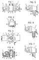
- a one-piece, made of plastic holding element 1 is shown.
- This essentially consists of a storage area 2, which is arranged between two holding areas 3 and 4.
- Each of these holding areas 3 and 4 serves z. B. to hold a pipe, not shown:
- Each holding area 3, 4 consists of two shell-shaped holders with an inner shell 20 or 20 'partially encompassing the circumference of the pipeline and an outer shell 21 or 21' surrounding the inner shell at a distance.
- the two holding areas 3 and 4 are connected to a base body 10 according to FIG. 3 via two connecting areas 27 and 28.
- This storage area 2 is e.g. cylindrical and connected to the base body 10 via three resilient webs 5, 5 ', 5' 'distributed over the circumference.
- the webs 5, 5 ′ and 5 ′′ extend from the open end 12 of this storage area 2 through the intermediate space 8 to the diagonally opposite side of the base body 10. This creates a long way, so that undesirable vibrations avoided and noise reduction is achieved.
- each holding area 3, 4 has a recess 23 or 23 'delimited on the inside by a wall 25 or 25'. These walls merge into the connecting areas 27 and 28 and form part of the base body 10.
- the bearing area 2 has longitudinal ribs 30 distributed on the inside over the circumference of the opening 15. These longitudinal ribs 30 can be incorporated in a profiled bolt (not shown in any more detail), which in turn is fastened, for example, to the body of a motor vehicle.
- the bearing area 2 is designed as an opening 15 with longitudinal ribs 30, FIGS. 5 to 7 show further design options: according to FIG. 5, the bearing area 2 can be made from one foot 31 with two opposing elastic wings 32 and 33, above which an elastic, circumferential sealing lip 30 is arranged.
- the sealing lip 30 can also be omitted.
- a specially designed holding part 37 is used, in which ribs arranged one behind the other are provided; these can be stored in a profiled bolt, not shown, attached to a carrier.
Landscapes
- Engineering & Computer Science (AREA)
- General Engineering & Computer Science (AREA)
- Mechanical Engineering (AREA)
- Architecture (AREA)
- Civil Engineering (AREA)
- Structural Engineering (AREA)
- Supports For Pipes And Cables (AREA)
- Clamps And Clips (AREA)
- Vibration Prevention Devices (AREA)
Claims (7)
- Elément monobloc de retenue (1) en matière plastique, en particulier pour au moins un conduit tubulaire, comprenant au moins une zone de portée (2) et au moins une zone de retenue (3, 4) pour emprisonner partiellement le pourtour du conduit tubulaire, la zone de portée (2) étant disposée entre deux zones de retenue, par l'intermédiaire de membrures élastiques, et les deux zones de retenue (3, 4) étant reliées en un corps de base (10),
caractérisé par le fait
que le corps de base (10) ceinture un espace intercalaire (8), à l'intérieur duquel la zone de portée (2) est ménagée et est reliée audit corps de base (10) par l'intermédiaire d'au moins une membrure élastique (5, 5', 5''). - Elément de retenue selon la revendication 1,
caractérisé par le fait
que la zone de portée (2) est de réalisation cylindrique. - Elément de retenue selon l'une des revendications 1 ou 2,
caractérisé par le fait
que trois membrures élastiques (5, 5', 5''), réparties sur le pourtour, relient le corps de base (10) à la zone de portée (2). - Elément de retenue selon l'une des revendications précédentes,
caractérisé par le fait
que les membrures (5, 5', 5'') s'étendent diagonalement à travers l'espace intercalaire (8) situé entre le corps de base (10) et la zone de portée (2). - Elément de retenue selon la revendication 4, présentant une zone de portée ouverte d'un côté,
caractérisé par le fait
que les membrures (5, 5', 5'') traversent l'espace intercalaire (8) à partir d'une extrémité (12) de la zone de portée (2), vers le côté diagonalement opposé du corps de base (10). - Elément de retenue selon l'une des revendications précédentes,
dans lequel chaque zone de retenue se compose de deux supports en forme de coquilles, avec une coquille intérieure emprisonnant partiellement le pourtour du conduit tubulaire, et une coquille extérieure entourant à distance la coquille intérieure,
caractérisé par le faitque chaque zone de retenue (3, 4) présente, intérieurement, une échancrure (23, 23') délimitée par une paroi (25, 25') ; etque les deux parois (25, 25') sont reliées l'une à l'autre par l'intermédiaire de zones de solidarisation (27, 28), et ceinturent l'espace intercalaire (8) à l'intérieur duquel la zone de portée (2) est disposée. - Elément de retenue selon l'une des revendications précédentes,
caractérisé par le fait
que la zone de portée (2) présente des nervures longitudinales réparties intérieurement sur le pourtour, est constituée d'un tenon profilé (35) ou comporte des ailettes élastiques (32, 33).
Applications Claiming Priority (2)
| Application Number | Priority Date | Filing Date | Title |
|---|---|---|---|
| DE4302408A DE4302408A1 (de) | 1993-01-28 | 1993-01-28 | Einteiliges Halteelement |
| DE4302408 | 1993-01-28 |
Publications (2)
| Publication Number | Publication Date |
|---|---|
| EP0612944A1 EP0612944A1 (fr) | 1994-08-31 |
| EP0612944B1 true EP0612944B1 (fr) | 1996-11-13 |
Family
ID=6479149
Family Applications (1)
| Application Number | Title | Priority Date | Filing Date |
|---|---|---|---|
| EP93120753A Expired - Lifetime EP0612944B1 (fr) | 1993-01-28 | 1993-12-22 | Elément de fixation monobloc |
Country Status (6)
| Country | Link |
|---|---|
| US (1) | US5458303A (fr) |
| EP (1) | EP0612944B1 (fr) |
| JP (1) | JPH0791570A (fr) |
| KR (1) | KR100298551B1 (fr) |
| DE (2) | DE4302408A1 (fr) |
| ES (1) | ES2095553T3 (fr) |
Families Citing this family (33)
| Publication number | Priority date | Publication date | Assignee | Title |
|---|---|---|---|---|
| IT1278968B1 (it) * | 1995-03-03 | 1997-12-02 | Lys Fusion Spa | Graffa per il fissaggio di tubi conduttori e simili organi |
| DE19529897A1 (de) * | 1995-08-14 | 1997-02-20 | United Carr Gmbh Trw | Halteelement aus Kunststoff |
| DE19540168C2 (de) * | 1995-10-27 | 1997-09-18 | Emhart Inc | Halteelement zum Befestigen mindestens eines rohrförmigen Bauteils an einem Träger |
| USD398313S (en) | 1997-02-21 | 1998-09-15 | Abb Power T&D Company, Inc. | Bushing clamp and parking stand |
| US5941483A (en) * | 1998-04-24 | 1999-08-24 | Volvo Trucks North America, Inc. | Service line clamp with cable tie mount |
| US6601802B1 (en) | 1999-12-30 | 2003-08-05 | Lsp Products Group Inc | Method for making extruded acoustic pipe support |
| US6915990B2 (en) * | 2001-05-29 | 2005-07-12 | Newfrey Llc | Pipe holding fastener |
| JP2002349762A (ja) | 2001-05-29 | 2002-12-04 | Nippon Pop Rivets & Fasteners Ltd | 管等の保持具 |
| JP2002349763A (ja) * | 2001-05-30 | 2002-12-04 | Nippon Pop Rivets & Fasteners Ltd | 管等の保持具 |
| US6564423B2 (en) | 2001-06-21 | 2003-05-20 | Black & Decker Inc. | Two piece upright handle assembly for a vacuum cleaner system |
| US6604725B1 (en) | 2002-01-24 | 2003-08-12 | Robert Bosch Corporation | Device for securing a hydraulic modulator to a vehicle |
| DE10304033A1 (de) * | 2003-02-01 | 2004-08-05 | Adam Opel Ag | Befestigungselement für Rohrleitungen in Kraftfahrzeugen |
| DE10306905C5 (de) * | 2003-02-18 | 2012-05-24 | Itw Automotive Products Gmbh & Co. Kg | Halteelement |
| DE10306904C5 (de) * | 2003-02-18 | 2012-05-03 | Itw Automotive Products Gmbh & Co. Kg | Halteelement |
| US6926237B2 (en) | 2003-05-29 | 2005-08-09 | Illinois Tool Works Inc. | Vibration damping clip |
| JP2005188578A (ja) * | 2003-12-25 | 2005-07-14 | Nippon Pop Rivets & Fasteners Ltd | パイプ等の長尺物のクランプ |
| JP4597535B2 (ja) * | 2004-01-22 | 2010-12-15 | 株式会社 日立ディスプレイズ | 液晶表示装置 |
| ITTO20040088A1 (it) * | 2004-02-17 | 2004-05-17 | Itw Automotive Italia S R L | Elemento di ritegno a fascetta per componenti assialsimmetrici quali cavi o tubetti, in particolare per l'applicazione su veicoli |
| US7090169B2 (en) * | 2004-05-20 | 2006-08-15 | Curt Swanson | Retaining clamp for alignment of risers when packing a parachute |
| DE102005032535B4 (de) * | 2005-07-12 | 2008-03-27 | A. Raymond & Cie | Vorrichtung zum Befestigen wenigstens eines Gegenstandes an einem mit einem Befestigungsbolzen versehenen Trägerteil |
| US7594583B2 (en) * | 2006-02-23 | 2009-09-29 | Gm Global Technology Operations, Inc. | Retaining support member for fuel filler pipe |
| US7770851B2 (en) * | 2006-12-21 | 2010-08-10 | Thomas & Betts International, Inc. | Retaining element including enhanced engagement features |
| US7740209B2 (en) * | 2007-07-27 | 2010-06-22 | Hewlett-Packard Development Company, L.P. | Cable routing device |
| US8162156B1 (en) | 2009-06-29 | 2012-04-24 | Bruce Crisman | Implement holder and methods of use |
| USD631152S1 (en) * | 2009-12-10 | 2011-01-18 | Medline Industries Inc. | IV pole accessory |
| USD634004S1 (en) * | 2009-12-10 | 2011-03-08 | Medline Industries Inc. | IV pole accessory |
| JP5824031B2 (ja) * | 2010-04-02 | 2015-11-25 | イリノイ トゥール ワークス インコーポレイティド | 防振用の車両取り付けアセンブリ |
| DE102011114543B4 (de) * | 2011-09-30 | 2013-09-12 | Faurecia Autositze Gmbh | Kraftfahrzeugsitz |
| GB201117028D0 (en) * | 2011-10-04 | 2011-11-16 | Rolls Royce Plc | Gas turbine engine mounting arrangements |
| DE102015112207A1 (de) | 2015-07-27 | 2017-02-02 | Newfrey Llc | Clip zum Festlegen eines länglichen Gegenstandes |
| DE102016222708B4 (de) * | 2016-11-18 | 2024-06-06 | Bayerische Motoren Werke Aktiengesellschaft | Aufnahmevorrichtung zur Aufnahme eines leitungsförmigen Bauteils |
| KR102557404B1 (ko) * | 2017-05-31 | 2023-07-19 | 삼성전자주식회사 | 세탁기 |
| US12509932B1 (en) * | 2024-06-28 | 2025-12-30 | Nissan North America, Inc. | Clip assembly for vehicle torsion rods |
Family Cites Families (10)
| Publication number | Priority date | Publication date | Assignee | Title |
|---|---|---|---|---|
| US4591119A (en) * | 1984-03-23 | 1986-05-27 | Trw United-Carr Gmbh | Pipe support |
| DE3440995A1 (de) * | 1984-11-09 | 1986-05-15 | Fa. A. Raymond, 7850 Lörrach | Befestigungselement fuer rohrleitungen |
| JPS6189506U (fr) * | 1984-11-19 | 1986-06-11 | ||
| DE3802698C3 (de) * | 1988-01-29 | 1996-09-26 | United Carr Gmbh Trw | Leitungshalter aus Kunststoff |
| DE3902499A1 (de) * | 1989-01-27 | 1990-08-02 | United Carr Gmbh Trw | Halteelement aus kunststoff |
| DE9011879U1 (de) * | 1990-08-16 | 1990-10-18 | A. Raymond KG, 7850 Lörrach | Schwingungsdämpfendes Befestigungselement für Rohrleitungen |
| DE4034546C2 (de) * | 1990-10-30 | 1993-09-30 | United Carr Gmbh Trw | Halteelement aus Kunststoff |
| DE4039822C1 (fr) * | 1990-12-13 | 1992-07-23 | A. Raymond Kg, 7850 Loerrach, De | |
| JP2556979Y2 (ja) * | 1991-03-01 | 1997-12-08 | 株式会社ニフコ | 線、棒状物のクランプ |
| US5316245A (en) * | 1991-10-25 | 1994-05-31 | Trw United Carr Gmbh & Co., Kg | Plastic holding element |
-
1993
- 1993-01-28 DE DE4302408A patent/DE4302408A1/de not_active Withdrawn
- 1993-12-22 EP EP93120753A patent/EP0612944B1/fr not_active Expired - Lifetime
- 1993-12-22 DE DE59304485T patent/DE59304485D1/de not_active Expired - Fee Related
- 1993-12-22 ES ES93120753T patent/ES2095553T3/es not_active Expired - Lifetime
-
1994
- 1994-01-18 US US08/182,659 patent/US5458303A/en not_active Expired - Lifetime
- 1994-01-26 KR KR1019940001337A patent/KR100298551B1/ko not_active Expired - Fee Related
- 1994-01-28 JP JP6008185A patent/JPH0791570A/ja active Pending
Also Published As
| Publication number | Publication date |
|---|---|
| KR940018573A (ko) | 1994-08-18 |
| EP0612944A1 (fr) | 1994-08-31 |
| US5458303A (en) | 1995-10-17 |
| ES2095553T3 (es) | 1997-02-16 |
| DE4302408A1 (de) | 1994-08-04 |
| KR100298551B1 (ko) | 2001-11-22 |
| JPH0791570A (ja) | 1995-04-04 |
| DE59304485D1 (de) | 1996-12-19 |
Similar Documents
| Publication | Publication Date | Title |
|---|---|---|
| EP0612944B1 (fr) | Elément de fixation monobloc | |
| EP0758728B1 (fr) | Elément de maintien en plastique | |
| EP0726401B1 (fr) | Liaison entre un support et un panneau | |
| EP0761986B1 (fr) | Elément de connexion en plastique | |
| DE3713503C1 (de) | Verschlussdeckel aus Kunststoff | |
| EP0421056B1 (fr) | Dispositif de fixation en matière plastique | |
| EP0483636B1 (fr) | Elément de retenue en matière plastique | |
| EP0379722A1 (fr) | Elément de retenue consistant en matières plastiques | |
| EP0621169A1 (fr) | Bouchon en plastique | |
| DE2952176A1 (de) | Fuehrungslenker fuer radaufhaengungen von kraftfahrzeugen | |
| WO1999020907A1 (fr) | Assemblage entre un support, notamment un element de carrosserie d'un vehicule a moteur, et un panneau | |
| DE2937083C2 (de) | Radblende, insbesondere für die Räder von Personenkraftwagen | |
| EP0155485B1 (fr) | Articulation à rotule axiale pour tige de guidage dans véhicules automobiles | |
| DE3610829A1 (de) | Elastisches lagerteil als einsatz in ein halteelement zur halterung mindestens einer leitung | |
| DE3048793C2 (de) | Tragkörper für Radführungsglieder von Kraftfahrzeugrädern, insbesondere Hinterrädern | |
| DE2943139A1 (de) | Radblende, insbesondere fuer raeder von personenkraftwagen | |
| DE3739514A1 (de) | Dichtung | |
| DE2331324C3 (de) | Scheibenwischer für Fahrzeuge, insbesondere Kraftfahrzeuge | |
| DE3011345C2 (de) | Verbindung von Rohren mit Randbereichen von Blechen o.dgl. flächigen Bauteilen | |
| EP3568604B1 (fr) | Soufflet comportant au moins une rainure interne | |
| DE7415154U (de) | Lagerboeckchen mit lagerachse insbesondere zur aufnahme einer sonnenblende in fahrzeugen | |
| DE20102217U1 (de) | Filter für Flüssigkeiten, insbesondere Kraftstoffe | |
| DE9305934U1 (de) | Einteiliges Halteelement | |
| EP0672836A1 (fr) | Dispositif de fixation | |
| DE2810163A1 (de) | Wickeltraeger mit parallel zu seiner achse verlaufenden tragelementen |
Legal Events
| Date | Code | Title | Description |
|---|---|---|---|
| PUAI | Public reference made under article 153(3) epc to a published international application that has entered the european phase |
Free format text: ORIGINAL CODE: 0009012 |
|
| AK | Designated contracting states |
Kind code of ref document: A1 Designated state(s): DE ES FR GB NL SE |
|
| 17P | Request for examination filed |
Effective date: 19940802 |
|
| 17Q | First examination report despatched |
Effective date: 19941114 |
|
| GRAG | Despatch of communication of intention to grant |
Free format text: ORIGINAL CODE: EPIDOS AGRA |
|
| GRAH | Despatch of communication of intention to grant a patent |
Free format text: ORIGINAL CODE: EPIDOS IGRA |
|
| GRAH | Despatch of communication of intention to grant a patent |
Free format text: ORIGINAL CODE: EPIDOS IGRA |
|
| GRAA | (expected) grant |
Free format text: ORIGINAL CODE: 0009210 |
|
| AK | Designated contracting states |
Kind code of ref document: B1 Designated state(s): DE ES FR GB NL SE |
|
| PG25 | Lapsed in a contracting state [announced via postgrant information from national office to epo] |
Ref country code: NL Free format text: LAPSE BECAUSE OF FAILURE TO SUBMIT A TRANSLATION OF THE DESCRIPTION OR TO PAY THE FEE WITHIN THE PRESCRIBED TIME-LIMIT Effective date: 19961113 |
|
| REF | Corresponds to: |
Ref document number: 59304485 Country of ref document: DE Date of ref document: 19961219 |
|
| PG25 | Lapsed in a contracting state [announced via postgrant information from national office to epo] |
Ref country code: SE Effective date: 19970213 |
|
| ET | Fr: translation filed | ||
| REG | Reference to a national code |
Ref country code: ES Ref legal event code: FG2A Ref document number: 2095553 Country of ref document: ES Kind code of ref document: T3 |
|
| GBT | Gb: translation of ep patent filed (gb section 77(6)(a)/1977) |
Effective date: 19970123 |
|
| NLV1 | Nl: lapsed or annulled due to failure to fulfill the requirements of art. 29p and 29m of the patents act | ||
| PLBE | No opposition filed within time limit |
Free format text: ORIGINAL CODE: 0009261 |
|
| STAA | Information on the status of an ep patent application or granted ep patent |
Free format text: STATUS: NO OPPOSITION FILED WITHIN TIME LIMIT |
|
| 26N | No opposition filed | ||
| REG | Reference to a national code |
Ref country code: GB Ref legal event code: IF02 |
|
| PGFP | Annual fee paid to national office [announced via postgrant information from national office to epo] |
Ref country code: ES Payment date: 20071217 Year of fee payment: 15 |
|
| PGFP | Annual fee paid to national office [announced via postgrant information from national office to epo] |
Ref country code: GB Payment date: 20071106 Year of fee payment: 15 |
|
| PGFP | Annual fee paid to national office [announced via postgrant information from national office to epo] |
Ref country code: DE Payment date: 20071228 Year of fee payment: 15 |
|
| PGFP | Annual fee paid to national office [announced via postgrant information from national office to epo] |
Ref country code: FR Payment date: 20071204 Year of fee payment: 15 |
|
| GBPC | Gb: european patent ceased through non-payment of renewal fee |
Effective date: 20081222 |
|
| REG | Reference to a national code |
Ref country code: FR Ref legal event code: ST Effective date: 20090831 |
|
| PG25 | Lapsed in a contracting state [announced via postgrant information from national office to epo] |
Ref country code: DE Free format text: LAPSE BECAUSE OF NON-PAYMENT OF DUE FEES Effective date: 20090701 |
|
| PG25 | Lapsed in a contracting state [announced via postgrant information from national office to epo] |
Ref country code: GB Free format text: LAPSE BECAUSE OF NON-PAYMENT OF DUE FEES Effective date: 20081222 |
|
| REG | Reference to a national code |
Ref country code: ES Ref legal event code: FD2A Effective date: 20081223 |
|
| PG25 | Lapsed in a contracting state [announced via postgrant information from national office to epo] |
Ref country code: FR Free format text: LAPSE BECAUSE OF NON-PAYMENT OF DUE FEES Effective date: 20081231 Ref country code: ES Free format text: LAPSE BECAUSE OF NON-PAYMENT OF DUE FEES Effective date: 20081223 |