EP0612964A1 - Regelvorrichtung für die Klimatisierung - Google Patents
Regelvorrichtung für die Klimatisierung Download PDFInfo
- Publication number
- EP0612964A1 EP0612964A1 EP94400365A EP94400365A EP0612964A1 EP 0612964 A1 EP0612964 A1 EP 0612964A1 EP 94400365 A EP94400365 A EP 94400365A EP 94400365 A EP94400365 A EP 94400365A EP 0612964 A1 EP0612964 A1 EP 0612964A1
- Authority
- EP
- European Patent Office
- Prior art keywords
- signal
- temperature
- air
- room
- comparator
- Prior art date
- Legal status (The legal status is an assumption and is not a legal conclusion. Google has not performed a legal analysis and makes no representation as to the accuracy of the status listed.)
- Withdrawn
Links
Images



Classifications
-
- B—PERFORMING OPERATIONS; TRANSPORTING
- B60—VEHICLES IN GENERAL
- B60H—ARRANGEMENTS OF HEATING, COOLING, VENTILATING OR OTHER AIR-TREATING DEVICES SPECIALLY ADAPTED FOR PASSENGER OR GOODS SPACES OF VEHICLES
- B60H1/00—Heating, cooling or ventilating devices
- B60H1/00642—Control systems or circuits; Control members or indication devices for heating, cooling or ventilating devices
- B60H1/00971—Control systems or circuits characterised by including features for locking or memorising of control modes
-
- B—PERFORMING OPERATIONS; TRANSPORTING
- B61—RAILWAYS
- B61D—BODY DETAILS OR KINDS OF RAILWAY VEHICLES
- B61D27/00—Heating, cooling, ventilating, or air-conditioning
- B61D27/0018—Air-conditioning means, i.e. combining at least two of the following ways of treating or supplying air, namely heating, cooling or ventilating
-
- F—MECHANICAL ENGINEERING; LIGHTING; HEATING; WEAPONS; BLASTING
- F24—HEATING; RANGES; VENTILATING
- F24F—AIR-CONDITIONING; AIR-HUMIDIFICATION; VENTILATION; USE OF AIR CURRENTS FOR SCREENING
- F24F11/00—Control or safety arrangements
- F24F11/62—Control or safety arrangements characterised by the type of control or by internal processing, e.g. using fuzzy logic, adaptive control or estimation of values
- F24F11/63—Electronic processing
-
- F—MECHANICAL ENGINEERING; LIGHTING; HEATING; WEAPONS; BLASTING
- F24—HEATING; RANGES; VENTILATING
- F24F—AIR-CONDITIONING; AIR-HUMIDIFICATION; VENTILATION; USE OF AIR CURRENTS FOR SCREENING
- F24F11/00—Control or safety arrangements
- F24F11/88—Electrical aspects, e.g. circuits
-
- F—MECHANICAL ENGINEERING; LIGHTING; HEATING; WEAPONS; BLASTING
- F25—REFRIGERATION OR COOLING; COMBINED HEATING AND REFRIGERATION SYSTEMS; HEAT PUMP SYSTEMS; MANUFACTURE OR STORAGE OF ICE; LIQUEFACTION SOLIDIFICATION OF GASES
- F25B—REFRIGERATION MACHINES, PLANTS OR SYSTEMS; COMBINED HEATING AND REFRIGERATION SYSTEMS; HEAT PUMP SYSTEMS
- F25B29/00—Combined heating and refrigeration systems, e.g. operating alternately or simultaneously
-
- F—MECHANICAL ENGINEERING; LIGHTING; HEATING; WEAPONS; BLASTING
- F24—HEATING; RANGES; VENTILATING
- F24F—AIR-CONDITIONING; AIR-HUMIDIFICATION; VENTILATION; USE OF AIR CURRENTS FOR SCREENING
- F24F11/00—Control or safety arrangements
- F24F11/30—Control or safety arrangements for purposes related to the operation of the system, e.g. for safety or monitoring
-
- F—MECHANICAL ENGINEERING; LIGHTING; HEATING; WEAPONS; BLASTING
- F24—HEATING; RANGES; VENTILATING
- F24F—AIR-CONDITIONING; AIR-HUMIDIFICATION; VENTILATION; USE OF AIR CURRENTS FOR SCREENING
- F24F2110/00—Control inputs relating to air properties
- F24F2110/10—Temperature
Definitions
- the present invention relates to a device for regulating the air conditioning of a fixed or moving room, the room being air conditioned by means of a conditioning unit.
- the air conditioning regulation must ensure, inside a room, a temperature controlled by a set temperature.
- the regulation must also ensure the speed of the air conditioning start-up phases.
- the air conditioning regulation of rail cars must allow rapid commissioning and then ensure a constant temperature for passenger comfort.
- Air conditioning regulation is often performed by Proportional-Integral-Derivative (PID) systems which, in particular in the rail sector, are not entirely satisfactory.
- PID Proportional-Integral-Derivative
- Air conditioning regulation is often performed by Proportional-Integral-Derivative (PID) systems which, in particular in the rail sector, are not entirely satisfactory.
- PID type regulation causes too long a delay in starting up and too much energy expenditure.
- the coefficients of the PID system are adjusted manually before installation in vehicles, hoping to have the best compromise between the saturation phenomenon of the Integral action and the difficulty of adjusting the Derivative action.
- the air conditioning regulation based on a PID type system does not fulfill the functions of rapid warm-up without overshoot despite the use of many design artifacts (desaturation of the Integral action, change of the coefficients of the regulator during functioning) which lead to a heavy structure which is difficult to develop.
- This problem is particularly sensitive for premises where the average operation of the air conditioning system is linked to the non-linearity of the system (significant difference in dynamics between the temperature rise and fall phases). This non-linearity cannot be taken into account by the PID regulator.
- the present invention overcomes these drawbacks by implementing a regulation allowing better consideration of the operation of the system. It is a regulation of the type controlled by internal model making it possible to directly involve knowledge of the process to be controlled. This system allows on the one hand to simulate using a computer the operation of the air conditioning system and, on the other hand, to develop a regulator structure and calculate the parameters.
- the subject of the invention is therefore a device for regulating the air conditioning of a fixed or moving room, the room being air conditioned by means of a conditioning unit controlled by a corrector receiving on its inputs a temperature setpoint quantity and a representative quantity.
- the temperature of the room characterized in that the device comprises a non-linear and non-stationary simulation member of the assembly constituted by the conditioning unit and by the room.
- the simulation device advantageously includes means for automatic adaptation to the temperature rise and fall phases of the room.
- the simulation unit may include a model of the conditioning unit and a model of the room.
- a second comparator can receive on a first input the estimated supply air temperature signal and on a second input a signal representative of the supply air temperature in the room and delivers to the correct a signal representative of the difference of its input signals.
- the corrector may include a third comparator receiving on its inputs the temperature setpoint quantity and the quantity representative of the difference between the temperature of the room and that estimated and delivering an output signal to a first calculating unit which delivers an output signal to one of the inputs of a comparator, the comparator receiving on its second input the signal delivered by the second comparator and delivering a signal to a second calculation unit which delivers said control signals.
- Another object of the present invention is to guarantee a predetermined level of performance even in cases of mismatch between the real system to be air-conditioned and the experimental system which served for the development of the air-conditioning regulation device.
- the invention therefore also relates to an air conditioning control device characterized in that it comprises means for managing saturation so as to take into account a limitation of the amplitude of the process control signal and of the model of the process.
- FIG. 1 The conventional structure of a rail air conditioning system is shown diagrammatically in FIG. 1.
- the passenger room 1 of the rail vehicle receives, by a duct 2, air blown by the conditioning unit 3. It has a duct 4 allowing extracting stale air to the outside and a conduit 5 connecting the passenger room to the packaging unit.
- This duct 5 allows the recovery of part of the air, which would otherwise be extracted from the passenger room to the outside, to mix it with fresh air entering the conditioning unit 3 through the duct 6 .
- the conditioning unit 3 includes a battery of heating resistors, an air conditioning unit for cooling the air (compressor, condenser, evaporator), a mixing box between the fresh air and the return air, and a motorcycle -air blower.
- the conditioning unit receives, via electrical connections 7, control signals for the heating elements, the compressor for the cooling, the ventilation speed and the position of the fresh air mixing flaps and of air taken back.
- Temperature sensors 8, 9 and 10 deliver signals representative respectively of the temperatures of fresh air, supply air and return air. In known manner, these signals are sent to a corrector, for example of the PID type, which supplies the control signals as a function of an imposed set temperature.
- FIG. 2 shows a summary of the structure of the rail air conditioning system according to the invention. It is a type of regulation controlled by internal model.
- the system includes a corrector 11 delivering control signals simultaneously to the actual process to be controlled 12 and to a model 13 of the process.
- the setpoint temperature T c is sent, in the form of an electrical signal, to one of the inputs of the comparator 14, the second input of which receives a signal from the comparator 15.
- the comparator 14 delivers an output signal ⁇ to the corrector 11.
- the comparator 15 receives on a first input the signal leaving the process 12 (representing the temperature inside the vehicle) and on a second input the signal leaving the model 13 and delivers in response an output signal addressed to the comparator 14.
- the comparator 16 makes it possible to introduce symbolically the influence of the disturbances P due to the external environment as well as to the passengers of the vehicle.
- This type of regulation allows direct knowledge of the process to be controlled, that is to say the model of the system.
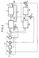
- the air conditioning control system is shown in detail in Figure 3.
- the elements identical to those of Figure 1 are referenced alike.
- the system further comprises a corrector 17 to which the comparator 18 has been incorporated which receives on a first input the set temperature T c .
- the system also includes a model 19 of the conditioning unit receiving on its inputs the same control signals as the conditioning unit 3.
- the model 19 delivers a signal representative of the estimated supply air temperature .
- the model 20 delivers, in response to the quantity representative of the supply air temperature, a signal representative of the air temperature .
- This signal is sent to one of the inputs of comparator 21 which receives on its second input a signal representative of the return air temperature TAR.
- the signal representing the temperature is also addressed to model 19 to perform the "return air" function of the actual process.
- the comparator 21 delivers an output signal which is sent to a second input of the comparator 18 which provides an error signal to the rest of the corrector 17.
- the corrector also receives a signal from the temperature sensor 8.
- a variant of the system consists in having a cascade structure thanks to a comparator 22 receiving on one of its inputs the signal and on another input a signal representing the temperature of air blown into the passenger compartment TAS and supplied by the temperature sensor 9.
- the comparator 22 delivers an error signal which is sent to the corrector 17.
- the corrector 17 comprises two calculation members 23 and 24 separated by a comparator 25.
- the calculation member 23 receives the error signal delivered by the comparator 18 and a signal representative of the fresh air temperature TAN supplied by the sensor 8. It delivers a signal on a first input of the comparator 25 which receives on its second input the error signal supplied by the comparator 22.
- the comparator delivers a signal to the calculation unit 24 which also receives, on another input, the signal from the sensor 8.
- the calculation unit 24 delivers in response the control signals 7.
- the corrector can be of a type known to those skilled in the art. It can be a fixed corrector, a variable corrector over time (its parameters evolving in conjunction with those of the models) or a corrector with predictive control algorithm.
- FIG. 4 illustrates a possible configuration for the model of the conditioning unit, for example for the heating control part, the other parts being identical.
- This part of the model includes three transfer function elements 31, 32 and 33.
- Element 31 receives on its input 35 a signal corresponding to the heating control. Its function is transfer G1. Its output is connected to one of the summing inputs 34.
- the element 32, of transfer function G2 receives on its input 36 the signal (see figure 3). Its output is connected to the second input of the adder 34 whose output is connected to the input of the element 33.
- the element 33 has the function of transfer 1 1+ ⁇ p , p being the time derivation operator. It delivers on its output 37 the signal corresponding to the quantity representative of the supply air temperature of the conditioning unit.
- the parameters a, b and c are experimental values obtained by identification as well as G2 and ⁇ .
- the inputs of the conditioning unit control, return air temperature
- the influence of which is modulated by the coefficients G1 and G2 and by the time constant ⁇ of the system.
- the non-linearity of the thermal system therefore appears through the coefficient G1 which varies over time.
- the system has a third inlet consisting of the temperature of the fresh air.
- This element acts as a simple temperature shift, because, if the system command is zero, the supply air temperature must be at least equal to the air temperature new. Its action is therefore simple to implement and does not present a priori any particular difficulty.
- Figure 5 illustrates a possible configuration for the passenger room model.
- the model includes two transfer function elements 41 and 42.
- the inputs of elements 41 and 42 are addressed by the same signal .
- Their outputs are connected to the inputs of a summator 43 which delivers the signal .
- the parameters x, y, z, w and G'1 come from the identification of the system.
- the passenger room model shows two branches in parallel. The first (coefficient G'2) involves the direct and rapid action of the blown air on the returned air. The second allows to introduce the response time ⁇ 'of all the materials making up the passenger room to a demand for blown air.
- the non-linear model used by the invention makes it possible to take into account the significant difference in dynamics between the temperature increases and decreases as well as a difference between the starting state (activation of the air conditioning) and the 'final state (obtaining the set temperature).
- An important improvement of the air conditioning regulation device of the invention relates to a specific management of the saturation of the regulation control system.
- Such saturation is for example caused by the physical limit of the operating range of the actuators but also by the available power.
- the air conditioning regulation device as described above makes it possible to be free from exceeding the setpoint, but with the drawback of being able to react only with the inherent dynamics of the process, due to the open loop structure of this type of corrector.
- FIG. 6 represents the simplified structure of a rail air conditioning system according to the invention in which appears a branch dedicated to the management of saturation.
- Figure 6 shows the elements shown in Figure 2, namely: a corrector 11 delivering control signals simultaneously to the actual process to be controlled 12 and to a model 13 of the process.
- the set temperature Tc is sent to one of the inputs of the comparator 14, the second input of which receives a signal from the comparator 15.
- the comparator 14 delivers an output signal to the corrector 11.
- the comparator 15 receives on a first input the signal leaving the process 12 (representing the temperature inside the vehicle) and on a second input the signal leaving the model 13 and delivers in response an output signal addressed to the comparator 14.
- the comparator 16 makes it possible to introduce symbolically the influence of the disturbances P due to the external environment as well as to the passengers of the vehicle.
- an element 26, of transfer function, for example, of the type G 1+ ⁇ p receiving the setpoint temperature at its input, makes it possible to deliver a signal representative of the reference trajectory which the output of process 12 must rally.
- the process model In the field of internal model control, the process model must best reproduce the process itself, in particular its non-linearities. When the process model and the process are perfectly identical, the output signal from comparator 15 is constantly zero. The operation is therefore done in open loop. If saturation limits the amplitude of the control signal of process 12 and of model 13 of the process, the dynamic objectives are no longer satisfied. In addition, the closed loop is unable to correct this defect.
- the device has a much slower response than that corresponding to the reference path.
- the second corrector 28 By comparing this reference trajectory to the actual output of the process, the second corrector 28 generates a signal which combined with that of the conventional corrector 11, by means of the comparator 29, makes it possible to combat the disturbance introduced by the non-linearity of the actuator .
- this corrector also makes it possible to combat disturbances in state or structure, in the event of system / model mismatch.
Landscapes
- Engineering & Computer Science (AREA)
- Mechanical Engineering (AREA)
- General Engineering & Computer Science (AREA)
- Chemical & Material Sciences (AREA)
- Combustion & Propulsion (AREA)
- Signal Processing (AREA)
- Physics & Mathematics (AREA)
- Fuzzy Systems (AREA)
- Mathematical Physics (AREA)
- Thermal Sciences (AREA)
- Air Conditioning Control Device (AREA)
- Air-Conditioning For Vehicles (AREA)
Applications Claiming Priority (4)
| Application Number | Priority Date | Filing Date | Title |
|---|---|---|---|
| FR9302111A FR2702034B1 (fr) | 1993-02-24 | 1993-02-24 | Dispositif de régulation de climatisation d'un local fixe ou en mouvement. |
| FR9302111 | 1993-02-24 | ||
| FR9310730 | 1993-09-09 | ||
| FR9310730A FR2702035B1 (fr) | 1993-02-24 | 1993-09-09 | Dispositif de régulation de climatisation d'un local. |
Publications (1)
| Publication Number | Publication Date |
|---|---|
| EP0612964A1 true EP0612964A1 (de) | 1994-08-31 |
Family
ID=26230119
Family Applications (1)
| Application Number | Title | Priority Date | Filing Date |
|---|---|---|---|
| EP94400365A Withdrawn EP0612964A1 (de) | 1993-02-24 | 1994-02-21 | Regelvorrichtung für die Klimatisierung |
Country Status (6)
| Country | Link |
|---|---|
| US (1) | US5557555A (de) |
| EP (1) | EP0612964A1 (de) |
| JP (1) | JP3468816B2 (de) |
| KR (1) | KR100314364B1 (de) |
| CA (1) | CA2116306C (de) |
| FR (1) | FR2702035B1 (de) |
Cited By (3)
| Publication number | Priority date | Publication date | Assignee | Title |
|---|---|---|---|---|
| EP1757476A1 (de) * | 2005-08-25 | 2007-02-28 | Behr GmbH & Co. KG | Verfahren und Vorrichtung zur Regelung eines Klimatisierungssystems für einen Innenraum eines Fahrzeugs |
| FR2993641A1 (fr) * | 2012-07-23 | 2014-01-24 | Peugeot Citroen Automobiles Sa | Dispositif d'estimation indirecte de la temperature dans une enceinte alimentee en air traite par une installation de chauffage/climatisation |
| EP3431893A4 (de) * | 2016-04-08 | 2019-03-13 | Mitsubishi Electric Corporation | Klimaanlagenausblastemperaturschätzungsvorrichtung und -programm |
Families Citing this family (9)
| Publication number | Priority date | Publication date | Assignee | Title |
|---|---|---|---|---|
| JP2765630B2 (ja) * | 1996-05-23 | 1998-06-18 | 東京都地下鉄建設株式会社 | 地下空間における空気調和・換気シミュレータ |
| US6094602A (en) * | 1996-11-29 | 2000-07-25 | Woodward Governor Company | Method and apparatus for estimating and controlling non-linear disturbances in a feedback control system |
| US6092380A (en) * | 1998-11-23 | 2000-07-25 | Delphi Technologies, Inc. | Method for regulating the cooling performance of an air conditioning system |
| US6554198B1 (en) * | 2000-05-05 | 2003-04-29 | Automated Logic Corporation | Slope predictive control and digital PID control |
| DE10261792A1 (de) * | 2002-12-23 | 2004-07-15 | Robert Bosch Gmbh | Klimatisierungsvorrichtung und Verfahren zur Klimatisierung eines begrenzten Volumens |
| US6813895B2 (en) * | 2003-09-05 | 2004-11-09 | Carrier Corporation | Supercritical pressure regulation of vapor compression system by regulation of adaptive control |
| CN101770243B (zh) * | 2009-01-06 | 2012-10-31 | 珠海格力电器股份有限公司 | 空调系统和空调系统的动态调温方法 |
| KR101210097B1 (ko) * | 2010-09-09 | 2012-12-07 | 기아자동차주식회사 | 공조 장치의 제어 방법 |
| JP7231374B2 (ja) * | 2018-10-10 | 2023-03-01 | 大成建設株式会社 | 室内温熱環境解析方法 |
Citations (2)
| Publication number | Priority date | Publication date | Assignee | Title |
|---|---|---|---|---|
| US4784212A (en) * | 1986-11-21 | 1988-11-15 | Transmet Engineering, Inc. | Building perimeter thermal energy control system |
| US4897798A (en) * | 1986-12-08 | 1990-01-30 | American Telephone And Telegraph Company | Adaptive environment control system |
Family Cites Families (3)
| Publication number | Priority date | Publication date | Assignee | Title |
|---|---|---|---|---|
| US4341345A (en) * | 1980-02-19 | 1982-07-27 | Honeywell Inc. | Method and apparatus for power load shedding |
| DE3576314D1 (de) * | 1984-10-19 | 1990-04-12 | Nippon Denso Co | Kraftfahrzeugklimaanlage. |
| US4744511A (en) * | 1985-11-27 | 1988-05-17 | Nippondenso Co., Ltd. | Air conditioner for automobiles |
-
1993
- 1993-09-09 FR FR9310730A patent/FR2702035B1/fr not_active Expired - Fee Related
-
1994
- 1994-02-19 KR KR1019940002999A patent/KR100314364B1/ko not_active Expired - Fee Related
- 1994-02-21 EP EP94400365A patent/EP0612964A1/de not_active Withdrawn
- 1994-02-23 CA CA002116306A patent/CA2116306C/fr not_active Expired - Fee Related
- 1994-02-23 JP JP02504394A patent/JP3468816B2/ja not_active Expired - Fee Related
- 1994-02-23 US US08/200,666 patent/US5557555A/en not_active Expired - Lifetime
Patent Citations (2)
| Publication number | Priority date | Publication date | Assignee | Title |
|---|---|---|---|---|
| US4784212A (en) * | 1986-11-21 | 1988-11-15 | Transmet Engineering, Inc. | Building perimeter thermal energy control system |
| US4897798A (en) * | 1986-12-08 | 1990-01-30 | American Telephone And Telegraph Company | Adaptive environment control system |
Cited By (4)
| Publication number | Priority date | Publication date | Assignee | Title |
|---|---|---|---|---|
| EP1757476A1 (de) * | 2005-08-25 | 2007-02-28 | Behr GmbH & Co. KG | Verfahren und Vorrichtung zur Regelung eines Klimatisierungssystems für einen Innenraum eines Fahrzeugs |
| FR2993641A1 (fr) * | 2012-07-23 | 2014-01-24 | Peugeot Citroen Automobiles Sa | Dispositif d'estimation indirecte de la temperature dans une enceinte alimentee en air traite par une installation de chauffage/climatisation |
| WO2014016485A1 (fr) * | 2012-07-23 | 2014-01-30 | Peugeot Citroen Automobiles Sa | Dispositif d'estimation indirecte de la température dans une enceinte alimentée en air traité par une installation de chauffage/climatisation |
| EP3431893A4 (de) * | 2016-04-08 | 2019-03-13 | Mitsubishi Electric Corporation | Klimaanlagenausblastemperaturschätzungsvorrichtung und -programm |
Also Published As
| Publication number | Publication date |
|---|---|
| KR940020060A (ko) | 1994-09-15 |
| JP3468816B2 (ja) | 2003-11-17 |
| CA2116306A1 (fr) | 1994-08-25 |
| US5557555A (en) | 1996-09-17 |
| FR2702035A1 (fr) | 1994-09-02 |
| JPH06247297A (ja) | 1994-09-06 |
| FR2702035B1 (fr) | 1995-05-12 |
| CA2116306C (fr) | 2007-12-04 |
| KR100314364B1 (ko) | 2001-12-28 |
Similar Documents
| Publication | Publication Date | Title |
|---|---|---|
| EP0612964A1 (de) | Regelvorrichtung für die Klimatisierung | |
| FR2496921A1 (fr) | Procede et dispositif d'asservissement | |
| EP0780253B1 (de) | Klimaanlage, insbesondere für Kraftwagen | |
| FR3087708A1 (fr) | Installation de gestion thermique d'un vehicule | |
| FR2806036A1 (fr) | Regulation perfectionnee de la temperature, de la vitesse et de la distribution de l'air ventile dans un habitacle de vehicule automobile | |
| EP0148700A2 (de) | Verfahren und Vorrichtung zur Regelung für eine Raumheizungsanlage, die mehrere Wärmequellen aufweist | |
| EP0427585B1 (de) | Steuervorrichtung und Arbeitszyklus für die Durchflussregeleinrichtung der Lüftung eines Raumes mit kontrollierter Atmosphäre | |
| FR2743027A1 (fr) | Dispositif de climatisation de l'habitacle d'un vehicule | |
| FR2780919A1 (fr) | Dispositif de commande du fonctionnement d'un systeme de ventilation/climatisation de l'habitacle d'un vehicule automobile | |
| FR2503056A1 (fr) | Installation de ventilation de vehicule | |
| EP2651674B1 (de) | System und verfahren zur steuerung eines klimaanlagensystems für ein kraftfahrzeug | |
| FR2702034A1 (fr) | Dispositif de régulation de climatisation d'un local fixe ou en mouvement. | |
| EP4522435B1 (de) | Verfahren und system zur regelung des beschlagens auf der innenfläche mindestens einer verglasungseinheit eines fahrzeugs | |
| EP2197698B1 (de) | Verbesserte fahrzeugklimaanlage mit automatischen betriebsarten | |
| EP3003750A1 (de) | Vorrichtung zur indirekten ermittlung der temperatur in einem durch eine heiz-/klimatisierungsvorrichtung gekühlten gehäuse | |
| FR2816699A1 (fr) | Enceinte frigorifique amovible et transportable dans un vehicule | |
| EP0140734B1 (de) | Zwischenglied zur Steuerung und Regelung von Temperatur und Feuchtigkeit | |
| EP3919339B1 (de) | Klimatisierungssystem für einen innenraum eines fahrzeugs, entsprechendes fahrzeug und anwendungsverfahren | |
| EP0521756A1 (de) | Selbsttätige Vorrichtung zur Frischluftregulierung eines Wageninneren | |
| EP0234999B1 (de) | Steuerungsvorrichtung für die Klimaanlage eines Kraftfahrzeuges | |
| EP2150425A1 (de) | Klimatisierungssystem für ein fahrzeug mit vorrichtung zur erreichung eines temporären leistungsüberschusses beim laden eines einstellwertes für eine klimatisierungskomfortstufe | |
| EP2655107B1 (de) | Mit einem system und verfahren für den betrieb einer elektrischen heizkomponente ausgestattetes kraftfahrzeug | |
| EP1258376B1 (de) | Verfahren zum Regulieren der thermischen Energie von Luft die in einem klimatisierten Fahrzeug-Innenraum ausgeblasen wird | |
| FR2741303A1 (fr) | Installation de chauffage-climatisation, notamment d'habitacle de vehicule automobile | |
| FR2737444A1 (fr) | Installation de chauffage et/ou climatisation, notamment d'habitacle de vehicule automobile |
Legal Events
| Date | Code | Title | Description |
|---|---|---|---|
| PUAI | Public reference made under article 153(3) epc to a published international application that has entered the european phase |
Free format text: ORIGINAL CODE: 0009012 |
|
| AK | Designated contracting states |
Kind code of ref document: A1 Designated state(s): BE DE ES FR GB IT SE |
|
| 17P | Request for examination filed |
Effective date: 19941212 |
|
| 17Q | First examination report despatched |
Effective date: 19960115 |
|
| STAA | Information on the status of an ep patent application or granted ep patent |
Free format text: STATUS: THE APPLICATION IS DEEMED TO BE WITHDRAWN |
|
| 18D | Application deemed to be withdrawn |
Effective date: 19970327 |