EP0613112A2 - Anzeigehalter - Google Patents
AnzeigehalterInfo
- Publication number
- EP0613112A2 EP0613112A2 EP94301390.4A EP94301390A EP0613112A2 EP 0613112 A2 EP0613112 A2 EP 0613112A2 EP 94301390 A EP94301390 A EP 94301390A EP 0613112 A2 EP0613112 A2 EP 0613112A2
- Authority
- EP
- European Patent Office
- Prior art keywords
- display holder
- center panel
- frame
- flange
- web
- Prior art date
- Legal status (The legal status is an assumption and is not a legal conclusion. Google has not performed a legal analysis and makes no representation as to the accuracy of the status listed.)
- Granted
Links
- 238000001125 extrusion Methods 0.000 claims abstract description 14
- 239000004033 plastic Substances 0.000 claims abstract description 14
- 229920003023 plastic Polymers 0.000 claims abstract description 14
- 238000010276 construction Methods 0.000 claims description 5
- 238000003780 insertion Methods 0.000 claims description 3
- 230000037431 insertion Effects 0.000 claims description 3
- 239000000463 material Substances 0.000 claims description 3
- 229920002457 flexible plastic Polymers 0.000 claims 1
- 238000000034 method Methods 0.000 abstract description 4
- 238000005452 bending Methods 0.000 description 2
- 230000006378 damage Effects 0.000 description 2
- 238000002347 injection Methods 0.000 description 2
- 239000007924 injection Substances 0.000 description 2
- 239000003973 paint Substances 0.000 description 2
- 241000167857 Bourreria Species 0.000 description 1
- 208000027418 Wounds and injury Diseases 0.000 description 1
- 230000000712 assembly Effects 0.000 description 1
- 238000000429 assembly Methods 0.000 description 1
- 210000000988 bone and bone Anatomy 0.000 description 1
- 208000014674 injury Diseases 0.000 description 1
- 239000002184 metal Substances 0.000 description 1
- 125000006850 spacer group Chemical group 0.000 description 1
- 229920002725 thermoplastic elastomer Polymers 0.000 description 1
- 239000002023 wood Substances 0.000 description 1
Images



Definitions
- This invention relates to display holders for sign boards, paint samples, etc. More particularly, it relates to the provision of improved display boards which are adapted to be mounted in a vertical orientation, by a structure which permits a swinging movement of the sign board about a generally vertical axis.
- U.S. Patent No. 4,805,331 discloses a display holder that is adapted to be mounted onto the front of a store shelf by a structure which holds the display holder in a yertical orientation and in a position that is generally perpendicular to the front edge of a shelf, but which allows the display holder to pivotally move out of the way of a customer or article that strikes it.
- the display holder includes a bias means which automatically returns it to its normal position when the force causing it to swing has been removed. This ensures that the advertising message or display continuously remains in a direct view of approaching customers.
- An object of the present invention is to provide a display holder capable of performing the function of the display holder disclosed in U.S. Patent No. 4,805,331, but which is much simpler in construction.
- U.S. Patent No. 4,881,707 discloses a display holder similar to the display holder disclosed by U.S. Patent No. 4,805,331, except it includes a hinge comprised of a plurality of stria which are formed from a flexible material such as thermoplastic elastomer.
- An object of the present invention is to provide an improved construction of the display holder and a flexible strip hinge which is selectively usable with the display holder for better serving the objectives of the display holder and hinge disclosed by U.S. Patent No. 4,881,707.
- Another object of the present invention is to provide a mounting structure for the display holder which both structurally reinforces a frame member of the display holder and provides a support for upper and lower trunnions which are used to mount the display holder for pivotal movement about a vertical axis.
- a display holder which is basically characterized by a center panel having two side faces, two side edges, a top edge and a bottom edge.
- a first frame portion is at the first side edge.
- a second frame portion is at the second side edge.
- a third frame portion is at the top edge.
- a fourth frame portion is at the bottom edge.
- An opposite edge pair of frame portions form with the center panel a pair of confronting channels which receive mounting portions of a display. At least one of the remaining two frame portions is removable to permit insertion of a display into or removal of a display out from the channels.
- the opposite edge frame portions are formed integral with the center panel.
- these frame portions and the center panel are a single extrusion.
- the remaining two frame members are detachable from the center panel and include channels for snugly receiving end portions of the center panel. These frame portions may be injection molded.
- the first edge frame portion is formed integral with the center panel and comprises a base strip which extends perpendicular to the center panel.
- the base strip has opposite side edges.
- a first flange is connected to the first side edge of the base strip.
- a second flange is connected to the second side edge of the base strip.
- the flanges extend from the base strip in a direction generally opposite the center panel.
- a first lip extends laterally inwardly from the first flange.
- a second lip extends laterally inwardly from the second flange.
- the lips are spaced from the base strip.
- the base strip, the flanges and the lips together form a channel space for receiving a flange portion of a mounting member.
- a mounting member which is in the nature of an elongated extrusion.
- This mounting member comprises a first flange sized to be received within the channel space of the first edge frame portion, a second flange spaced from the first flange, and an interconnecting web.
- the first and second flanges are formed of a relatively rigid structural plastic.
- the web is formed from a resilient structural plastic and functions as a hinge.
- the second flange of the mounting member is connected to a shelf or frame member.
- the display holder extends generally perpendicular to the front edge of a shelf or frame member.
- the hinge strip allows the display holder to pivotally move out of the way of a customer or article that strikes it. The hinge strip automatically returns the display holder to its normal at rest position when the force causing it to swing has been removed.
- a mounting member which comprises a flange that is slidable into the channel space of the first edge frame portion and a longitudinally split tubular rib. Each end of this tubular rib receives a trunnion having an outer end part which projects beyond its end of the display holder. The trunnions fit into aligned openings in spaced apart members which are secured to a shelf end wall, a frame member, or the like.
- This type of mounting may be used to mount a plurality of display holders relatively close together, each for pivotal movement about a separate vertical axis.
- the first frame portion includes a pair of frame flanges, on opposite sides of the panel.
- the frame flanges extend from the base strip in the same direction as the center panel.
- Each frame flange is spaced from the center panel so as to with the center panel form a vertically extending channel.
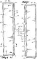
- the display holder of the present invention comprises a main member 10 that is preferably an extrusion.
- Main member 10 includes a center panel 12 having a first side face 14 and a second side face 16.
- Center panel 12 also includes a first side edge 18, a second side edge 20, a third edge 22 at its top (Fig. 9) and a fourth edge 24 at its bottom (Fig. 10).
- Edges 18, 20 are sometimes referred to as first and second opposite edges. This is because they are at opposite side edge boundaries of the center panel 12.
- Edges 22 and 24 are sometimes referred to as third and fourth opposite edges. This is because they are at opposite end boundaries of the center panel 12.
- the extrusion which includes center panel 12 also includes first and second frame portions 28, 30.
- Frame portion 28 includes a base strip 32 which extends perpendicular to center panel 12.
- base strip 32 projects outwardly, an equal amount on each side of the center panel 12.
- a first flange 34 is connected to a first edge of base strip 32.
- a second flange 36 is connected to the second edge of base strip 32.
- the flanges 34, 36 are parallel to each other and both extend from the base strip 32 in a direction opposite from center panel 12.
- a first lip 38 is connected to flange 34.
- a second lip 40 is connected to flange 36. Lips 38, 40 are coplanar with each other and are in laterally spaced parallelism with base strip 32.
- Base strip 32, flanges 34, 36 and lips 38, 40 together form a lipped channel in which one flange 42 of a mounting member 44 is received.
- the lipped channel opens edgewise outwardly of the center panel 12.
- Frame portion 28 includes a pair of frame flanges 46, 48 which project from base strip 32, in a laterally spaced relationship with the center panel 12.
- Frame flanges 46, 48 extend parallel to each other and to the center panel 12.
- a channel 50 is formed by and between center panel 12 and frame flange 46.
- a channel 52 is formed by and between center panel 12 and frame flange 48.
- Frame portion 30 comprises a cap strip 54 and a pair of frame flanges 56, 58.
- Cap strip 54 is generally semi-annular in cross-sectional shape.
- Frame flange 56 extends from cap strip 54 in a laterally spaced relationship with center panel 12.
- Frame flange 58 also extends from cap strip 54 in a laterally spaced relationship from center panel 12, but on the opposite side of the center panel 12 from frame flange 56.
- Frame flanges 56, 58 extend parallel to each other and to the center panel 12.
- a channel 60 is formed by and between center panel and frame flange 56.
- a channel 62 is formed by and between center panel 12 and frame flange 58.
- channel 60 confronts channel 50 on a first side of center panel 12.
- Channel 62 confronts channel 52 on the opposite side of center panel 12.
- the channels 50, 60 and 52, 62 receive side edge portions of a article or articles to be displayed.
- a plastic or cardboard sign board may be slid endwise of the display holder, with its opposite edge portions within channels 50, 60.
- a duplicate of this display board can be located in channels 52, 62 on the opposite side of display holder 10.
- a plurality of strips of wood, each bearing a different paint sample can be slid into the channels 50, 60 and/or 52, 62.
- Frame portions 64, 66 may be injection molded from a suitable structural plastic. As shown by Figs. 9 and 10, frame portions 64, 66 comprise cap strips 68, 70 which are like cap strip 54, in cross-sectional configuration. However, they include flanges 72, 74 and 76, 78 which are parallel to each other and laterally spaced apart a distance substantially equal to the thickness of center panel 12. As shown by Fig. 9, the upper edge portion of center panel 12 is snugly fitted in a channel formed by and between flanges 72, 76. As shown by Fig. 10, a lower end portion of center panel 12 is snugly fitted within a channel formed by and between flanges 56, 78.
- Fig. 11 is a top plan view of frame portion 66. It is also a bottom plan view of frame portion 64 because frame portions 64, 66 are identical in construction. In Fig. 11, the channel in which the lower end portion of center panel 12 is received is designated 80.
- Frame portion 64 includes a like end region 84.
- the opposite end of frame portion 66 includes a tongue 86 which extends downwardly into the lipped channel formed by base strip 32, flanges 34, 36 and lips 38, 40. It also includes a space 88 in which is received a central end portion of base strip 32, when frame portion 66 is connected to the lower edge portion of center panel 12.
- Mounting member 44 is shorter in length than base strip 32.
- mounting member 44 The opposite ends of mounting member 44 are spaced endwise inwardly of frame portions 64, 66, to allow entry of the end portions of mounting strip 32 into the space 88 in frame portion 66, and into a like space in frame member 66.
- the end portions of center panel 12 are snugly received between the flanges 72, 74 at the top and 76, 78 at the bottom.
- the frame portions 64, 66 are frictionally connected to the ends of the main member 10.
- the frame portions 64, 66 when the frame portions 64, 66 are in place, they form end closures for the channels 50, 60 and 52, 62.
- Mounting member 74 includes flange 42, a base flange 90 and a web 92.
- Base flange 90 includes a base wall 94 that is in spaced parallelism with flange 42.
- Wall 94 extends perpendicular to web 92.
- Flanges 96, 98 extend from wall 94 in a direction opposite web 92.
- Flanges 96, 98 are parallel to each other and are perpendicular to wall 94.
- Lips 100, 102 extend inwardly from flanges 96, 98. Lips 100, 102 are in coplanar parallelism. They are also in spaced parallelism with wall 94.
- Wall 94, flanges 96, 98 and lips 100, 108 together form a lipped channel 104 which extends the full length of the mounting member 44.
- mounting member 44 is manufactured by a co-extrusion process.
- die cavities 42c, 90c, 92c are formed in an extrusion die ED.
- a first structural plastic "A” is introduced into cavities 42c and 90c while a second plastic “B” is introduced into cavity 92c.
- the two plastics "A” and “B” bond together as they move through the die ED.
- Plastic "A” is a relatively strong and rigid structural plastic, e.g. rigid PVC.
- Plastic "B” is a strong but resilient plastic, e.g. resilient PVC. It is bendable but returns to its at rest shape when the bending force is removed from it. Referring to Fig.
- hinge strip 96 is in the nature of a spring. It is bendable but as it bends it stores spring energy. When the bending force is removed, the spring energy moves the hinge strip 96 back into its at rest position.
- the at rest position has the display holder 10 extending generally perpendicular to the member to which mounting flange 90 is connected.
- an elongated tongue portion 106 of a connector 108 may fit snugly within lipped channel 104.
- a set screw 110 may be threaded into a threaded opening in the tongue 106.
- Set screw 110 can be rotated clockwise to exert a locking force against wall 94 of lip channel 104. In this manner the set screw 110 holds the connector 108 firmly to the mounting member 44.
- Connector 108 extends upwardly and rearwardly from tongue 106 and then downwardly as a rear leg 112. It then extends horizontally as a mounting leg 114.
- the mounting leg 114 may be set down on a shelf and screw fasteners (not shown) may be inserted through openings 116 and used to firmly connect the connector 108 to the shelf.
- screw fasteners not shown
- other methods of attaching the display holder 10 to a shelf or other support member may be employed.
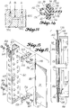
- Figs. 15-17 relate to a modified embodiment of the invention in which the mounting member 44 is replaced by a different style of mounting member 118.
- Mounting member 118 has a uniformed cross section throughout its length (Fig. 16). It is equal in length to mounting member 44.
- Mounting member 118 includes a flange 120 that is like flange 42. Flange 120 fits snugly within the lipped channel in frame portion 28 formed by the base strip 32, the flanges 34, 36 and the lips 38, 40 (Fig. 16).
- Mounting member 118 also includes a slotted, tubular rib 130. Rib 130 is substantially annular in cross section but includes a slot 132 which extends the full length of rib 130. It also includes a center opening 134.
- Rib 130 provides a strong back bone for the mounting member 118. It also provides mounting sockets for a pair of trunnions 136, 138. Each trunnion 136, 138 includes an enlargement 140, 142 which divides it between inner and outer parts. Each inner part 144, 146 fits snugly within the opening 134 at one end of the rib 130. The enlargements 140, 142 fit against the end surface of the rib 130 and prevent movement of the trunnion 136, 138 into the opening 134 beyond the location of enlargement 140, 142. The outer or outboard portions 148, 150 of the trunnions 136, 138 each extend coaxial with the other.
- the outboard end portion 148 of trunnion 136 extends through an opening 152 in an upper mounting bracket 154. Specifically, opening 152 is in a horizontal leg of the bracket 154. The outboard end portion 150 of trunnion 138 fits within an opening 156 in a second bracket 158. As shown by Fig. 15, opening 156 is in a horizontal leg of bracket 158. Brackets 154, 156 are secured to a frame member 160, by fastener assemblies including bolts 162, washers 164 and nuts 166, as shown in Fig. 15.
- the opening 134 is slightly smaller in diameter than the diameter of end parts 144, 146 of the trunnions 136, 138. Thus, it is necessary to force the end parts 144, 146 into the ends of the opening 134. This is permitted by the slot 132. It allows the side portions of the rib 130, on opposite sides of slot 132, to spread apart slightly as the trunnions are forced inwardly. This makes the side portions act as springs or clamps. They firmly grip and hold the end portions 144, 146 of the trunnions 136, 138.
- the lower enlargement 142 also acts as an end bearing, where it bears against the metal surrounding opening 146.
- the horizontal legs of the brackets 154, 158 may be provided with a plurality of laterally spaced apart openings. In the illustrated example, five openings are shown. This permits the mounting of five display holders 10, as a group, between the two brackets 154, 158. Other ways of mounting the display holder may be used. Also, the configuration of the display holder may vary from what is illustrated.
- the corners 82, 84 are rounded and the frame portions 30, 64, 66 are rounded in the lateral direction. This provides a surface which is not apt to cause any injury if struck by a person or any damage to an object that may be accidently moved in contact with the display holder 10.
- the illustrated display holders are vertically elongated. However, certain aspects of the invention could be used with advantage within a display holder that is horizontally elongated. For example, the construction of the display holder from a single extrusion main member, including a center panel and opposite edge frame portions, together with detachable frame members for the other pair of opposite edges.
- Figs. 18-20 illustrate the mounting bracket that may be used for securing the first embodiment (Figs. 1-13) to a horizontal frame member or beam 170.
- Beam 170 may be like frame member 160 shown in Fig. 15.
- the mounting member 172 would be used in place of the connector 108.
- Mounting member 172 comprises a first part 174 and a second part 176.
- Part 174 has a vertical wall 176, a top wall 178 and a flange 180.
- Flange 180 depends from top wall 178 and is parallel to wall 176.
- the second part 176 includes a vertical wall 182 and a bottom wall 184. Walls 182, 184 are perpendicular to each other.
- Walls 176, 178 are perpendicular to each other and flange 180 is perpendicular to wall 178. As illustrated, wall 176 side laps wall 182. Wall 176 includes a vertical slot 186 and wall 182 includes a vertical slot 188. Each slot 186, 188 is closed at both of its ends. Slots 186, 188 are in alignment with each other, as best shown by Fig. 19.
- a screw fastener 190 extends through the two slots 186, 188. Screw fastener 190 includes a head 200 that is larger in diameter than the slots 186, 188 are wide. Screw 190 threads into a nut 200. The screw fastener 190 is screwed tight into the nut 200 so that it clamps the two members 176, 182 together.
- Member 176 may include a pair of side flanges 206, 208 between which the vertical leg of member 176 is received. Flanges 206, 208 contact the opposite edges 210, 212 of vertical wall 176, to prevent member 172 from rotating in position relative to member 176, about the axis of the fastener screw 190.
- a spacer rod 214 is secured to the member 176. Rod 214 includes a horizontal leg 216 and a vertical leg 218. These legs 214, 216 are spot welded to member 176, at 220, 222, 224 and 226.
- a flat bar 228 is welded to rod parts 216, 218 at 222 and 230.
- Flat bar 228 forms a flange that is sized and shaped to fit snugly within the lipped channel 104, in place of tongue 106.
- Bar 228 includes a threaded opening 232 which receives a set screw, like set screw 110. This set screw is used to firmly anchor the bar 228 in position relative to channel member 90 of mounting member 44.
- Members 174, 176 are brought together about the beam 170. Then, the screw fastener 190 is tightened within nut 202, to firmly clamp members 174, 176 together.
- the square nature of the four corners of beam 170, the two corners of member 172 and the lower left (as pictured) corner of member 176 result in member 172 being firmly secured to the beam 170, and restrained against movement in essentially all directions.
- This clamping of the members 174, 176 together, and to the beam 170 provides a definite vertical placement of the member 228.
- Bar portion 218 provides a proper lateral spacing of flat bar 228 from vertical walls 176, 182.
- Member 218 is also sized to fit within the open region of the channel 104, between the two lips 100, 102.
Applications Claiming Priority (2)
| Application Number | Priority Date | Filing Date | Title |
|---|---|---|---|
| US08/023,694 US5419134A (en) | 1993-02-26 | 1993-02-26 | Display holder |
| US23694 | 1993-02-26 |
Publications (4)
| Publication Number | Publication Date |
|---|---|
| EP0613112A2 true EP0613112A2 (de) | 1994-08-31 |
| EP0613112A1 EP0613112A1 (de) | 1994-08-31 |
| EP0613112A3 EP0613112A3 (de) | 1996-08-28 |
| EP0613112B1 EP0613112B1 (de) | 1999-01-27 |
Family
ID=21816681
Family Applications (1)
| Application Number | Title | Priority Date | Filing Date |
|---|---|---|---|
| EP94301390A Expired - Lifetime EP0613112B1 (de) | 1993-02-26 | 1994-02-28 | Anzeigehalter |
Country Status (6)
| Country | Link |
|---|---|
| US (1) | US5419134A (de) |
| EP (1) | EP0613112B1 (de) |
| AU (1) | AU674720B2 (de) |
| CA (1) | CA2116508C (de) |
| DE (1) | DE69416175T2 (de) |
| DK (1) | DK0613112T3 (de) |
Families Citing this family (28)
| Publication number | Priority date | Publication date | Assignee | Title |
|---|---|---|---|---|
| US5448845A (en) * | 1993-02-26 | 1995-09-12 | Burke Gibson, Inc. | Frame piece for display holder |
| US6533134B1 (en) * | 1994-05-27 | 2003-03-18 | Trademark Properties, Llc | Merchandising display system |
| US5579599A (en) * | 1994-12-08 | 1996-12-03 | Neem, Inc. | One-piece display sign |
| US5513048A (en) * | 1995-04-27 | 1996-04-30 | Chen; Ming-En | Telescopic side view mirror for automobiles |
| US5722623A (en) * | 1996-09-18 | 1998-03-03 | Burke Gibson, Inc. | Upright display assembly |
| US5987794A (en) * | 1997-02-28 | 1999-11-23 | Lavi Industries | Sign with replacement insert |
| US5933994A (en) * | 1997-06-19 | 1999-08-10 | Russell & Miller, Inc. | Retail checkout divider adapted to receive strips with indicia displayed thereon |
| US5933992A (en) * | 1998-03-24 | 1999-08-10 | Cormark, Inc. | Cam locking sign mounting system |
| US6108956A (en) * | 1998-04-03 | 2000-08-29 | Cormark, Inc. | Tri-mount sign system |
| US6434871B2 (en) | 1998-04-03 | 2002-08-20 | Cormark, Inc. | Shelf-mount sign system |
| US6206212B1 (en) * | 1999-01-05 | 2001-03-27 | Design Display Group, Inc. | Display unit |
| US6363643B1 (en) * | 2000-03-24 | 2002-04-02 | Cormark, Inc. | Adjustable sign mount with graphic |
| US6374523B1 (en) | 2000-07-05 | 2002-04-23 | Richard Smith | Holder for mounting to a surface and interchangeably displaying a sheet of material |
| USD451555S1 (en) | 2000-07-05 | 2001-12-04 | Richard Smith | Set of components for a drop-in nameplate |
| US6658776B1 (en) * | 2001-02-13 | 2003-12-09 | Storeimage Programs Inc. | Modular bulkhead display system |
| USD509543S1 (en) * | 2004-08-03 | 2005-09-13 | Marketing Displays, Inc. | Sign frame |
| US7412791B2 (en) | 2004-12-20 | 2008-08-19 | Lsi Industries, Inc. | Adjustable menu panel |
| EP1952371A2 (de) * | 2005-11-09 | 2008-08-06 | Micro Target Media Holdings Inc. | Reklameanzeige für eine tragbare struktur |
| US20070256341A1 (en) * | 2006-05-03 | 2007-11-08 | Postpal, Llc | Post-mountable media display system |
| US20100096347A1 (en) * | 2008-10-16 | 2010-04-22 | Travis Theobald | Apparatus, System, and Method for Selectively Mounting a Hitch Mount Rack on a Building Wall |
| US8230628B2 (en) * | 2010-03-03 | 2012-07-31 | Meadow Burke, Llc | Apparatus and method for attaching signs to concrete road barriers |
| USD692498S1 (en) * | 2012-10-25 | 2013-10-29 | IFCO Systems US, LLC | Swing banner for a tray |
| US9206827B2 (en) | 2012-11-20 | 2015-12-08 | Avery Dennison Corporation | Wall mount organization system |
| US8782936B2 (en) | 2012-12-12 | 2014-07-22 | Target Brands, Inc. | End frame for display structure |
| USD703744S1 (en) * | 2013-06-20 | 2014-04-29 | 3M Innovative Properties Company | Organizer |
| DE102015103292A1 (de) * | 2015-03-06 | 2016-09-08 | Phoenix Contact Gmbh & Co. Kg | Schildträger zum Tragen eines Kennzeichnungsschildes |
| DE102015103294A1 (de) * | 2015-03-06 | 2016-09-08 | Phoenix Contact Gmbh & Co. Kg | Schildträger zum Tragen eines Kennzeichnungsschildes insbesondere mit einem Radiofrequenz-Transponder |
| US10722050B1 (en) * | 2019-08-15 | 2020-07-28 | Target Brands, Inc. | Retail display unit with mounting bracket assembly |
Family Cites Families (29)
| Publication number | Priority date | Publication date | Assignee | Title |
|---|---|---|---|---|
| US1559010A (en) * | 1924-02-04 | 1925-10-27 | Schwieger George Ben | Motion and direction signal for automobiles |
| US1793563A (en) * | 1929-09-11 | 1931-02-24 | Ketterlinus Lithographic Mfg C | Cardboard display device |
| US1866723A (en) * | 1931-07-23 | 1932-07-12 | Glascraft Corp | Bracket for signs and the like |
| US2646241A (en) * | 1948-04-19 | 1953-07-21 | John C Hockery | Takedown type swingable wall bracket |
| US2787433A (en) * | 1954-06-18 | 1957-04-02 | Shaw And Slavsky Inc | Self-stopping hinged sign |
| US3102351A (en) * | 1960-11-30 | 1963-09-03 | Arlington Aluminum Co | Double-sided poster holder |
| US3529798A (en) * | 1967-08-30 | 1970-09-22 | Donald C Williams | Sign assembly |
| FR2132918A5 (de) * | 1971-04-01 | 1972-11-24 | Largillier Ets | |
| US3740881A (en) * | 1971-06-16 | 1973-06-26 | Display Corp Int | Placard holding display assembly |
| US3969838A (en) * | 1975-08-13 | 1976-07-20 | Dayton-Hudson Corporation | Sign |
| USRE30734E (en) * | 1978-10-26 | 1981-09-08 | Dlm, Inc. | Revolving self-service display stand |
| US4344244A (en) * | 1980-06-12 | 1982-08-17 | Tyke Charles R | Signage system and method of making same |
| US4574507A (en) * | 1981-12-15 | 1986-03-11 | Elliott Paul G | Street sign adaptor unit and assembly including the same |
| US4805331A (en) * | 1982-01-10 | 1989-02-21 | Comark Merchandising, Inc. | Pivotable display and dispensing apparatus |
| US4531311A (en) * | 1983-06-23 | 1985-07-30 | Marlboro Marketing, Inc. | Data information display device |
| US4616799A (en) * | 1984-04-25 | 1986-10-14 | Gte Products Corporation | Automatic recovery swing sign structure |
| US4729183A (en) * | 1984-09-20 | 1988-03-08 | Kroy Inc. | Modular frame structure |
| US4593486A (en) * | 1984-12-27 | 1986-06-10 | Plasti-Line, Inc. | Menu and prices display device |
| NL8500404A (nl) * | 1985-02-13 | 1986-09-01 | Alrec Lichtreklame B V | Dialichtbak. |
| US4821437A (en) * | 1985-04-04 | 1989-04-18 | Abramson Patrick B | Merchandise information system |
| US4709891A (en) * | 1986-01-02 | 1987-12-01 | Chicago Show Printing Co. | Support bracket for signs and advertising displays |
| DE3614351A1 (de) * | 1986-04-28 | 1987-11-05 | Esselte Meto Int Gmbh | Preisschild |
| US4866867A (en) * | 1987-08-31 | 1989-09-19 | General Telephone Company Of California | Card holder assembly for paystations |
| US4884351A (en) * | 1988-05-31 | 1989-12-05 | Abramson Marc D | Reflective sign |
| US4881707A (en) * | 1989-02-23 | 1989-11-21 | Clamp Swing Pricing Co. | Sign holder device |
| US4909464A (en) * | 1989-07-10 | 1990-03-20 | Henschel-Steinau, Inc. | Deflectable price channel-mounted sign holder |
| US4957256A (en) * | 1989-12-04 | 1990-09-18 | Oscar Mayer Foods Corporation | Price tag display holder and support arm |
| US5111606A (en) * | 1990-06-11 | 1992-05-12 | Reynolds Randy B | At-shelf lighted merchandising display |
| US5189822A (en) * | 1990-08-24 | 1993-03-02 | Carsonite International | Tamper resistant sign |
-
1993
- 1993-02-26 US US08/023,694 patent/US5419134A/en not_active Expired - Fee Related
-
1994
- 1994-02-25 AU AU56374/94A patent/AU674720B2/en not_active Ceased
- 1994-02-25 CA CA002116508A patent/CA2116508C/en not_active Expired - Fee Related
- 1994-02-28 DK DK94301390T patent/DK0613112T3/da active
- 1994-02-28 EP EP94301390A patent/EP0613112B1/de not_active Expired - Lifetime
- 1994-02-28 DE DE69416175T patent/DE69416175T2/de not_active Expired - Fee Related
Similar Documents
| Publication | Publication Date | Title |
|---|---|---|
| EP0613112B1 (de) | Anzeigehalter | |
| EP0613112A2 (de) | Anzeigehalter | |
| US5560131A (en) | Adjustable, upright display holder | |
| US4677794A (en) | Support assembly for a shelf or like structure | |
| US4154356A (en) | Modular container | |
| US4693380A (en) | Rack support | |
| US7681857B2 (en) | Portable sign and barricade assemblies and plastic molded uprights and light and flag mounts therefor | |
| US5579599A (en) | One-piece display sign | |
| US3936968A (en) | Adjustable frame | |
| US4793083A (en) | Sign holder | |
| US3613900A (en) | Constructional systems | |
| US4804159A (en) | Shelf bracket | |
| US4318528A (en) | Mounting device for plates | |
| US5515630A (en) | Adjustable picture frame | |
| CA1054569A (en) | Article support and display assembly | |
| US6796064B2 (en) | Display | |
| US4635372A (en) | Apparatus for positioning an electrical box | |
| US20020139024A1 (en) | Device for displaying messages | |
| US2867918A (en) | Bracket means for displaying globes, maps, and the like from wall rails | |
| US5448845A (en) | Frame piece for display holder | |
| US4362285A (en) | Channel mounting hook support | |
| US20050050783A1 (en) | Cubicle top nametag display unit | |
| US3313513A (en) | Literature display and dispensing rack | |
| US5515629A (en) | Poster frame and method for framing a poster | |
| CA2202078C (en) | Improved frame piece for display holder |