EP0613210A2 - Installation pour un actionneur - Google Patents
Installation pour un actionneur Download PDFInfo
- Publication number
- EP0613210A2 EP0613210A2 EP94101965A EP94101965A EP0613210A2 EP 0613210 A2 EP0613210 A2 EP 0613210A2 EP 94101965 A EP94101965 A EP 94101965A EP 94101965 A EP94101965 A EP 94101965A EP 0613210 A2 EP0613210 A2 EP 0613210A2
- Authority
- EP
- European Patent Office
- Prior art keywords
- housing
- actuator
- connection
- control line
- contact
- Prior art date
- Legal status (The legal status is an assumption and is not a legal conclusion. Google has not performed a legal analysis and makes no representation as to the accuracy of the status listed.)
- Withdrawn
Links
Images



Classifications
-
- H—ELECTRICITY
- H01—ELECTRIC ELEMENTS
- H01R—ELECTRICALLY-CONDUCTIVE CONNECTIONS; STRUCTURAL ASSOCIATIONS OF A PLURALITY OF MUTUALLY-INSULATED ELECTRICAL CONNECTING ELEMENTS; COUPLING DEVICES; CURRENT COLLECTORS
- H01R4/00—Electrically-conductive connections between two or more conductive members in direct contact, i.e. touching one another; Means for effecting or maintaining such contact; Electrically-conductive connections having two or more spaced connecting locations for conductors and using contact members penetrating insulation
- H01R4/24—Connections using contact members penetrating or cutting insulation or cable strands
- H01R4/2416—Connections using contact members penetrating or cutting insulation or cable strands the contact members having insulation-cutting edges, e.g. of tuning fork type
- H01R4/242—Connections using contact members penetrating or cutting insulation or cable strands the contact members having insulation-cutting edges, e.g. of tuning fork type the contact members being plates having a single slot
- H01R4/2425—Flat plates, e.g. multi-layered flat plates
- H01R4/2429—Flat plates, e.g. multi-layered flat plates mounted in an insulating base
-
- H—ELECTRICITY
- H01—ELECTRIC ELEMENTS
- H01R—ELECTRICALLY-CONDUCTIVE CONNECTIONS; STRUCTURAL ASSOCIATIONS OF A PLURALITY OF MUTUALLY-INSULATED ELECTRICAL CONNECTING ELEMENTS; COUPLING DEVICES; CURRENT COLLECTORS
- H01R12/00—Structural associations of a plurality of mutually-insulated electrical connecting elements, specially adapted for printed circuits, e.g. printed circuit boards [PCB], flat or ribbon cables, or like generally planar structures, e.g. terminal strips, terminal blocks; Coupling devices specially adapted for printed circuits, flat or ribbon cables, or like generally planar structures; Terminals specially adapted for contact with, or insertion into, printed circuits, flat or ribbon cables, or like generally planar structures
- H01R12/50—Fixed connections
- H01R12/59—Fixed connections for flexible printed circuits, flat or ribbon cables or like structures
- H01R12/65—Fixed connections for flexible printed circuits, flat or ribbon cables or like structures characterised by the terminal
- H01R12/67—Fixed connections for flexible printed circuits, flat or ribbon cables or like structures characterised by the terminal insulation penetrating terminals
- H01R12/675—Fixed connections for flexible printed circuits, flat or ribbon cables or like structures characterised by the terminal insulation penetrating terminals with contacts having at least a slotted plate for penetration of cable insulation, e.g. insulation displacement contacts for round conductor flat cables
-
- H—ELECTRICITY
- H01—ELECTRIC ELEMENTS
- H01R—ELECTRICALLY-CONDUCTIVE CONNECTIONS; STRUCTURAL ASSOCIATIONS OF A PLURALITY OF MUTUALLY-INSULATED ELECTRICAL CONNECTING ELEMENTS; COUPLING DEVICES; CURRENT COLLECTORS
- H01R4/00—Electrically-conductive connections between two or more conductive members in direct contact, i.e. touching one another; Means for effecting or maintaining such contact; Electrically-conductive connections having two or more spaced connecting locations for conductors and using contact members penetrating insulation
- H01R4/24—Connections using contact members penetrating or cutting insulation or cable strands
- H01R4/2416—Connections using contact members penetrating or cutting insulation or cable strands the contact members having insulation-cutting edges, e.g. of tuning fork type
- H01R4/242—Connections using contact members penetrating or cutting insulation or cable strands the contact members having insulation-cutting edges, e.g. of tuning fork type the contact members being plates having a single slot
- H01R4/2425—Flat plates, e.g. multi-layered flat plates
- H01R4/2429—Flat plates, e.g. multi-layered flat plates mounted in an insulating base
- H01R4/2433—Flat plates, e.g. multi-layered flat plates mounted in an insulating base one part of the base being movable to push the cable into the slot
-
- H—ELECTRICITY
- H01—ELECTRIC ELEMENTS
- H01R—ELECTRICALLY-CONDUCTIVE CONNECTIONS; STRUCTURAL ASSOCIATIONS OF A PLURALITY OF MUTUALLY-INSULATED ELECTRICAL CONNECTING ELEMENTS; COUPLING DEVICES; CURRENT COLLECTORS
- H01R13/00—Details of coupling devices of the kinds covered by groups H01R12/70 or H01R24/00 - H01R33/00
- H01R13/62—Means for facilitating engagement or disengagement of coupling parts or for holding them in engagement
- H01R13/621—Bolt, set screw or screw clamp
- H01R13/6215—Bolt, set screw or screw clamp using one or more bolts
-
- Y—GENERAL TAGGING OF NEW TECHNOLOGICAL DEVELOPMENTS; GENERAL TAGGING OF CROSS-SECTIONAL TECHNOLOGIES SPANNING OVER SEVERAL SECTIONS OF THE IPC; TECHNICAL SUBJECTS COVERED BY FORMER USPC CROSS-REFERENCE ART COLLECTIONS [XRACs] AND DIGESTS
- Y10—TECHNICAL SUBJECTS COVERED BY FORMER USPC
- Y10S—TECHNICAL SUBJECTS COVERED BY FORMER USPC CROSS-REFERENCE ART COLLECTIONS [XRACs] AND DIGESTS
- Y10S439/00—Electrical connectors
- Y10S439/928—Modular electrically interengaging parts, e.g. stove with replaceable heating elements formed on coupling parts
Definitions
- the invention relates to a device with the features of the preamble of claim 1.
- the object of the invention is to develop a device with the features of the preamble of claim 1 in such a way that a rationally installable control connection for a single or multi-conductor bus system is achieved with simple means.
- the device 1 according to the invention shown in the drawing has a valve 2, on which an electromagnetic actuator 3 is arranged, which can have an electrical coil (not shown here) and an electromagnetically displaceable armature.
- a coupling part 4 can be formed on one side of the actuator 3, in which, for example, the wire ends of the electrical coil are contacted and from which, for example, three electrical contact tongues 5, 6, 7 protrude, which can preferably have a flat rectangular cross section.
- the housing 8 can be substantially rectangular and have a front wall 9, a rear wall 10, two side walls 11, 12, a bottom 13 and a cover 14.
- the lid 14 closes the upper part 15 of the housing 8 so that no dust or water can penetrate the housing 8.
- the hinge 16 can be formed in one piece with the cover 14 and the housing 8 as a so-called film hinge.
- the lid 14 can expediently be closed by means of an integrated snap connection 17, for example by a projection 18 provided on the lid 14 engaging in a recess 19 in the housing 8.
- the snap connection 17 can preferably be provided on the front wall 9 of the housing 8 opposite the hinge 16, so that unimpeded easy access is possible.
- the housing 8 is fastened to the coupling part 4 by means of a screw 20 which passes through the front wall 9, a printed circuit board 21 arranged in the housing 8 and the housing rear wall 10 and is screwed into a corresponding nut thread of the coupling part 4 with a threaded end 22.
- the screw 20 can have a head 23 which can be countersunk in a recess 24 in the front wall 9.
- the circuit board 21, which is arranged essentially parallel in a chamber 25 of the housing 8 between the front wall 9 and the rear wall 10, can extend from the bottom 13 to the upper part 15 and have contact openings 26 which are in contact with conductor tracks of the circuit board 21 and into which the contact tongues 5, 6, 7 intervene.
- preferably three through connections 27, 28, 29 can be provided for a single or multi-conductor bus system, with each of which a control line 30, 31, 32 is contacted.
- insulating webs 33, 34 can be provided.
- Each of the through connections 27, 28, 29 can be substantially U-shaped and have a contact slot 35 which is delimited by two opposing knife contacts 36, 37.
- an insertion opening 38 for the control line 30, 31, 32 can be formed, which is delimited by two insertion bevels 39, 40, which are formed on the knife contacts 36, 37.
- To connect the control lines 30, 31, 32 they are simply pressed into the contact slot 35 from above via the insertion opening 38.
- the insulation 41 of the electrical conductors 42 is cut through by the knife contacts 36, 37 to such an extent that the knife contacts 36, 37 make contact with the electrical conductor 42.
- the control line 30, 31, 32 is therefore not cut and, as is generally the case, connected to terminal contacts or the like, but the control lines 30, 31, 32 are continuously contacted with the through connections 27, 28, 29 without interruption.
- a sealing part 43, 44 in the upper part 15 of the housing 8, preferably on the opposite side walls 11, 12, in which the control lines 30, 31, 32 can be mounted so as to be tightly encased, so that therefore none Contaminants can penetrate into the housing 8.
- a control module 45 can also be arranged, which is located between the contact tongues 5, 6, 7 of the actuator 3 and the through connections 27, 28, 29 is provided.
- the control module 45 can evaluate the signals received via the control lines 30, 31, 32 and pass them on to the actuator 3 or, if necessary, pass them on to the control line 30, 31, 32 to one or more further actuators.
- the through connections 27, 28, 29 for the control lines 30, 31, 32 and the control module 45 provided on the printed circuit board 21 are combined in the housing 8, which can advantageously be plugged onto the contact tongues 5, 6, 7 .
- This plug-in unit can thus be attached to the actuator 3 in the manner of an additional adapter, for example, so that it can be retrofitted at any time.
- the device according to the invention may also be advantageous, for example, to provide the through-connection 27, 28, 29 already at the factory on the actuator 3 or to integrate it into the latter.
- a major advantage of the device according to the invention is that bus control is achieved with a junction box for two-wire technology, for example, the control lines being able to be installed by hand without interruption using simple means.
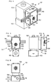
- the device 101 according to the invention shown in FIGS. 6 to 9 has a valve 102 with an electromagnetic actuator 103, in the actuator housing 104 of which an electrical coil (not shown here) and an electromagnetically displaceable armature can be provided.
- a coupling part 105 can be arranged on one side of the actuator 103, which can be inserted into a recess in the actuator housing 104 and can have contacts for the wire ends of the electrical coil and preferably three projecting flat rectangular contact tongues.
- a housing 106 preferably made of plastic, can be plugged onto the coupling part 105, which is essentially rectangular in shape and can have a rear wall 107, two side walls 108, 109, a base 110, an upper wall 111 and a detachable cover wall 112 forming the front housing wall, closes a housing opening 113 on the front side of the housing 106 remote from the actuator 103.
- the housing 106 can be detachably fastened to the coupling part 105 by means of a screw 114 which engages in a nut thread of the coupling part 105 and whose head 115 is expediently sunk in a recess 116 in the cover wall 112.
- a control line 118 can be inserted into these recesses 117 for a Single-wire bus system can be designed as a single-wire or for a multi-wire bus system, for example three-wire, preferably as a flat conductor cable.
- the recess 117 can be designed such that its width is approximately equal to the width of the flat conductor cable.
- troughs 119 can be formed, in which the convex curves of the control line 118 engage in a form-fitting manner.
- At least one preferably rectangular projection 120 which engages in the recess 117, can be formed on the detachable cover wall 112 on opposite sides.
- an adjusting part 121 can be provided on the upper wall 111 of the housing 106, by means of which an addressing switch 140 (FIG. 12) mounted in the housing 106 can be set from the outside without the cover wall 112 must be removed.
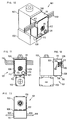
- FIG. 10 to 17 illustrated embodiment differs from the previously described example of FIG. 6 to 9 essentially in that no distance-forming coupling part 105 is provided between the actuator 103 and the housing 106. Rather, the housing 106 rests directly against the actuator 103 in a space-saving manner, so that a compact structural unit is provided.
- the housing 106 can be integrated directly on the actuator housing 104 and releasably connected to it. This can the housing 106 on the rear wall 107 has one or more retaining webs 122 which can be pushed into a recess 123 in the actuator housing 104 and which engage behind the wall of the actuator housing 104 (FIG. 9).
- the setting part 121 for the addressing switch 140 in this case is not provided on the upper wall 111, but on the removable cover wall 112, so that the addressing switch 140 can be set from the front.
- FIG. 11 and 12 it may be advantageous for the use of a plurality of single-core control lines 118 to form the recess 117 from, for example, three narrow slots, so that a single conductor can be inserted into each of the slots.
- a trough 119 can be formed for receiving the convex rounding of the control line 118.
- three web-shaped narrow projections 120 can be formed on opposite sides, which engage in the slot-shaped recesses 117.
- each attachment 120 facing the control line 118 can be favorable to also provide the end face of each attachment 120 facing the control line 118 with such a depression 119, in which the convex rounding of the control line 118 engages in a form-fitting manner, so that overall a safe cold and thicker for each individual bus line 118 Housing closure is guaranteed.
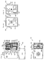
- FIG. 14 to 17 it can be seen that preferably three through connections 124, 125, 126 can be provided in the housing 106.
- a conductor of the control line 118 can be electrically contacted at each of the through connections 124, 125, 126.
- the through connections 124, 125, 126 which are preferably mounted in the upper part of the housing 106 above the screw 114, in the longitudinal direction of the control line 118 and laterally offset from one another.
- Each of the through connections 124, 125, 126 can be essentially U-shaped and have a contact slot 127 which is delimited by two knife contacts 128, 129 lying opposite one another. At the free end of the contact slot 127, an insertion opening 130 can be formed, which is delimited by two insertion bevels formed on the knife contacts 128, 129.
- To connect the control line 118 the respective conductor is pressed through the insertion opening 130 into the contact slot 127. The insulation of the conductor is cut by the knife contacts 128, 129 to such an extent that the latter make contact with the electrical conductor.
- the control line 118 is therefore not cut through, but is continuously contacted with the through connections 124, 125, 126 without interruption.
- a printed circuit board 131 can be provided in the housing 106, which is expediently mounted at a distance parallel to the plane of the rear wall 107 and adjoins the side walls 108, 109 as well as the bottom 110 and the top wall 111.
- a pin 132 can be formed on the rear wall 107 and a counter pin 133 on the cover wall 112, between which the circuit board 131 is held.
- the through connections 124, 125, 126 can preferably be fastened to the printed circuit board 131 in such a way that the insertion opening 130 of the contact slot 127 faces the housing opening 113 or the cover wall 112 and in the plane of the recesses formed in the side walls 108, 109 117 or slots.
- At least one contact 134 for a connection 135 of the electrical coil 136 of the actuator 103 can also be arranged on the printed circuit board 131 and a magnetic closure disk 137 of the actuator 103 can also be fastened at the bottom on the bottom 110 of the housing 106 by means of a contact screw 138. Furthermore, it can be favorable for the system controller to provide an integrated circuit 139 and the addressing switch 140 on the printed circuit board 131, which are expediently mounted in the lower part of the housing 106.
- FIG. 14 shows that the screw 114 penetrates the counter pin 133 formed on the cover wall 112 in a bore and that the free end of the screw 114 engages in a nut thread formed in the rear wall 107 or in the pin 132.
- the housing opening 113 is sealed off by the cover wall 112, the latter coming to bear against projections 141 of the housing 106.
- the device 201 according to the invention shown in FIG. 18 has an essentially rectangular distributor 202 with preferably eight solenoid valves 203, which are preferably arranged in a row next to one another on the front of the distributor 202 in such a way that a space-saving, compact compact module 204 is formed.
- a multiplicity of media-carrying channels can be located in the distributor 202, to which line connections 205 arranged on the upper end face of the distributor 202 in the drawing can be assigned.
- the line connections 205 are used for connection to hose or piping, not shown here, in which the medium, for example air, is guided.
- the valve body 206 of the solenoid valves 203 can preferably be on a web-shaped projection 207 projecting from the front of the distributor 202 can be releasably attached and connected to the channels of the distributor 202.
- a contact rail 208 extending parallel to the projection 207 can be provided on the front side of the distributor 202, which has a contact web 209 which is arranged on one long side 210 of the distributor 202 and projects beyond this on the rear side opposite the front side.
- the actuator 211 which is preferably designed as an electromagnetic head and is connected to the valve body 206, can be plugged onto this contact rail 208, so that electrical contact is made for a bus control.
- an integrated circuit 212 and an addressing switch 213, which can preferably be mounted on or within the contact rail 208 and enable the solenoid valves 203 to be controlled individually via the bus system.
- device connectors 214 can be provided for the connection of sensors, which are assigned to the solenoid valves 203 and can be arranged on the front of the distributor 202 on the side opposite the contact rail 208 on a rail 215 lying parallel next to the projection 207.
- the compact module 204 can be fastened with the rear side of the distributor 202 to a mounting rail 216, which can preferably have an approximately hat-shaped cross section.
- a three-wire bus control line 217 can be stored protected within the mounting rail 216, which preferably runs continuously without interruption near the base wall 218 of the mounting rail 216 and can preferably be arranged on a support wall 219 lying parallel to the base wall 218.
- through connections 220 can be arranged, which can be contacted without interruption with the control line 217, in such a way that when the distributor 202 is attached or plugged onto the opening side of the mounting rail 216 opposite the base wall 218, that is, without any special manipulation, the through-connection 220 is contacted with the control line 217, for example by two contact blades of the U-shaped through-connection 220 encompassing the wire of the control line 217.
- the contacting thus also takes place within the hat-shaped profile of the mounting rail 216, so that overall a quick assembly of several solenoid valves 203 combined to form the compact compact module 204 and reliable contacting of the bus control system is provided.
Landscapes
- Magnetically Actuated Valves (AREA)
- Connector Housings Or Holding Contact Members (AREA)
- Multi-Conductor Connections (AREA)
- Connections By Means Of Piercing Elements, Nuts, Or Screws (AREA)
Applications Claiming Priority (6)
| Application Number | Priority Date | Filing Date | Title |
|---|---|---|---|
| DE4305544A DE4305544C2 (de) | 1993-02-24 | 1993-02-24 | Einrichtung für einen Aktor |
| DE4305544 | 1993-02-24 | ||
| DE4400476A DE4400476C2 (de) | 1993-02-24 | 1994-01-11 | Einrichtung für einen Aktor |
| DE4400476 | 1994-01-11 | ||
| DE4401202A DE4401202A1 (de) | 1993-02-24 | 1994-01-18 | Einrichtung für einen Aktor |
| DE4401202 | 1994-01-18 |
Publications (2)
| Publication Number | Publication Date |
|---|---|
| EP0613210A2 true EP0613210A2 (fr) | 1994-08-31 |
| EP0613210A3 EP0613210A3 (fr) | 1996-02-21 |
Family
ID=27204797
Family Applications (1)
| Application Number | Title | Priority Date | Filing Date |
|---|---|---|---|
| EP94101965A Withdrawn EP0613210A3 (fr) | 1993-02-24 | 1994-02-09 | Installation pour un actionneur. |
Country Status (3)
| Country | Link |
|---|---|
| US (2) | US5453022A (fr) |
| EP (1) | EP0613210A3 (fr) |
| JP (1) | JPH0773910A (fr) |
Cited By (3)
| Publication number | Priority date | Publication date | Assignee | Title |
|---|---|---|---|---|
| DE202009007530U1 (de) * | 2009-02-16 | 2010-07-15 | Weidmüller Interface GmbH & Co. KG | Steckbare Anschlussvorrichtung zum Anschluss eines Kabels an ein Anschlussgehäuse |
| WO2012104370A1 (fr) * | 2011-02-02 | 2012-08-09 | Interroll Holding Ag | Dispositif de transport commandé de façon décentralisée à communication par bus |
| WO2014086389A1 (fr) * | 2012-12-03 | 2014-06-12 | Siemens Aktiengesellschaft | Module, en particulier pour des appareils de transmission de commande et de signalisation |
Families Citing this family (24)
| Publication number | Priority date | Publication date | Assignee | Title |
|---|---|---|---|---|
| US5704801A (en) * | 1996-08-30 | 1998-01-06 | The Whitaker Corporation | Power cable tap connector |
| FI101755B (fi) * | 1996-11-28 | 1998-08-14 | Nordic Aluminium Oyj | Sovitelma kosketinkiskojärjestelmän virranottimen yhteydessä |
| DE29701828U1 (de) * | 1997-02-03 | 1997-04-10 | Siemens AG, 80333 München | Modul zum Anschluß eines Aktuators oder Sensors |
| US6083035A (en) * | 1997-04-10 | 2000-07-04 | The Whitaker Corporation | Power cable tap connector with cable-sealing gaskets |
| US6022240A (en) * | 1997-04-10 | 2000-02-08 | The Whitaker Corporation | Power cable tap connector |
| AUPO947297A0 (en) * | 1997-09-26 | 1997-10-23 | Mannesmann Dematic Colby Pty Limited | Paperless picking systems |
| USD410627S (en) | 1997-11-07 | 1999-06-08 | Allen-Bradley Company, Llc | Cable connector interface |
| USD409144S (en) * | 1997-11-07 | 1999-05-04 | Allen-Bradley Company, Llc | Network cable connector |
| US6232557B1 (en) | 1997-11-07 | 2001-05-15 | Rockwell Technologies, Llc | Network cable and modular connection for such a cable |
| US6179644B1 (en) | 1997-11-07 | 2001-01-30 | Rockwell Technologies, Llc | Power and data network system media architecture |
| USD413099S (en) | 1997-11-07 | 1999-08-24 | Allen-Bradley Company, Llc | Modular connector |
| US6039596A (en) * | 1997-11-10 | 2000-03-21 | The Whitaker Corporation | Gaskets for power cable tap connector |
| JPH11204155A (ja) * | 1998-01-09 | 1999-07-30 | Sumitomo Wiring Syst Ltd | ワイヤハーネスと電気接続箱の接続構造 |
| JPH11204170A (ja) * | 1998-01-12 | 1999-07-30 | Sumitomo Wiring Syst Ltd | ワイヤハーネスと電気接続箱の接続構造 |
| JP3275827B2 (ja) * | 1998-03-26 | 2002-04-22 | 住友電装株式会社 | ワイヤハーネスと電気接続箱の接続方法 |
| JPH11273813A (ja) * | 1998-03-26 | 1999-10-08 | Sumitomo Wiring Syst Ltd | ワイヤハーネスと電気接続箱の接続構造 |
| US6095867A (en) * | 1998-09-21 | 2000-08-01 | Rockwell Technologies, Llc | Method and apparatus for transmitting power and data signals via a network connector system including integral power capacitors |
| US6102731A (en) * | 1998-12-21 | 2000-08-15 | Lucent Technologies Inc. | Connector security mechanism |
| DE29905589U1 (de) * | 1999-03-26 | 1999-06-10 | Hans Bernstein GmbH & Co., 32457 Porta Westfalica | Schalter |
| EP1131860B1 (fr) | 1999-09-20 | 2008-05-28 | Woertz Ag | Dispositif de mise en contact pour cable plat |
| JP4346592B2 (ja) * | 2005-03-09 | 2009-10-21 | 古河電気工業株式会社 | 通信制御ic内蔵コネクタ及び通信制御ic内蔵コネクタ付き配線体 |
| US7134905B1 (en) * | 2005-03-31 | 2006-11-14 | Yazaki North America, Inc. | Connection system with electronic circuit board |
| EP2456010A1 (fr) * | 2010-11-23 | 2012-05-23 | Saia-Burgess Controls AG | Composant de réseau comprenant un dispositif électrique |
| US8858255B2 (en) * | 2013-03-08 | 2014-10-14 | Hubbell Incorporated | Magnetic screw guide for distribution block assembly |
Family Cites Families (12)
| Publication number | Priority date | Publication date | Assignee | Title |
|---|---|---|---|---|
| US4002397A (en) * | 1975-09-29 | 1977-01-11 | Wolsk Associates, Ltd. | Connector for electric plug |
| US4286835A (en) * | 1980-07-22 | 1981-09-01 | Northern Telecom Inc. | Modular telephone connector |
| US4508399A (en) * | 1984-01-03 | 1985-04-02 | Amp Incorporated | Polarized ribbon cable connector having circuit components therein |
| US4743080A (en) * | 1986-09-25 | 1988-05-10 | G & H Technology, Inc. | Flat cable connector |
| US4744774A (en) * | 1987-01-20 | 1988-05-17 | Amp Incorporated | Electrical connector having conductive sheath-clamping means |
| US4932873A (en) * | 1989-02-06 | 1990-06-12 | Amphenol Interconnect Products Corporation | Terminator assembly |
| DE3933942A1 (de) * | 1989-10-11 | 1991-04-18 | Pfaff Ag G M | Einrichtung zum elektrischen verbinden von mindestens einem verbraucher und einem mehradrigen kabel |
| DE476322T1 (de) * | 1990-09-10 | 1992-07-02 | Yokogawa Electric Corp., Musashino, Tokio/Tokyo | Gehaeusenanordnung fuer eine elektronische anlage. |
| DE9113231U1 (de) * | 1990-10-29 | 1992-03-19 | Klöckner-Moeller GmbH, 5300 Bonn | Kontaktanschlußverbinder für mehradrige Flachbandleitungen |
| US5092788A (en) * | 1990-12-03 | 1992-03-03 | Motorola, Inc. | Self-contained universal accessory connector and seal |
| US5428288A (en) * | 1991-04-29 | 1995-06-27 | Trw Inc. | Microelectric monitoring device |
| US5125846A (en) * | 1991-07-25 | 1992-06-30 | Molex Incorporated | Input-output electrical connector |
-
1994
- 1994-02-09 EP EP94101965A patent/EP0613210A3/fr not_active Withdrawn
- 1994-02-24 JP JP6026885A patent/JPH0773910A/ja active Pending
- 1994-02-24 US US08/201,363 patent/US5453022A/en not_active Expired - Fee Related
- 1994-07-15 US US08/275,498 patent/US5501611A/en not_active Expired - Fee Related
Cited By (4)
| Publication number | Priority date | Publication date | Assignee | Title |
|---|---|---|---|---|
| DE202009007530U1 (de) * | 2009-02-16 | 2010-07-15 | Weidmüller Interface GmbH & Co. KG | Steckbare Anschlussvorrichtung zum Anschluss eines Kabels an ein Anschlussgehäuse |
| WO2012104370A1 (fr) * | 2011-02-02 | 2012-08-09 | Interroll Holding Ag | Dispositif de transport commandé de façon décentralisée à communication par bus |
| EP2671288B1 (fr) | 2011-02-02 | 2016-08-31 | Interroll Holding AG | Dispositif de transport commandé de façon décentralisée à communication par bus |
| WO2014086389A1 (fr) * | 2012-12-03 | 2014-06-12 | Siemens Aktiengesellschaft | Module, en particulier pour des appareils de transmission de commande et de signalisation |
Also Published As
| Publication number | Publication date |
|---|---|
| EP0613210A3 (fr) | 1996-02-21 |
| US5501611A (en) | 1996-03-26 |
| US5453022A (en) | 1995-09-26 |
| JPH0773910A (ja) | 1995-03-17 |
Similar Documents
| Publication | Publication Date | Title |
|---|---|---|
| DE3807645C2 (de) | Steckverbindungssystem für elektrische Leiter | |
| DE3215054A1 (de) | System zur verteilung von pneumatischen steuersignalen auf elektrischem weg | |
| DE3614592C1 (de) | Anschlussleiste fuer Kabeladern,insbesondere von Fernsprechkabeln | |
| DE19612575C2 (de) | Vorrichtung zur lösbaren Befestigung von Geräten und zu deren elektrischem Anschließen | |
| DE69112304T2 (de) | Gehäuse für elektrische Niederspannungsgeräte. | |
| DE4217913A1 (de) | Kombinierte kabelschuh- und verbindungsanordnung fuer einen elektrischen schalter | |
| DE3233255C2 (de) | Elektrische Anschlußklemme, insbesondere Schaltanlagen-Reihenklemme | |
| DE4400476C2 (de) | Einrichtung für einen Aktor | |
| DE10236398B3 (de) | Anschlusssystem | |
| DE19846576C2 (de) | Plombierbare Verschließeinrichtung | |
| DE10256374B3 (de) | Kontakteinsatz zum Anschließen der Leiter eines mehradrigen Kabels und Sensor-Aktor-Verteiler | |
| DE19903030C1 (de) | Vorrichtung zur abisolierfreien Kontaktierung eines Flachkabels | |
| DE10205470C1 (de) | Anschlusskontakt | |
| DE19530947C2 (de) | Klemmblock für Elektrizitätszähler | |
| DE19500436A1 (de) | Elektrische Steckverbindungseinrichtung | |
| EP0760539A2 (fr) | Barrette à borne avec barre omnibus | |
| DE102008014180B4 (de) | Trennklemme, insbesondere Neutralleiter-Trennklemme | |
| DE3150438A1 (de) | Gehaeuse zur aufnahme der zur beschaltung einer magnetspule eines hydraulikventils oder dgl. erforderlichen elektrischen bauteile | |
| EP0537790B1 (fr) | Connecteur pour câble-ruban plat | |
| DE69607136T2 (de) | Schalttafel und Anschlusseinrichtung für elektrische Installationen mit modularen Einrichtungen | |
| DE19513645C2 (de) | Klemmenanordnung | |
| DE2712723A1 (de) | Elektrischer verteiler | |
| DE2448111B2 (de) | Anordnung zum anschluss elektrischer leitungen an ein elektrisches geraet | |
| DE9400326U1 (de) | Einrichtung für einen Aktor | |
| DE9302630U1 (de) | Einrichtung für einen Aktor |
Legal Events
| Date | Code | Title | Description |
|---|---|---|---|
| PUAI | Public reference made under article 153(3) epc to a published international application that has entered the european phase |
Free format text: ORIGINAL CODE: 0009012 |
|
| 17P | Request for examination filed |
Effective date: 19940209 |
|
| AK | Designated contracting states |
Kind code of ref document: A2 Designated state(s): AT BE CH DE FR GB IT LI NL SE |
|
| PUAL | Search report despatched |
Free format text: ORIGINAL CODE: 0009013 |
|
| AK | Designated contracting states |
Kind code of ref document: A3 Designated state(s): AT BE CH DE FR GB IT LI NL SE |
|
| STAA | Information on the status of an ep patent application or granted ep patent |
Free format text: STATUS: THE APPLICATION IS DEEMED TO BE WITHDRAWN |
|
| 18D | Application deemed to be withdrawn |
Effective date: 19960822 |