EP0613534B1 - Ensemble soupape de regulation de debit et procede destine a equilibrer des debits - Google Patents
Ensemble soupape de regulation de debit et procede destine a equilibrer des debits Download PDFInfo
- Publication number
- EP0613534B1 EP0613534B1 EP92924977A EP92924977A EP0613534B1 EP 0613534 B1 EP0613534 B1 EP 0613534B1 EP 92924977 A EP92924977 A EP 92924977A EP 92924977 A EP92924977 A EP 92924977A EP 0613534 B1 EP0613534 B1 EP 0613534B1
- Authority
- EP
- European Patent Office
- Prior art keywords
- flow
- flow control
- balancing
- control valve
- hydraulic motors
- Prior art date
- Legal status (The legal status is an assumption and is not a legal conclusion. Google has not performed a legal analysis and makes no representation as to the accuracy of the status listed.)
- Expired - Lifetime
Links
- 238000000034 method Methods 0.000 title claims abstract description 12
- 239000012530 fluid Substances 0.000 claims abstract description 22
- 230000005540 biological transmission Effects 0.000 claims abstract description 15
- 230000002706 hydrostatic effect Effects 0.000 claims abstract description 13
- 230000001419 dependent effect Effects 0.000 claims abstract description 10
- 238000006073 displacement reaction Methods 0.000 claims abstract description 6
- 230000033228 biological regulation Effects 0.000 claims description 9
- 238000011144 upstream manufacturing Methods 0.000 claims description 9
- 238000004891 communication Methods 0.000 claims description 3
- 238000001514 detection method Methods 0.000 claims 4
- 230000001276 controlling effect Effects 0.000 description 6
- 238000011161 development Methods 0.000 description 2
- 230000018109 developmental process Effects 0.000 description 2
- 238000010586 diagram Methods 0.000 description 2
- 238000009434 installation Methods 0.000 description 2
- 230000001105 regulatory effect Effects 0.000 description 2
- 230000035945 sensitivity Effects 0.000 description 2
- 230000000712 assembly Effects 0.000 description 1
- 238000000429 assembly Methods 0.000 description 1
- 230000001427 coherent effect Effects 0.000 description 1
- 238000002485 combustion reaction Methods 0.000 description 1
- 230000003247 decreasing effect Effects 0.000 description 1
- 230000000694 effects Effects 0.000 description 1
- 230000002349 favourable effect Effects 0.000 description 1
- 238000004519 manufacturing process Methods 0.000 description 1
- 230000002441 reversible effect Effects 0.000 description 1
- 239000013589 supplement Substances 0.000 description 1
Images


Classifications
-
- F—MECHANICAL ENGINEERING; LIGHTING; HEATING; WEAPONS; BLASTING
- F16—ENGINEERING ELEMENTS AND UNITS; GENERAL MEASURES FOR PRODUCING AND MAINTAINING EFFECTIVE FUNCTIONING OF MACHINES OR INSTALLATIONS; THERMAL INSULATION IN GENERAL
- F16H—GEARING
- F16H61/00—Control functions within control units of change-speed- or reversing-gearings for conveying rotary motion ; Control of exclusively fluid gearing, friction gearing, gearings with endless flexible members or other particular types of gearing
- F16H61/38—Control of exclusively fluid gearing
- F16H61/40—Control of exclusively fluid gearing hydrostatic
- F16H61/44—Control of exclusively fluid gearing hydrostatic with more than one pump or motor in operation
- F16H61/456—Control of the balance of torque or speed between pumps or motors
-
- F—MECHANICAL ENGINEERING; LIGHTING; HEATING; WEAPONS; BLASTING
- F15—FLUID-PRESSURE ACTUATORS; HYDRAULICS OR PNEUMATICS IN GENERAL
- F15B—SYSTEMS ACTING BY MEANS OF FLUIDS IN GENERAL; FLUID-PRESSURE ACTUATORS, e.g. SERVOMOTORS; DETAILS OF FLUID-PRESSURE SYSTEMS, NOT OTHERWISE PROVIDED FOR
- F15B13/00—Details of servomotor systems ; Valves for servomotor systems
- F15B13/02—Fluid distribution or supply devices characterised by their adaptation to the control of servomotors
- F15B13/022—Flow-dividers; Priority valves
-
- F—MECHANICAL ENGINEERING; LIGHTING; HEATING; WEAPONS; BLASTING
- F16—ENGINEERING ELEMENTS AND UNITS; GENERAL MEASURES FOR PRODUCING AND MAINTAINING EFFECTIVE FUNCTIONING OF MACHINES OR INSTALLATIONS; THERMAL INSULATION IN GENERAL
- F16H—GEARING
- F16H61/00—Control functions within control units of change-speed- or reversing-gearings for conveying rotary motion ; Control of exclusively fluid gearing, friction gearing, gearings with endless flexible members or other particular types of gearing
- F16H61/38—Control of exclusively fluid gearing
- F16H61/40—Control of exclusively fluid gearing hydrostatic
-
- F—MECHANICAL ENGINEERING; LIGHTING; HEATING; WEAPONS; BLASTING
- F16—ENGINEERING ELEMENTS AND UNITS; GENERAL MEASURES FOR PRODUCING AND MAINTAINING EFFECTIVE FUNCTIONING OF MACHINES OR INSTALLATIONS; THERMAL INSULATION IN GENERAL
- F16H—GEARING
- F16H61/00—Control functions within control units of change-speed- or reversing-gearings for conveying rotary motion ; Control of exclusively fluid gearing, friction gearing, gearings with endless flexible members or other particular types of gearing
- F16H61/38—Control of exclusively fluid gearing
- F16H61/40—Control of exclusively fluid gearing hydrostatic
- F16H61/4035—Control of circuit flow
-
- Y—GENERAL TAGGING OF NEW TECHNOLOGICAL DEVELOPMENTS; GENERAL TAGGING OF CROSS-SECTIONAL TECHNOLOGIES SPANNING OVER SEVERAL SECTIONS OF THE IPC; TECHNICAL SUBJECTS COVERED BY FORMER USPC CROSS-REFERENCE ART COLLECTIONS [XRACs] AND DIGESTS
- Y10—TECHNICAL SUBJECTS COVERED BY FORMER USPC
- Y10T—TECHNICAL SUBJECTS COVERED BY FORMER US CLASSIFICATION
- Y10T137/00—Fluid handling
- Y10T137/2496—Self-proportioning or correlating systems
- Y10T137/2559—Self-controlled branched flow systems
- Y10T137/2564—Plural inflows
Definitions
- the invention generally relates to hydrostatic transmissions and more specifically relates to a method and a flow control valve assembly for achieving mutual balancing of flows through consumers or working apparatuses in hydrostatic transmissions, of the kind indicated in the preambles of claims 1 and 5 respectively.
- Hydrostatic transmissions of the kind indicated in the introduction are especially employed for propelling special vehicles, such as cross-country vehicles and other slow moving vehicles, whereby the drive motor, for instance a combustion engine or an electric motor, of the vehicle is employed for driving one or more hydraulic pumps which usually are of the kind having a variable displacement.
- the flow from the hydraulic pump/pumps drive hydraulic motors which directly or through a gear-box drives wheels or (caterpillar) tracks of the vehicle.
- a favourable operation may however be achieved by employing proportionally controlled valves which are provided one for each hydraulic motor and which are controlled by an advanced electronic control system employing sensors on each wheel/track.
- proportionally controlled valves which are provided one for each hydraulic motor and which are controlled by an advanced electronic control system employing sensors on each wheel/track.
- the basic object of the invention is to provide a method and a flow control valve assembly of the kind indicated in the introduction, by means of which an automatic balancing of the flows through the different hydraulic motors is performed for obtaining an optimum tractive force for the wheels or tracks being driven by the hydraulic motors, and this also when differences occur in the grip of the wheels or tracks against the ground surface.
- a sufficient difference in rotational speed for the wheels or tracks is permitted, in order to allow for for instance turning of a vehicle with maximum steering angle without any wheel or track slipping or skidding, whereby no engagement or disengagement shall be required, independent of the driving conditions.
- the basic object is achieved by means of a method and a flow control valve assembly of the kind indicated in the characterizing portions of the enclosed patent claims 1 and 5 respectively.
- Said hydrostatic transmission comprises a hydraulic pump P, preferably having a variable displacement and a reversible direction of flow, the hydraulic pump P being driven by the not illustrated engine of the vehicle and in turn feeding hydraulic fluid to four hydraulic motors M1-M4 connected in parallel and in turn driving their own wheel or track (not illustrated) for propelling the vehicle.
- Figs. 1-7 illustrate a first embodiment of the invention where the flow through the hydraulic motors is controlled by means of a flow control valve assembly 10 in the shape of a "flow combiner".
- the flow through the hydraulic motors M1-M4 is controlled by means of a controlling downstream thereof
- Fig. 1 illustrates a case where controlling is performed only in one direction, i.e. by controlling the flow from the motors M1-M4 by means of a flow control valve assembly 10 provided at their outlet side with respect to the normal direction of feed of the pump P for driving the vehicle forwardly, i.e. the case when flow control or balancing is mostly desired
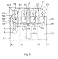
- the explanatory diagram in Fig. 1 also applies to a "flow divider" 110 according to Fig. 8
- Fig. 6 illustrates an example where two "flow combiners" are employed in the case when regulation is desired in both directions (in this case the explanatory diagram likewise applies also to two "flow dividers").
- Figs. 2-5 the regulation of the flow of hydraulic fluid from the respective hydraulic motors M1-M4 is carried out by means of individual, but functionally cooperating flow control valves 1, 2, 3 and 4 respectively in the flow control valve assembly 10, said flow control valves 1-4 receiving the flow from the respective hydraulic motors M1-M4.
- the valves could theoretically be provided as separate valves it is advantageous to provide the flow control valves 1-4 in a common housing 11, as will be most clearly seen in connection with the embodiment of Figs. 7a and 7b, in order to obtain an optimum design and a maximum reduction of the requirement of space, of the installation work and of the productions costs.
- the flow control valves 1-4 are identical, and therefore their design will only be described with reference to the valve 1 in Fig. 2.
- the flow control valve 1 comprises a slide or spool 6 movable in a bore 5, having an active or work area A1 and being adapted to cooperate with a seat 8 in the bore 5 with a portion 6a thereof, in order to thereby control a restriction or throttle between the spool portion 6a and the seat 8.
- the spool 6 is, at one end 6b thereof, biased by means of a spring 9 having a spring force F1.
- the spool is biased in a direction for displacing the spool portion 6a away from the seat 8, in order to thereby open the restriction therebetween.
- the spool 6 In the region of the opening or orifice of the inlet bore 12 leading into the bore 5, the spool 6 is provided with a portion 6c having a reduced diameter and serving to permit fluid to flow from the inlet bore 12 into the bore 5 and past the spool portion 6a and the seat 8, in the open position of the valve 1.
- the spool 6 is also provided with a stop means 6d for restricting the movement of the spool in the opening-direction, as is indicated in Fig. 2.
- the flow control valve 1 also comprises a check valve 7 for reversing the flow without regulation or balancing, when the flow direction of the pump P is reversed.
- the invention is not restricted to the provision of the check valve 7 in the spool 6, and the check valve may with the same advantage be positioned outside the actual flow control valve or may theoretically also be provided outside the flow control valve assembly 10.
- the bore 5 of the flow control valve 1 is in direct (Figs. 2-5) or indirect (Fig. 7b) communication with a balancing chamber 13 (see especially Fig. 7b) in which a balancing piston 17 is displaceable, being guided (the piston rod 14a) in the housing 11.
- the connection between the flow control valves 1-4 and the balancing chamber 13 opens in the upper wall of the chamber 13, at seats 15.
- Upper surfaces of the balancing piston 14 cooperate with the seats 15 for forming a restriction therebetween which is variable dependent on the flow, and for thereby providing different pressure drops across the seats 15 when the balancing function is performed.
- balancing channels 18 lead to the spring side of the spools 6, on the one hand for leading the flow to the motors through the check valves 7, past the control and balancing means when the pump P is reversed, and most of all for applying the system pressure p to this side of the spools 6.
- a balancing or equalization of the system pressure occurs on the opposite side of the spools 6 so that only the pressure increase upstream of the seats 15, generated by a pressure drop produced thereacross during the balancing function (described more closely below) acts to overcome the force F1 of the spring 9.
- the spool 6 also has an active area A1 at the spring side.
- Fig. 2 illustrates the condition of the flow control valve assembly 10 when the pump P is not in operation, i.e. when no flow takes place through the valve assembly 10.
- all flow control valves 1-4 are moved to the completely open end position, determined by the stop means 6d at the spool 6, through the force of the springs 9; and the balancing piston 14 is biased to sealingly engage all of the seats 15 through the force of the spring 16, i.e.
- Fig. 3 illustrates the condition of the valve assembly 10 when hydraulic fluid from the pump P is fed through the hydraulic motors M1-M4 and to the valve assembly 10 and when the flows are equal or substantially equal through all of the hydraulic motors M1-M4, i.e. when the wheels or tracks are rotating with substantially the same speed, i.e. have the same grip against the surface.
- Hydraulic fluid from the respective motors M1-M4 now flows through the respective channel 12 and into the respective flow control valve 1-4, whereby the hydraulic fluid in the respective flow control valve 1-4 flows into the bore 5 externally of the spool 6, past the seat 8 and the spool portion 6a and to the seat 15.
- the balancing piston 14 In order for hydraulic fluid to be able to flow past the seats 15 and further out through the channels 17 and back to the pump P, the balancing piston 14 has to be displaced against the spring 16 by the combined force of the hydraulic fluid flowing through all of the flow control valves 1-4.
- the hydraulic pressure behind the seat 15 is equal to the pressure on the spring side of the spool 6, i.e. the system pressure p, since the channels 17 communicate with the bores 5 on the spring side of the spools 6 through the balancing channels 18.
- the pressure increase ⁇ p established upstream of the seat 15 multiplied with the area A1 of the spool 6 (equal to the area of the seat 8) gives rise to a force F3 acting against the spool 6 and tending to displace the same against the spring 9.
- the force F1 is slightly greater than or equal to the force F3 when the flow through the different valves 1-4 is substantially equal.
- Fig. 4 illustrates the flow control valve assembly 10 in the condition when the flow has descreased through any or some of the hydraulic motors M1-M4, and more specifically, in the illustrated case, when the flow through the motors M1 and M2 and accordingly through the control valves 1 and 2 is too small or is missing altogether.
- this advantageous operation is achieved by the fact that for all flow control valves 1-4 the outlet restrictions between the seat 15 and the balancing piston 14 are automatically and mutually adjusted to different, mutually equal sizes depending on one hand upon differences in flow through the separate motors, and thereby through the flow control valves, and on the other hand upon differences in the total flow through the transmission.
- Fig. 5 illustrates the flow control valve assembly 10 in its condition when the direction of flow of the hydraulic pump P is reversed, whereby hydraulic fluid from the pump P flows through the flow control valves 1-4 and to the hydraulic motors M1-M4, through the check valves 7.
- Figs. 7a and 7b illustrate a suggested practical embodiment of the flow control valve assembly according to the invention, but it should be emphasized that this is only an example of a possible embodiment and that the valve assembly may, within the scope of the invention, be modified in many ways obvious to a man skilled in the art, within the scope of the enclosed patent claims and for achieving the operation at which the invention is aiming.
- Figs. 7a and 7b the components of the valve assembly 10 have been provided with the same reference numerals as in Figs. 2-5, and only some practical differences are to be explained here.
- the flow control valves 1-4 are in Figs. 2-5 illustrated in a row side by side, it is preferable in the practical embodiment, at least in the case with four flow control valves 1-4, to provide these distributed with their centres on a circle having its centre in the central axis (Fig. 7a) of the housing 11.
- the bore 5 of the flow control valves 1-4 is furthermore not communicating directly with the balancing chamber 15 but through an outlet bore 5a which is connected thereto, which is parallel to the bore 5 and in which a bushing is inserted which forms the seat 15, as is illustrated in Fig. 7b.
- the balancing piston 14 is provided upside-down in the housing 11 as compared to the embodiment of Figs. 2-5, with the piston rod facing upwardly and receiving the spring 16 being provided with one of its ends supported on the upper end of the piston rod and with its other end supported on the bottom of the balancing chamber 13, whereby the flow control valve assembly 10 may be built even more compact, i.e. significantly shorter in the direction of movement of the spools 6 and of the piston 14.
- the outlet of the balancing chamber 13 to the pump connection i.e. corresponding to the bore 17 in the embodiment according to Figs. 2-5, is provided centrally through the housing 11, below the piston 14 in Fig. 7b. Due to the fact that the bore 5 does not communicate directly with the balancing chamber 13 in this embodiment, the stop means for restricting the downward movement of the spool 6 may in this case be formed by the bottom of the bore 5.
- FIG. 8 illustrates a basic design of a flow control valve assembly 110 in the shape of a "flow divider", according to the invention.
- the parts of a flow control valve assembly 110 corresponding to the parts of the flow control valve assembly 10 according to Figs. 2-5 have been given the same reference numerals plus 100.
- the flow control valve assembly 110 illustrated in Fig. 8 has the same basic design as the flow control valve assembly 10 according to Fig. 2, whereby the differences are that the balancing piston 114, through the spring 116, and the spool 106, through the spring 109, are biased in opposite directions as compared to the corresponding components in the flow control valve assembly 10, and in that the check valve 107 is reversed in order to conduct the flow from the motors M1-M4 to the pump P without balancing.
- the pressure drop established across the seats 115 gives rise to a decrease in pressure in the flow control valves 101-104, whereby, when the flow is substantially equal through the flow control valves, the springs 109 and 116 and the areas A1 and A2 are so dimensioned that the force of the spring 109 and the force of the hydraulic pressure acting on the same side of the spool 106 are sufficient to hold the spool 106 in a completely open position, counteracting the system pressure p at the opposite side of the spool 106.
- a flow combiner 10 and a flow divider 110 according to the invention may preferably be combined, in a not illustrated manner, in one and the same housing and in fluidum communication with each other.
- the check valves 7 and 107 become superfluous since the flow control valves take over their function, and moreover the number of spools may be reduced to half since the same spool is employed in the "flow divider" and in the "flow combiner". In this manner the system may be designed extremely compact.
Landscapes
- Engineering & Computer Science (AREA)
- General Engineering & Computer Science (AREA)
- Mechanical Engineering (AREA)
- Physics & Mathematics (AREA)
- Fluid Mechanics (AREA)
- Control Of Fluid Gearings (AREA)
- Servomotors (AREA)
Abstract
Claims (10)
- Procédé pour, dans une transmission hydrostatique, faire alimenter par une pompe hydraulique (P) de préférence à cylindrée variable , un certain nombre de moteurs hydrauliques (M1, M2, M3, M4) prévus en association avec des roues d'entraînement respectives, des chenilles d'entraînement ou des moyens d'entraînement correspondants, équilibrant mutuellement l'écoulement de fluide hydraulique à travers les différents moteurs hydrauliques (M1 à M4) en commandant individuellement l'écoulement vers et/ou en provenance de ceux-ci, caractérisé en ce que les écoulements individuels des fluides hydrauliques à travers les moteurs hydrauliques respectifs (M1 à M4) sont détectés et comparés par l'intermédiaire de rétrécissements respectifs (14, 15 ; 114, 115) qui sont variables en fonction de l'écoulement total mais qui sont de dimensions égales entre eux, et en ce que, pour une commande ou un équilibrage optimaux, les différences détectées dans l'écoulement à travers les différents moteurs hydrauliques sont elles-mêmes employées directement pour l'équilibrage.
- Procédé selon la revendication 1, caractérisé en ce que l'équilibrage des écoulements est accompli au moyen de vannes de commande d'écoulement individuelles (respectivement 1, 2, 3 et 4 ; respectivement 101, 102, 103 et 104) associées aux moteurs hydrauliques respectifs (M1 à M4) et en ce que la régulation des vannes de commande d'écoulement individuelles (1 à 4 ; 101 à 104) est automatiquement effectuée en fonction des différentes chutes de pression, correspondant aux différences détectées dans l'écoulement à travers les différents moteurs hydrauliques (M1 à M4), établies par l'intermédiaire des rétrécissements respectifs (14, 15 ; 114, 115).
- Procédé selon la revendication 2, rassemblant les écoulements en provenance des moteurs hydrauliques (M1 à M4) en aval de ceux-ci, caractérisé en ce que la détection de différences d'écoulement au travers des différents moteurs hydrauliques (M1 à M4) est effectuée au moyen de rétrécissements (14, 15) en relation avec les sorties des vannes de commande d'écoulement (1 à 4), ce par quoi, par des différences d'écoulement au travers des moteurs séparés (M1 à M4), l'augmentation en pression créée par la chute de pression en amont du rétrécissement ou des rétrécissements (14, 15) associés à un écoulement plus grand, est employée directement pour le réglage de la vanne de commande d'écoulement ou des vannes de commande d'écoulement (1 à 4) associées et par ce moyen, pour l'équilibrage des écoulements.
- Procédé selon la revendication 2, divisant les écoulements en provenance des moteurs hydrauliques (M1 à M4) en amont de ceux-ci, caractérisé en ce que la détection de différences dans l'écoulement au travers des différents moteurs hydrauliques (M1 à M4) est effectuée au moyens de rétrécissements (114, 115) en relation avec les entrées des vannes de commande d'écoulement (101 à 104), ce par quoi, par des différences d'écoulement au travers des moteurs séparés (M1 à M4), la diminution en pression créée par la chute de pression en aval du rétrécissement ou des rétrécissements (114, 115) associés à un écoulement plus grand est employée directement pour le réglage de commande de la vanne de commande d'écoulement ou des vannes de commande d'écoulement (101 à 104) associées et, par ce moyen, pour l'équilibrage des écoulements.
- Montage de vanne de commande d'écoulement destiné à être relié à une transmission hydrostatique ayant une pompe hydraulique (P) de préférence à cylindrée variable alimentant un certain nombre de moteurs hydrauliques (M1 à M4) prévus en association avec des roues d'entraînement respectives, des chenilles d'entraînement ou des moyens d'entraînement correspondants, ce par quoi le montage de commande d'écoulement (10 ; 110) comprend des moyens (1, 2, 3, 4 ; 101, 102, 103, 104) pour commander individuellement l'écoulement au travers des moteurs hydrauliques (M1 à M4) et pour équilibrer les écoulements, caractérisé en ce que le montage de vanne de commande d'écoulement (10 ; 110) comprend des moyens de détection (14, 15, 16 ; 114, 115, 116) sous la forme de rétrécissements (14, 15 ; 114, 115) qui sont variables en fonction de l'écoulement total mais qui sont de dimensions égales entre eux et qui sont destinés à détecter et à comparer l'écoulement du fluide hydraulique au travers des moteurs hydrauliques respectifs (M1 à M4), et qui comprend des vannes de commande d'écoulement (1 à 4 ; 101 à 104) qui en fonctionnement sont reliées aux moyens de détection d'écoulement (14, 15, 16 ; 114, 115, 116) pour le réglage de commande automatique des vannes de commande d'écoulement individuelles (1 à 4 ; 101 à 104) en fonction des différences d'écoulement au travers des différents moteurs hydrauliques (M1 à M4) détectées par les moyens de détection d'écoulement.
- Montage de vanne de commande d'écoulement selon la revendication 5, caractérisé en ce que les moyens de détection d'écoulement consistent en des sièges (15 ; 115) qui, dans un mode de réalisation en tant qu'assembleur d'écoulements (10), sont prévus en aval des vannes de commande d'écoulement respectives (1 à 4), ou en variante, dans un mode de réalisation en tant que diviseur d'écoulements, sont prévus en amont des vannes de commande d'écoulement respectives(101 à 104), et qui coopèrent avec un piston d'équilibrage (14 ; 114) commun à toutes les vannes de commande d'écoulement, repoussé dans une direction vers les sièges (15 ; 115) par un ressort (16 ; 116), et forment des rétrécissements qui sont d'égales dimensions pour toutes les vannes de commande d'écoulement (1 à 4 ; 101 à 104) et qui sont variables en fonction de l'écoulement total.
- Montage de vanne de commande d'écoulement selon la revendication 5 ou la revendication 6, caractérisé en ce que les vannes de commande d'écoulement (1 à 4 ; 101 à 104) comprennent des moyens de réglage de commande (8, 6 ; 108, 106) qui consistent en un tiroir (6 ; 106) déplaçable dans un alésage (5 ; 105) et coopérant avec un siège (8 ; 108) formé sur l'alésage, pour commander l'écoulement au travers des vannes de commande d'écoulement respectives (1 à 4 ; 101 à 104), en ce que le tiroir (6 ; 106) est repoussé au moyen d'un ressort (9 ; 109) dans une direction pour déplacer le tiroir dans une position correspondant à une vanne de commande d'écoulement entièrement ouverte et en ce que des canaux d'équilibrage (18 ; 118) sont prévus qui, dans un mode de réalisation en tant qu'assembleur d'écoulements (10), conduisent le fluide hydraulique en aval du piston d'équilibrage (14) vers le côté ressort des tiroirs (6) ou, en variante, dans un mode de réalisation en tant que diviseur d'écoulements (110), conduisent le fluide hydraulique en amont du piston d'équilibrage (114) vers le côté des tiroirs (106) opposé au ressort (109).
- Montage de vanne de commande d'écoulement selon l'une quelconque des revendications 5 à 7, caractérisé en ce que les vannes de commande d'écoulement (1 à 4 ; 101 à 104) sont prévues, ensemble avec les moyens de détection d'écoulement associés (14, 15, 16 ; 114, 115, 116), dans un compartiment commun (11 ; 111).
- Montage de vanne de commande d'écoulement selon l'une quelconque des revendications 5 à 8, caractérisé en ce que le montage de vanne de commande d'écoulement (10 ; 110) comprend des clapets anti-retour (7 ; 107) pour permettre un écoulement libre du fluide hydraulique au travers de celles-ci sans régulation, dans une direction opposée à une direction d'alimentation de la pompe (P) dans laquelle l'équilibrage est souhaité.
- Montage de vanne de commande d'écoulement selon l'une quelconque des revendications 5 à 9, caractérisé en ce qu'un diviseur d'écoulements (110) et un assembleur d'écoulements (10) sont prévus dans un seul et même compartiment, en communication de fluide l'un avec l'autre.
Applications Claiming Priority (3)
| Application Number | Priority Date | Filing Date | Title |
|---|---|---|---|
| SE9103553A SE469485B (sv) | 1991-11-29 | 1991-11-29 | Foerfarande och floedesregleringsventilaggregat foer floedesbalansering |
| SE9103553 | 1991-11-29 | ||
| PCT/SE1992/000811 WO1993011377A1 (fr) | 1991-11-29 | 1992-11-25 | Ensemble soupape de regulation de debit et procede destine a equilibrer des debits |
Publications (2)
| Publication Number | Publication Date |
|---|---|
| EP0613534A1 EP0613534A1 (fr) | 1994-09-07 |
| EP0613534B1 true EP0613534B1 (fr) | 1996-07-24 |
Family
ID=20384477
Family Applications (1)
| Application Number | Title | Priority Date | Filing Date |
|---|---|---|---|
| EP92924977A Expired - Lifetime EP0613534B1 (fr) | 1991-11-29 | 1992-11-25 | Ensemble soupape de regulation de debit et procede destine a equilibrer des debits |
Country Status (8)
| Country | Link |
|---|---|
| US (1) | US5435132A (fr) |
| EP (1) | EP0613534B1 (fr) |
| JP (1) | JPH07505204A (fr) |
| AU (1) | AU3099892A (fr) |
| DE (1) | DE69212496T2 (fr) |
| DK (1) | DK0613534T3 (fr) |
| SE (1) | SE469485B (fr) |
| WO (1) | WO1993011377A1 (fr) |
Families Citing this family (1)
| Publication number | Priority date | Publication date | Assignee | Title |
|---|---|---|---|---|
| DE102005050733A1 (de) * | 2005-10-22 | 2007-04-26 | Jungheinrich Ag | Hubmast für Stapler |
Family Cites Families (21)
| Publication number | Priority date | Publication date | Assignee | Title |
|---|---|---|---|---|
| US2467576A (en) * | 1945-01-25 | 1949-04-19 | Zimmermann Lukas | Hydraulic system utilizing flow dividers |
| US3091930A (en) * | 1959-08-14 | 1963-06-04 | Dowty Hydraulic Units Ltd | Hydraulic apparatus |
| US3238962A (en) * | 1962-05-23 | 1966-03-08 | Yarrow & Co Ltd | Fluid-pressure function generators |
| US3166906A (en) * | 1963-06-20 | 1965-01-26 | Eisenberg & Company U S A Agen | Safety device for hydraulic systems |
| US3355886A (en) * | 1965-10-23 | 1967-12-05 | New York Air Brake Co | Hydrostatic transmission |
| GB1305381A (fr) * | 1969-02-25 | 1973-01-31 | ||
| FR2071450A6 (fr) * | 1969-05-27 | 1971-09-17 | Nicolas Jean Pierre | |
| JPS5537001B1 (fr) * | 1970-12-04 | 1980-09-25 | ||
| DE2260457C2 (de) * | 1972-12-11 | 1982-08-26 | Wabco Fahrzeugbremsen Gmbh, 3000 Hannover | Stromteilereinrichtung für ein Hydrauliksystem mit mehreren unterschiedlich belastbaren Verbrauchern |
| US3908374A (en) * | 1974-08-28 | 1975-09-30 | Caterpillar Tractor Co | Hydrostatic drive arrangement |
| SU587270A1 (ru) * | 1976-05-20 | 1978-01-05 | Тульский Политехнический Институт | Многопоточный делитель потока |
| SU1083702A1 (ru) * | 1981-07-09 | 1992-02-23 | Proizv Ob Gomselmash | Гидpoпpиboд |
| FI64440C (fi) * | 1981-08-17 | 1983-11-10 | Tampella Oy Ab | Foerfarande och hydraulkrets foer foerdelning av en med en pump alstrad vaetskestroem till flere arbetsanordningar |
| JPS58101870A (ja) * | 1981-12-14 | 1983-06-17 | Komatsu Ltd | 油圧駆動車の直進補償装置 |
| US4583371A (en) * | 1982-11-10 | 1986-04-22 | Kabushiki Kaisha Komatsu Seisakusho | Hydrostatic drive arrangement |
| HU187851B (en) * | 1983-02-01 | 1986-02-28 | Danuvia Koezponti Szerszam- Es Keszuelekgyar,Hu | Hydraulic differential lock with vaiable range of unsensitiveness |
| HU187852B (en) * | 1983-02-01 | 1986-02-28 | Danuvia Koezponti Szerszam- Es Keszuelekgyar,Hu | Hydraulic current divider/summator for two or more than two loads with control slide valves of unit control edge |
| DE3628175C1 (de) * | 1985-10-04 | 1987-12-17 | Hydromatik Gmbh | Antriebsanlage mit zwei hydrostatischen Getrieben |
| DE3722083C1 (de) * | 1987-07-03 | 1988-09-15 | Heilmeier & Weinlein | Hydraulische Steuervorrichtung |
| US4986071A (en) * | 1989-06-05 | 1991-01-22 | Komatsu Dresser Company | Fast response load sense control system |
| DE4027047A1 (de) * | 1990-08-27 | 1992-03-05 | Rexroth Mannesmann Gmbh | Ventilanordnung zur lastunabhaengigen steuerung mehrerer hydraulischer verbraucher |
-
1991
- 1991-11-29 SE SE9103553A patent/SE469485B/sv not_active IP Right Cessation
-
1992
- 1992-11-25 DK DK92924977.9T patent/DK0613534T3/da active
- 1992-11-25 US US08/244,089 patent/US5435132A/en not_active Expired - Lifetime
- 1992-11-25 EP EP92924977A patent/EP0613534B1/fr not_active Expired - Lifetime
- 1992-11-25 JP JP5510041A patent/JPH07505204A/ja active Pending
- 1992-11-25 DE DE69212496T patent/DE69212496T2/de not_active Expired - Fee Related
- 1992-11-25 WO PCT/SE1992/000811 patent/WO1993011377A1/fr not_active Ceased
- 1992-11-25 AU AU30998/92A patent/AU3099892A/en not_active Abandoned
Also Published As
| Publication number | Publication date |
|---|---|
| JPH07505204A (ja) | 1995-06-08 |
| AU3099892A (en) | 1993-06-28 |
| EP0613534A1 (fr) | 1994-09-07 |
| US5435132A (en) | 1995-07-25 |
| SE9103553D0 (sv) | 1991-11-29 |
| DK0613534T3 (da) | 1996-12-02 |
| SE9103553L (sv) | 1993-05-30 |
| DE69212496D1 (de) | 1996-08-29 |
| SE469485B (sv) | 1993-07-12 |
| DE69212496T2 (de) | 1997-02-27 |
| WO1993011377A1 (fr) | 1993-06-10 |
Similar Documents
| Publication | Publication Date | Title |
|---|---|---|
| US4600364A (en) | Fluid operated pump displacement control system | |
| NL1001908C2 (nl) | Aandrijfeenheid. | |
| CA1177361A (fr) | Dispositif de commande-regulation pour moteurs volumetriques, et moteurs en question | |
| US7318786B2 (en) | Hydraulic control circuit for a variator | |
| US4942786A (en) | Continuously variable transmission system with by-pass check valves | |
| US3704588A (en) | Acceleration control valve | |
| EP0078125B1 (fr) | Transmission à variation continue de vitesse | |
| CA1080127A (fr) | Repartiteur de couple pour vehicule a traction aux quatre roues a commande hydraulique | |
| JPS6329648B2 (fr) | ||
| US2976685A (en) | Variable hydraulic power transmissions | |
| US4554991A (en) | Auxiliary hydraulic drive system for road graders and the like | |
| US3886742A (en) | Single pump hydrostatic transmission control and supply system | |
| US3355886A (en) | Hydrostatic transmission | |
| EP0613534B1 (fr) | Ensemble soupape de regulation de debit et procede destine a equilibrer des debits | |
| JPS62209263A (ja) | 多数の流体的負荷のための合計圧力補償器制御装置 | |
| US4923170A (en) | Hydraulic pressure control valve | |
| US4745746A (en) | Power control for a hydrostatic transmission | |
| US5829560A (en) | Valve assembly in a hydraulic control for a ratio controller in a power transmission | |
| US5046926A (en) | Control device for a variable displacement hydrostatic machine | |
| GB1494243A (en) | Control for hydrostatic transmissions | |
| US4365473A (en) | Hydrostatic transmission having an overspeed control | |
| KR100316355B1 (ko) | 전기유압식변속장치제어방법 | |
| US4531367A (en) | Control and regulating means for an adjustable hydrostatic unit | |
| US5117634A (en) | Apparatus for controlling the operation of hydraulic motors | |
| US20060076067A1 (en) | Fluid conrol valve |
Legal Events
| Date | Code | Title | Description |
|---|---|---|---|
| PUAI | Public reference made under article 153(3) epc to a published international application that has entered the european phase |
Free format text: ORIGINAL CODE: 0009012 |
|
| 17P | Request for examination filed |
Effective date: 19940510 |
|
| AK | Designated contracting states |
Kind code of ref document: A1 Designated state(s): DE DK FR GB IT |
|
| 17Q | First examination report despatched |
Effective date: 19950925 |
|
| GRAH | Despatch of communication of intention to grant a patent |
Free format text: ORIGINAL CODE: EPIDOS IGRA |
|
| GRAH | Despatch of communication of intention to grant a patent |
Free format text: ORIGINAL CODE: EPIDOS IGRA |
|
| GRAA | (expected) grant |
Free format text: ORIGINAL CODE: 0009210 |
|
| AK | Designated contracting states |
Kind code of ref document: B1 Designated state(s): DE DK FR GB IT |
|
| REF | Corresponds to: |
Ref document number: 69212496 Country of ref document: DE Date of ref document: 19960829 |
|
| ITF | It: translation for a ep patent filed | ||
| ET | Fr: translation filed | ||
| REG | Reference to a national code |
Ref country code: DK Ref legal event code: T3 |
|
| PLBE | No opposition filed within time limit |
Free format text: ORIGINAL CODE: 0009261 |
|
| STAA | Information on the status of an ep patent application or granted ep patent |
Free format text: STATUS: NO OPPOSITION FILED WITHIN TIME LIMIT |
|
| 26N | No opposition filed | ||
| REG | Reference to a national code |
Ref country code: GB Ref legal event code: IF02 |
|
| PGFP | Annual fee paid to national office [announced via postgrant information from national office to epo] |
Ref country code: DK Payment date: 20071127 Year of fee payment: 16 Ref country code: DE Payment date: 20071123 Year of fee payment: 16 |
|
| PGFP | Annual fee paid to national office [announced via postgrant information from national office to epo] |
Ref country code: IT Payment date: 20071121 Year of fee payment: 16 |
|
| PGFP | Annual fee paid to national office [announced via postgrant information from national office to epo] |
Ref country code: GB Payment date: 20071122 Year of fee payment: 16 Ref country code: FR Payment date: 20071031 Year of fee payment: 16 |
|
| REG | Reference to a national code |
Ref country code: DK Ref legal event code: EBP |
|
| GBPC | Gb: european patent ceased through non-payment of renewal fee |
Effective date: 20081125 |
|
| PG25 | Lapsed in a contracting state [announced via postgrant information from national office to epo] |
Ref country code: IT Free format text: LAPSE BECAUSE OF NON-PAYMENT OF DUE FEES Effective date: 20081125 |
|
| REG | Reference to a national code |
Ref country code: FR Ref legal event code: ST Effective date: 20090731 |
|
| PG25 | Lapsed in a contracting state [announced via postgrant information from national office to epo] |
Ref country code: DK Free format text: LAPSE BECAUSE OF NON-PAYMENT OF DUE FEES Effective date: 20081130 Ref country code: DE Free format text: LAPSE BECAUSE OF NON-PAYMENT OF DUE FEES Effective date: 20090603 |
|
| PG25 | Lapsed in a contracting state [announced via postgrant information from national office to epo] |
Ref country code: GB Free format text: LAPSE BECAUSE OF NON-PAYMENT OF DUE FEES Effective date: 20081125 |
|
| PG25 | Lapsed in a contracting state [announced via postgrant information from national office to epo] |
Ref country code: FR Free format text: LAPSE BECAUSE OF NON-PAYMENT OF DUE FEES Effective date: 20081130 |