EP0613708B1 - Dispositif pour la purification d'un bassin - Google Patents
Dispositif pour la purification d'un bassin Download PDFInfo
- Publication number
- EP0613708B1 EP0613708B1 EP94101866A EP94101866A EP0613708B1 EP 0613708 B1 EP0613708 B1 EP 0613708B1 EP 94101866 A EP94101866 A EP 94101866A EP 94101866 A EP94101866 A EP 94101866A EP 0613708 B1 EP0613708 B1 EP 0613708B1
- Authority
- EP
- European Patent Office
- Prior art keywords
- cleaning device
- cleaning
- substances
- basin
- separated
- Prior art date
- Legal status (The legal status is an assumption and is not a legal conclusion. Google has not performed a legal analysis and makes no representation as to the accuracy of the status listed.)
- Expired - Lifetime
Links
- 238000004140 cleaning Methods 0.000 title claims abstract description 99
- 239000010802 sludge Substances 0.000 claims abstract description 28
- 238000000034 method Methods 0.000 claims abstract description 13
- 239000004576 sand Substances 0.000 claims abstract description 4
- 239000000463 material Substances 0.000 claims abstract 4
- 239000000126 substance Substances 0.000 claims description 27
- 238000009825 accumulation Methods 0.000 claims description 5
- 238000013473 artificial intelligence Methods 0.000 claims description 2
- 238000004220 aggregation Methods 0.000 claims 1
- 230000002776 aggregation Effects 0.000 claims 1
- 239000011159 matrix material Substances 0.000 claims 1
- 238000010276 construction Methods 0.000 abstract 1
- 230000035508 accumulation Effects 0.000 description 4
- XLYOFNOQVPJJNP-UHFFFAOYSA-N water Substances O XLYOFNOQVPJJNP-UHFFFAOYSA-N 0.000 description 4
- 230000006978 adaptation Effects 0.000 description 3
- 239000007788 liquid Substances 0.000 description 2
- 230000003287 optical effect Effects 0.000 description 2
- 210000003903 pelvic floor Anatomy 0.000 description 2
- 241000973497 Siphonognathus argyrophanes Species 0.000 description 1
- 238000006073 displacement reaction Methods 0.000 description 1
- 238000000605 extraction Methods 0.000 description 1
- 230000000977 initiatory effect Effects 0.000 description 1
- 238000009434 installation Methods 0.000 description 1
- 210000004197 pelvis Anatomy 0.000 description 1
- 230000011514 reflex Effects 0.000 description 1
- 238000004062 sedimentation Methods 0.000 description 1
- 238000000926 separation method Methods 0.000 description 1
- 239000010865 sewage Substances 0.000 description 1
Images



Classifications
-
- B—PERFORMING OPERATIONS; TRANSPORTING
- B01—PHYSICAL OR CHEMICAL PROCESSES OR APPARATUS IN GENERAL
- B01D—SEPARATION
- B01D21/00—Separation of suspended solid particles from liquids by sedimentation
- B01D21/18—Construction of the scrapers or the driving mechanisms for settling tanks
Definitions
- the invention relates to a device for cleaning a basin, in particular for removing mud or sand, which has a cleaning unit for receiving the substances to be separated and passed on to a transfer point for disposal, as well as a travel unit with a drive control device and a drive for generating a Travel movement of the cleaning unit is provided.
- a large area of application for such devices is settling or clarifying tanks of sewage treatment plants.
- basins there is a separation between substances to be separated and a liquid.
- more or less large ones fall Amounts of mud or sand on the bottom of the pool.
- the pelvic floor is cleaned of the accumulated substances when the pelvis is full.
- the cleaning is carried out by means of a rotatable clearing blade which is moved over the bottom of the basin and the pushed-together sludge reaches a central sludge discharge box via suction lines.
- Such clearing blades are permanently installed with their drive unit in the basin and their dimensions are adapted to the shape and size of the basin.
- the cleaning process is either carried out in continuous operation or repeated at predetermined time intervals or arbitrarily.
- a major disadvantage is that the cleaning device can only be used for one pool due to the fixed installation and adaptation.
- Another disadvantage is the inadequate possibility of adapting the cleaning process to the actual conditions, in particular with regard to the amount of the substances to be separated. It is therefore often the case that the often extremely heavy cleaning devices are moved at a high cost because of a few kilograms of sludge.
- insufficient cleaning results result from cleaning intervals which are too large for the amount of the substances to be separated, and which can then no longer be handled by the cleaning device.
- a good effectiveness of the sludge clearing is to be achieved by adapting the clearing speed to the concentration of the sludge.
- the guide element of a linear motor is attached to the bottom part of a settling basin, with a movable clearing device being designed as a movable element of the linear motor.
- the concentration of the sludge is monitored with a measuring device arranged on the water surface, the signals of which determine the clearing process and the clearing speed of the sludge scraper that can be moved on the ground.
- the measuring device for determining the sludge concentration and thus for resolving the clearing process only records the layer thickness or concentration of the sludge layer in a defined area and can therefore not react sufficiently flexibly to different sludge accumulations distributed over the floor area of the sedimentation basin.
- the invention is therefore based on the object of providing a device for cleaning a basin which also works under water and which achieves an economical course of the cleaning process and good cleaning results under changing operating conditions, such as, for example, a fluctuating amount of the substances to be separated or for different basin shapes.
- the object of the invention is that at least one first sensor for detecting the quantity and / or location of the substances to be removed is provided on the movable cleaning device, and that a computer unit has the output signals of the first sensor as a reference variable for generating Computer processed output signals for the driving control device for flexible travel movement adapted to the location or the location and the amount of the accumulated substances, whereby the cleaning device can be moved in different directions with the aid of its travel unit as a self-propelled structural unit, depending on the location of the accumulation of substances to be deposited.
- An optical sensor for example an infrared sensor, advantageously in a multiple arrangement, can expediently be used as the first sensor.
- other sensors can also be used.
- the cleaning device according to the invention is capable of automatically recognizing the resulting task and initiating the cleaning process. So it can a very extensive automation of the cleaning process can be achieved with improved cleaning results at the same time.
- the cleaning device is expediently movable under the floor.
- a constructive solution can provide guidelines in the form of matrices, aligned vertically and horizontally to one another, along which the cleaning device can be moved. These guidelines can preferably be parts of an electronic control device for electronic route control.
- the cleaning unit has at least one sludge clearing tool.
- the sludge clearing tool is usually a clearing blade with which the sludge is pushed to a transfer point in a conveyor.
- the computer unit has artificial intelligence, as a result of which it can output different control signals for optimizing the cleaning process to the driving control device in the same initial situations.
- This is a "learnable" computer unit, which is provided, for example, with an expert system which, according to heuristic methods, strives to develop an optimal cleaning strategy for every application. Previous cleaning processes serve as experience and are used together with corresponding rules to develop the respective cleaning strategy. It is therefore possible to also to react to peculiarities and loads in which a normal control program of such devices is overwhelmed.
- the cleaning device 1 shown in FIGS. 1 to 3 has a cleaning unit 2 and a displacement unit 3, which together form a compact structural unit that can be moved on a floor part, preferably a pool floor.
- the travel unit 3 contains a travel drive 5 for generating the travel movement by travel elements designed as running wheels 6 or caterpillar tracks, and also a travel control device 7.
- the cleaning device 1 is provided with a first type of sensor 8 (first sensor) in order to identify the quantity and the location of the substances to be removed.
- This first sensor is expediently designed as an optical sensor, for example as an infrared sensor.
- a second type of sensor 9 (second sensor) is used to determine the consistency of the substances to be removed.
- This second sensor can, for example, advantageously be designed as an acoustic sensor, in particular as a sound reflex sensor based on the sounder principle. In principle, however, other sensors are also possible and, if appropriate, expedient.
- Both sensors are connected to the input of a computer unit 10.
- the output of the computer unit 10 controls the traction drive 5 with the interposition of a signal amplifier (not shown in the drawing) via the traction control device 7.
- a learning-capable expert system is present in a memory of the computing unit 10.
- the cleaning unit 2 has a mud clearing plate 16 which is located on the front 17 of the cleaning device 1. At the rear of the cleaning device 1, a further sludge clearing tool 16a is provided, so that the cleaning device 1 can clear in two directions of travel.
- the receiving recess of the sludge clearing plate 16 is connected by a hose 18 to the sludge suction device 15, and this conveys the extracted sludge from the sludge clearing plate 16 or clearing tool 16a to a connection adapter 19 of the cleaning device 1, to which a further hose or other connecting element for continuing the sludge can be connected to a transfer point for disposal.
- the cleaning device 1 can advantageously be provided with a sludge intermediate store, which can advantageously also be designed such that the sludge is only discharged at a specific transfer point in the path of the cleaning device, preferably at the end of the path.
- the water-sensitive parts of the cleaning device 1 are enclosed in a watertight housing 20, so that the cleaning device 1 is fully submersible without any risk to these parts.
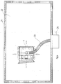
- the cleaning device 1 is located on the bottom of the basin 22 in a settling basin filled with water, in the form of a longitudinal basin 21.
- the connection adapter 19 of the cleaning unit 2 is connected to a central transfer point 24 by a flexible hose 23 for the further transport of sludge.
- sludge has accumulated on the bottom of the basin 22 of the longitudinal basin 21, which makes cleaning of the bottom of the basin 22 necessary in terms of quantity, consistency, local accumulation or other parameters, this is automatically recognized by the sensors 8, 9 and the cleaning process is initiated.
- the corresponding Output signals from the sensors 8, 9 reach the computer unit 10 as reference variables, where they are used by the expert system to generate computer output signals.
- the computer output signals forwarded to the travel control device 7 for controlling the travel drive 5 are generated primarily from the point of view of the most economical travel movement of the cleaning device 1. This essentially means that the travel distances and the duration of use should be as short as possible.
- the movement of the cleaning device 1 can take any direction on the pelvic floor 22 and the speed of the movement can be adapted to the local accumulation of the sludge.
- Another possibility, not shown in this embodiment, of reacting to different amounts of sludge to be extracted consists in an advantageous adaptation of the performance of the extraction device, which can also be controlled by the computer unit 10 by means of corresponding signals. If necessary, both options can be combined in a constructive solution to deal with the locally different amounts of sludge to be separated.
- the dimensions of the compact self-propelled cleaning device 1 are by far smaller than those of the settling basin 21. Since the dimensions of the cleaning device 1 do not require adaptation to the basin dimensions, there is the essential advantage that the cleaning device 1 can be used successively in several different pools. For example, it is easily possible to also use the cleaning device 1 for one Round pools or to use for other pool shapes. For example, a mobile crane can be used to remove and insert the cleaning device 1 into different basins. In practice, it has been shown that there are a large number of applications in which the cleaning intervals for the individual basins are large enough to use a single cleaning device in succession in several basins. This is of great economic importance for the operators of such systems, since they no longer have to procure and install their own cleaning device for each pool.
- the cleaning device according to the embodiment shown in FIG. 1 is also used.
- a telescopically adjustable length 31 is connected on one side to the connection adapter 19 with the associated adjustment drive.
- the length of the adjustable tube 31 is to be set up in such a way that the outlet side of the tube 31 is located in a trough 33 in a basin independently of the movement of the cleaning device 1 via a transfer point running parallel to the longitudinal edge 32 of the longitudinal basin 30.
- an adjustment drive of the transfer tube can be dispensed with if the outlet side of the tube 31 has a mechanical positive guide, which ensures that the tube mouth always lies above the channel 33.
- the cleaning device 1 can be moved along a pipe bridge 37 transversely to the longitudinal direction of the pool.
- the longitudinal movement is transmitted to the cleaning device 1 by the tube bridge 37 which can be moved in the longitudinal direction of the pool.
- the pipe bridge 37 can be moved parallel to the upper longitudinal edges 40 of the longitudinal pool 39 on rail guides, not shown in the drawing.
- the connection adapter 19 of the cleaning device 1 is connected to the pipe bridge 37 via a connecting hose 36.
- the substances to be separated are discharged via the hose 36 into the free interior of the pipe 38 or a corresponding channel on the pipe bridge 37. From there they arrive, analogous to the design according to FIG. 5, into a channel 41 running parallel along the upper longitudinal edge 40.
- the use of two channels 41 is also possible, which are each arranged parallel on both sides to the upper longitudinal edges 40 of the longitudinal pool 39 .
- the control of the movement of the pipe bridge 37 can also be carried out by the computer unit 10. Since the pipe bridge 37 is expediently used in addition to generating the longitudinal movement of the cleaning device 1, the moving unit 3 of the cleaning device 1 only has to produce corresponding transverse movements to the longitudinal direction of the basin 39.
- the cleaning device according to the invention according to FIG. 6 thus differs in its connection to the delivery point from the previously described embodiments. All other features of the structural unit shown in FIGS. 1 to 3, in particular with regard to the sensors and the computer unit and the possibilities resulting therefrom, are also realized in this embodiment according to the invention.
- a plurality of cleaning devices 1 can also be used in one basin.
Landscapes
- Chemical & Material Sciences (AREA)
- Chemical Kinetics & Catalysis (AREA)
- Cleaning In General (AREA)
- Sink And Installation For Waste Water (AREA)
- Filters For Electric Vacuum Cleaners (AREA)
- Separation Of Suspended Particles By Flocculating Agents (AREA)
- Vehicle Cleaning, Maintenance, Repair, Refitting, And Outriggers (AREA)
Claims (14)
- Dispositif pour la purification d'un bassin, en particulier pour enlever de la vase ou du sable, avec un dispositif de purification mobile (1) pour enlever les substances à retirer et pour les conduire à un point de déversement afin d'y être évacuées, dans lequel ce dispositif de purification (1) présente une unité de purification (2) et une unité mobile (3) qui est muni d'un dispositif de pilotage (7) et un organe moteur (5) pour produire le mouvement de déplacement sur le fond du bassin, dans lequel au moins un capteur est disposé pour déceler les substances à retirer qui s'accumulent, au moyen duquel une unité de commande déclenche et commande le mouvement de déplacement en fonction de l'accumulation des substances a retirer, caractérisé en ce qu'au moins un premier capteur (8) est prévu au niveau du dispositif de purification mobile pour détecter le lieu ou le lieu et la quantité des substances à retirer qui s'accumulent et qu'une unité d'ordinateur (10) transforme les signaux de sortie du premier capteur (8) en grandeur de commande pour appliquer des signaux de sortie d'ordinateur au dispositif de pilotage pour le déplacement mobile versatile adapté au lieu ou au lieu et à la quantité de substances accumulées, au moyen duquel le dispositif de purification (1), grâce à son unité mobile (3), en tant qu'élément modulaire, est mobile dans différentes directions selon le lieu d'amoncellement de substances accumulées.
- Dispositif selon la revendication 1, caractérisé en ce que l'unité d'ordinateur (10) est dotée d'une intelligence artificielle, grâce à laquelle dans des situations de départ identiques elle applique des signaux différents au dispositif de pilotage (7) pour optimiser le déplacement mobile du dispositif de purification (1).
- Dispositif selon les revendications 1 ou 2, caractérisé en ce qu'un deuxième capteur (9) est prévu pour constater la consistence des substances et qu'il est relié à l'unité d'ordinateur (10).
- Dispositif selon la revendication 1, caractérisé en ce que le mouvement du dispositif de purification (1) est pilotable au moyen de lignes de guidage intégrées au bassin.
- Dispositif selon la revendication 4, caractérisé en ce que ces lignes de guidage sont disposées verticalement et horizontalement sous forme de matrice.
- Dispositif selon la revendication 1, caractérisé en ce qu'un dispositif aspirateur est prévu pour enlever les substances à retirer dont la puissance d'aspiration est adaptable, grâce au moyen de l'unité d'ordinateur, aux diverses quantités de substances à retirer.
- Dispositif selon la revendication 1, caractérisé en ce que le dispositif de purification (1) est raccordé à un point de déversement central (24) par un tuyau (23) pour entraîner les substances à retirer.
- Dispositif selon la revendication 1, caractérisé en ce qu'il est prévu un pont pour tuyauterie (37) pour évacuer les substances recueillies par le dispositif de purification (1), grâce auquel les substances à évacuer sont déversées dans une rigole (33) disposée au moins sur un côté au bord du bassin.
- Dispositif selon la revendication 1, caractérisé en ce que le dispositif de purification (1) est raccordé à un tube (31) de longueur variable au-dessus d'une rigole disposée parallèlement au bord du bassin.
- Dispositif selon la revendication 5 ou 6, caractérisé en ce que le dispositif de purification (1) présente au moins deux outils de débourbage (16, 16a), ou bien des dispositifs aspirant la boue, agissant dans différentes directions de marche.
- Dispositif selon la revendication 1, caractérisé en ce que le dispositif de purification (1) comporte un réservoir intermédiaire pour les substances à retirer.
- Dispositif selon la revendication 11, caractérisé en ce que l'évacuation des substances à retirer du réservoir intermédiaire vers un point de déversement défini s'effectue en fonction du chemin parcouru par le dispositif de purification (1).
- Dispositif selon la revendication 10, caractérisé en ce que le dispositif de purification (1) mobile est muni d'au moins une lame racleuse (16, 16a) agissant sur le fond du bassin, et qu'au niveau du point de versement il est prévu une trémie de réception au fond du bassin.
- Dispositif selon la revendication 1, caractérisé en ce qu'au niveau d'un pont transversal immergé dans le bassin, au moins deux dispositifs de purification (1) commandés par des capteurs sont disposés de sorte que chaque dispositif de purification (1) recouvre un domaine de purification qui lui est attribué respectivement.
Applications Claiming Priority (2)
| Application Number | Priority Date | Filing Date | Title |
|---|---|---|---|
| DE4304375 | 1993-02-13 | ||
| DE4304375A DE4304375A1 (de) | 1993-02-13 | 1993-02-13 | Vorrichtung zur Reinigung eines Beckens |
Publications (2)
| Publication Number | Publication Date |
|---|---|
| EP0613708A1 EP0613708A1 (fr) | 1994-09-07 |
| EP0613708B1 true EP0613708B1 (fr) | 1997-07-02 |
Family
ID=6480392
Family Applications (1)
| Application Number | Title | Priority Date | Filing Date |
|---|---|---|---|
| EP94101866A Expired - Lifetime EP0613708B1 (fr) | 1993-02-13 | 1994-02-08 | Dispositif pour la purification d'un bassin |
Country Status (3)
| Country | Link |
|---|---|
| EP (1) | EP0613708B1 (fr) |
| AT (1) | ATE154889T1 (fr) |
| DE (2) | DE4304375A1 (fr) |
Families Citing this family (1)
| Publication number | Priority date | Publication date | Assignee | Title |
|---|---|---|---|---|
| DE102009040958A1 (de) * | 2009-09-11 | 2011-03-17 | Holger Pinta | Verfahren und Vorrichtung zur Steuerung des Räumerbetriebs von Langsandfängen |
Family Cites Families (5)
| Publication number | Priority date | Publication date | Assignee | Title |
|---|---|---|---|---|
| JPS5992006A (ja) * | 1982-11-19 | 1984-05-28 | Mitsubishi Electric Corp | 浄水場の沈殿池排泥制御装置 |
| JPS6261604A (ja) * | 1985-09-11 | 1987-03-18 | Toshiba Corp | 汚泥掻寄装置 |
| DE3715021A1 (de) * | 1987-05-06 | 1988-11-17 | Geiger Maschf Helmut | Raeumvorrichtung fuer ein kreisfoermiges absetzbecken |
| US5269041A (en) * | 1990-06-13 | 1993-12-14 | Allen Henry W | Remote controlled sludge removal apparatus |
| DE4100309A1 (de) * | 1991-01-08 | 1992-07-09 | Passavant Werke | Raeumgeraet fuer sehr lange becken und kanal- oder stollenfoermige gerinne |
-
1993
- 1993-02-13 DE DE4304375A patent/DE4304375A1/de not_active Ceased
-
1994
- 1994-02-08 DE DE59403235T patent/DE59403235D1/de not_active Expired - Fee Related
- 1994-02-08 EP EP94101866A patent/EP0613708B1/fr not_active Expired - Lifetime
- 1994-02-08 AT AT94101866T patent/ATE154889T1/de not_active IP Right Cessation
Also Published As
| Publication number | Publication date |
|---|---|
| DE4304375A1 (de) | 1994-08-18 |
| ATE154889T1 (de) | 1997-07-15 |
| DE59403235D1 (de) | 1997-08-07 |
| EP0613708A1 (fr) | 1994-09-07 |
Similar Documents
| Publication | Publication Date | Title |
|---|---|---|
| DE3841198C2 (fr) | ||
| DE2356697C2 (de) | Vorrichtung zum Abscheiden von Schlammflocken aus einer Trägerflüssigkeit | |
| DE2743963C2 (de) | Vorrichtung zum Abscheiden von Stoffen aus verunreinigtem Wasser | |
| DE1642432B2 (de) | Klaer- und filteranlage | |
| DE2707872C2 (fr) | ||
| DE2706642A1 (de) | Vorrichtung zum trennen zweier fluessigkeiten von unterschiedlichem spezifischem gewicht | |
| DE2401550A1 (de) | Vorrichtung zur schlammbeseitigung | |
| DE69307604T2 (de) | Ohne Zugabe von Trinkwasser arbeitende Zentrifuge zum Abscheiden von Öl aus Ölschlämmen | |
| DE2726217A1 (de) | Verfahren und vorrichtung zur schlammbeseitigung | |
| EP3564454B1 (fr) | Dispositif de séparation permettant d'éliminer des objets d'un courant d'eau et procédé de fonctionnement d'un tel dispositif de séparation | |
| EP0613708B1 (fr) | Dispositif pour la purification d'un bassin | |
| DE2929139A1 (de) | Verfahren und vorrichtung zum abtrennen von schwebstoffen aus einer schwebstoffbeladenen fluessigkeit | |
| DE69308594T2 (de) | Einrichtung zur sink-schwimmscheidung von festen partikeln | |
| DE4407343A1 (de) | Vorrichtung zum Abscheiden von Partikeln mit fester Konsistenz aus einer Flüssigkeit | |
| DE2940926A1 (de) | Verfahren und vorrichtung zum abziehen von schlamm in klaerbecken | |
| WO2000026141A1 (fr) | Installation compacte pour l'epuration mecanique d'eaux usees | |
| DE4440707B4 (de) | Vorrichtung zum Reinigen von kontaminiertem Erdreich | |
| DE3426742A1 (de) | Vorrichtung zum schlammwasserabzug fuer klaerschlammeindicker | |
| DE9302080U1 (de) | Vorrichtung zur Reinigung eines Beckens | |
| DE19726745B4 (de) | Verfahren zum Abscheiden von Teilchen | |
| DE3011339C2 (de) | Verfahren zur Reinigung der Röhren eines Kraftwerkskondensators und Einrichtung zur Durchführung des Verfahrens | |
| DE2154216A1 (en) | Inclined plate clarifier - for separation of solids from liquid suspensions | |
| DE10134945B4 (de) | Sedimentationsfilteranlage mit verbesserter Absetzleistung | |
| DE1907432C3 (de) | Einrichtung für das Schlammsaugräumen in einem rechteckigen Absetzbecken | |
| DD220074B1 (de) | Vorrichtung zur entleerung von abscheideranlagen, insbesondere von fetten und absetzbaren schwebstoffen |
Legal Events
| Date | Code | Title | Description |
|---|---|---|---|
| PUAI | Public reference made under article 153(3) epc to a published international application that has entered the european phase |
Free format text: ORIGINAL CODE: 0009012 |
|
| AK | Designated contracting states |
Kind code of ref document: A1 Designated state(s): AT BE CH DE FR GB LI |
|
| 17P | Request for examination filed |
Effective date: 19941216 |
|
| 17Q | First examination report despatched |
Effective date: 19951222 |
|
| GRAG | Despatch of communication of intention to grant |
Free format text: ORIGINAL CODE: EPIDOS AGRA |
|
| GRAG | Despatch of communication of intention to grant |
Free format text: ORIGINAL CODE: EPIDOS AGRA |
|
| GRAG | Despatch of communication of intention to grant |
Free format text: ORIGINAL CODE: EPIDOS AGRA |
|
| GRAH | Despatch of communication of intention to grant a patent |
Free format text: ORIGINAL CODE: EPIDOS IGRA |
|
| GRAH | Despatch of communication of intention to grant a patent |
Free format text: ORIGINAL CODE: EPIDOS IGRA |
|
| GRAA | (expected) grant |
Free format text: ORIGINAL CODE: 0009210 |
|
| AK | Designated contracting states |
Kind code of ref document: B1 Designated state(s): AT BE CH DE FR GB LI |
|
| REF | Corresponds to: |
Ref document number: 154889 Country of ref document: AT Date of ref document: 19970715 Kind code of ref document: T |
|
| REG | Reference to a national code |
Ref country code: CH Ref legal event code: EP |
|
| REF | Corresponds to: |
Ref document number: 59403235 Country of ref document: DE Date of ref document: 19970807 |
|
| GBT | Gb: translation of ep patent filed (gb section 77(6)(a)/1977) |
Effective date: 19970717 |
|
| ET | Fr: translation filed | ||
| REG | Reference to a national code |
Ref country code: CH Ref legal event code: NV Representative=s name: A. BRAUN, BRAUN, HERITIER, ESCHMANN AG PATENTANWAE |
|
| PLBE | No opposition filed within time limit |
Free format text: ORIGINAL CODE: 0009261 |
|
| STAA | Information on the status of an ep patent application or granted ep patent |
Free format text: STATUS: NO OPPOSITION FILED WITHIN TIME LIMIT |
|
| 26N | No opposition filed | ||
| REG | Reference to a national code |
Ref country code: GB Ref legal event code: IF02 |
|
| PGFP | Annual fee paid to national office [announced via postgrant information from national office to epo] |
Ref country code: GB Payment date: 20020129 Year of fee payment: 9 |
|
| PGFP | Annual fee paid to national office [announced via postgrant information from national office to epo] |
Ref country code: BE Payment date: 20020205 Year of fee payment: 9 |
|
| PGFP | Annual fee paid to national office [announced via postgrant information from national office to epo] |
Ref country code: CH Payment date: 20020218 Year of fee payment: 9 |
|
| PGFP | Annual fee paid to national office [announced via postgrant information from national office to epo] |
Ref country code: AT Payment date: 20020227 Year of fee payment: 9 |
|
| PGFP | Annual fee paid to national office [announced via postgrant information from national office to epo] |
Ref country code: DE Payment date: 20020304 Year of fee payment: 9 |
|
| PG25 | Lapsed in a contracting state [announced via postgrant information from national office to epo] |
Ref country code: FR Free format text: LAPSE BECAUSE OF NON-PAYMENT OF DUE FEES Effective date: 20021031 |
|
| REG | Reference to a national code |
Ref country code: FR Ref legal event code: ST |
|
| PG25 | Lapsed in a contracting state [announced via postgrant information from national office to epo] |
Ref country code: GB Free format text: LAPSE BECAUSE OF NON-PAYMENT OF DUE FEES Effective date: 20030208 Ref country code: AT Free format text: LAPSE BECAUSE OF NON-PAYMENT OF DUE FEES Effective date: 20030208 |
|
| PG25 | Lapsed in a contracting state [announced via postgrant information from national office to epo] |
Ref country code: LI Free format text: LAPSE BECAUSE OF NON-PAYMENT OF DUE FEES Effective date: 20030228 Ref country code: CH Free format text: LAPSE BECAUSE OF NON-PAYMENT OF DUE FEES Effective date: 20030228 Ref country code: BE Free format text: LAPSE BECAUSE OF NON-PAYMENT OF DUE FEES Effective date: 20030228 |
|
| PGFP | Annual fee paid to national office [announced via postgrant information from national office to epo] |
Ref country code: FR Payment date: 20030314 Year of fee payment: 10 |
|
| REG | Reference to a national code |
Ref country code: FR Ref legal event code: RN |
|
| PG25 | Lapsed in a contracting state [announced via postgrant information from national office to epo] |
Ref country code: DE Free format text: LAPSE BECAUSE OF NON-PAYMENT OF DUE FEES Effective date: 20030902 |
|
| GBPC | Gb: european patent ceased through non-payment of renewal fee | ||
| REG | Reference to a national code |
Ref country code: CH Ref legal event code: PL |
|
| REG | Reference to a national code |
Ref country code: FR Ref legal event code: IC |