EP0614045A1 - Procédé et dispositif d'alimentation à plusieurs débits de mélanges air-gaz pour un brûleur à prémélange - Google Patents
Procédé et dispositif d'alimentation à plusieurs débits de mélanges air-gaz pour un brûleur à prémélange Download PDFInfo
- Publication number
- EP0614045A1 EP0614045A1 EP94200531A EP94200531A EP0614045A1 EP 0614045 A1 EP0614045 A1 EP 0614045A1 EP 94200531 A EP94200531 A EP 94200531A EP 94200531 A EP94200531 A EP 94200531A EP 0614045 A1 EP0614045 A1 EP 0614045A1
- Authority
- EP
- European Patent Office
- Prior art keywords
- air
- burner
- gas
- shutter
- tubular body
- Prior art date
- Legal status (The legal status is an assumption and is not a legal conclusion. Google has not performed a legal analysis and makes no representation as to the accuracy of the status listed.)
- Withdrawn
Links
Images


Classifications
-
- F—MECHANICAL ENGINEERING; LIGHTING; HEATING; WEAPONS; BLASTING
- F23—COMBUSTION APPARATUS; COMBUSTION PROCESSES
- F23N—REGULATING OR CONTROLLING COMBUSTION
- F23N1/00—Regulating fuel supply
- F23N1/02—Regulating fuel supply conjointly with air supply
- F23N1/027—Regulating fuel supply conjointly with air supply using mechanical means
-
- F—MECHANICAL ENGINEERING; LIGHTING; HEATING; WEAPONS; BLASTING
- F23—COMBUSTION APPARATUS; COMBUSTION PROCESSES
- F23D—BURNERS
- F23D14/00—Burners for combustion of a gas, e.g. of a gas stored under pressure as a liquid
- F23D14/34—Burners specially adapted for use with means for pressurising the gaseous fuel or the combustion air
- F23D14/36—Burners specially adapted for use with means for pressurising the gaseous fuel or the combustion air in which the compressor and burner form a single unit
-
- F—MECHANICAL ENGINEERING; LIGHTING; HEATING; WEAPONS; BLASTING
- F23—COMBUSTION APPARATUS; COMBUSTION PROCESSES
- F23D—BURNERS
- F23D14/00—Burners for combustion of a gas, e.g. of a gas stored under pressure as a liquid
- F23D14/46—Details
- F23D14/60—Devices for simultaneous control of gas and combustion air
Definitions
- This invention relates to a method for feeding air/gas mixtures at varying flow rates to a so-called fully premixed burner in a heating apparatus which includes a circuit for disposing of the flue gas downstream from the burner, the method comprising the steps of: conveying an air flow into a tubular body by means of a blower; conveying a separate flow of a fuel gas into said tubular body through a respective supply conduit; controlling the rate of said gas flow by throttling said conduit; mixing said air and gas flows together through a mixing path formed in said tubular body, and delivering the resultant mixture to the burner over a supply conduit.
- the invention concerns a method for feeding air/gas mixtures to premix burners employed in heating apparatus for civil applications, such as flash boilers or water heaters.
- the invention is also directed to a device for implementing the method.
- blowwer will be used throughout the description here below and the appended claims to indicate any air supply arrangement -- including a centrifugal fan -- of the type wherein, for each change in the delivery flow rate there corresponds an oppositely directed change in the air delivery pressure.
- the former is of paramount importance in this case, as a controlled delivery of thermal power according to the user's own requirements should be ensured as fully as possible.
- blast burners have been mainly employed in this field wherein the combustion air is partly premixed with the fuel gas downstream from the burner gas delivery nozzles (primary air), and partly supplied downstream from the burner to complete the combustion (secondary air).
- Blast burners while providing for the desired control of thermal power, do require to be operated with considerable excess air over the stoichiometric amount in order to ensure as complete a gas combustion as possible.
- the function of feeding burners of this type with air/gas mixtures having the desired characteristics is usually served by devices wherein separate flows of air and fuel gas from a centrifugal fan and the gas distribution network, for example, are mixed together in metered amounts which can be varied according to the thermal power delivered by the burner.
- the flow rates of the air and gas fed to the burner are controlled by changing the centrifugal fan rpm and throttling the gas supply conduit connected to the external distribution network, respectively.
- the fuel gas supply conduit is throttled using valve means driven to conform with changes in the air flow rate by a device which comprises a diaphragm and a complex lever arrangement for mechanical amplification.
- the means provided to change the gas flow rate according to the air flow rate have, however, significant drawbacks originating from their construction and operation.
- a first of said drawbacks comes from the limitations to which the diapnragm provided for measuring the presence and magnitude of each variation in the air flow rate is subject; its dimensioning, in fact, disallows minor variations in the air flow rate to be "perceived", with consequent failure to adjust the gas flow rate.
- an attempt at obviating these drawbacks provides for of the air and gas flow rates to be controlled through an electronic control system capable of varying said flow rates independently and simultaneously by acting on the centrifugal fan rpm and the valve means for throttling the fuel gas supply conduit, respectively.
- the underlying technical problem of this invention is, therefore, to provide a method which can allow air/gas mixtures to be fed at variable rates to a so-called fully premixed burner, and at the same time overcome the drawbacks with which the aforementioned prior art is beset.
- the air flow from the blower is diverted into the bypass conduit, with no appreciable changes in overall head loss and without changing the blower rpm, through a shutter which is guided slidably within an air distribution chamber interposed between the blower and the mixing path.
- this invention provides a device of a type comprising a tubular body having an air/gas mixing path defined therein which is in fluid communication with an air delivery blower and a fuel gas supply conduit, said tubular body having an outlet opening facing a burner supply conduit, and being characterized in that it further comprises, located upstream of said mixing path, an air distribution chamber provided with an air inlet passageway in fluid communication with said blower, and opposed air outlet passageways facing said mixing path and a burner bypass conduit, respectively, valve means being provided in said chamber to selectively divert predetermined amounts of air toward said tubular body and said bypass conduit, respectively.
- Said boiler includes, downstream from the burner 2, a circuit 40 for disposing of the flue gas which comprises a chamber 41 wherein a gas/water heat exchanger 42 is carried to generate heated water for space heating purposes, for example, in fluid communication with a hood, known per se and not shown.
- the circuit 40 is, in turn, connected to a chimney, also known per se and not shown, for exhausting the flue gas to the ambience.
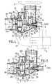
- the device 1 comprises a substantially L-shaped tubular body 3 having an air and fuel gas mixing path 4 defined on its interior.
- the latter is in fluid communication, at one end with the burner 2 through a conduit 9, and at the other end with an air distribution chamber 10 interposed between the tubular body 3 and a blower 5, e.g. a centrifugal fan, to which it is connected by a conduit 11.
- a blower 5 e.g. a centrifugal fan
- inlet openings for admitting air and fuel gas into the device 1 which are conventionally associated with the centrifugal fan 5 and with a conduit 6 connected to the external gas distribution network, and shown at 12 is an outlet opening for the air/gas mixture facing the burner 2.
- the chamber 10 is advantageously made of a plastics material and comprises two juxtaposed shells 10a, 10b which are associated with each other in a manner known per se, such as by a plurality of screws 43 threaded into eyelets 44, in turn formed by the junction of mating portions 44a, 44b extending integrally from the shells.
- the chamber 10 is mounted releasably to the tubular body 3 by means of a plurality of screws, collectively indicated at 45 and threadably engaged in corresponding supporting lugs 46 formed integrally on the tubular body exterior.
- the chamber 10 and tubular body 3 can be associated together at the most appropriate position for mounting the device 1 on the boiler.
- the chamber 10 is advantageously a scroll pattern, so as to convey the air from the centrifugal fan 5 toward the mixing path 4 with a minimum of head loss.
- the chamber 10 is provided, downstream from said air inlet opening 7, with opposed air outlet passageways 13, 14 leading to the mixing path 4 and a bypass conduit 15 of the burner 2, respectively.
- the conduit 15 is, in turn, connected, in a manner known per se and not shown, to the chimney for disposing of the flue gas from the circuit 40 inclusive of the burner 2.
- This conduit 15 may be provided, where desired, with one or more diaphragms effective to induce a head loss in the air passageway which is substantially equivalent to that induced by the combination of the tubular body 3, the conduit 9, the burner 2 and the circuit 40.
- valve means 16 are provided within the chamber 10 to selectively divert predetermined amounts of air toward the tubular body 3 and/or the bypass conduit 15, respectively.
- valve means 16 comprise a substantially disk-shaped shutter 17 which is guided slidably within the chamber 10 for adjustable movement between opposed positions whereat it respectively opens and closes each of the air outlet passageways 13 and 14.
- valve means 16 are provided with an actuator device 18 which comprises an electric step motor 19 housed within the shutter 17 and driven in a manner known per se, e.g. through a conventional control unit, not shown, from a thermostat schematically shown at 37.
- actuator device 18 which comprises an electric step motor 19 housed within the shutter 17 and driven in a manner known per se, e.g. through a conventional control unit, not shown, from a thermostat schematically shown at 37.
- a cable is schematically shown at 20 which connects the step motor 19 electrically to said unit.
- the actuator device 18 further includes a threaded shaft 21 which is driven rotatively by the step motor 19 to threadably engage in a threaded hole 22 provided in a bush 23 extending axially in the air outlet passageway 14, where it is supported by three radial webs 24a, 24b and 24c forming angles of about 120 degrees between each other.
- Indicated at 25 is a key, extending integrally from the shutter 17, which engages slidably in a respective mating seat 26 arranged to face it within the chamber 10.
- the actuator device 18 for the shutter 17 also drives valve means 27 to open/close which are accommodated downstream from the fuel gas supply conduit 6 and lie in the mixing path 4.
- Said valve means 27 comprise a substantially L-shaped valve body 28 wherethrough a fuel gas path 39 is defined which extends between opposed gas inlet 29 and gas outlet 30 passageways housing a nozzle 31 and a fuel gas distribution head 32, respectively,. in the tubular body 3.
- the nozzle 31 is outside threaded for screw engagement with the gas inlet passageway 29, in which it can be positioned in an adjustable manner.
- the rod 36 extends from the shutter 17 on the opposite side from the shaft 21, wherewith it lies substantially coaxial.
- the shutter 34 may be given such a shape, e.g. by selecting a suitable flare angle for the cone, as to allow the flow rate of the fuel gas conveyed along the mixing path 4 to be varied at will and as expected.
- the head 32 is given a substantially truncated cone shape and has three radial supporting webs, collectively designated 38, arranged at an offset angle of 120 degrees from one another and co-operating with the valve body 28, in abutting relationship therewith, to define three annular outlet slots for the fuel gas from the valve means 27.
- the device 1 effects the mixing of air from the centrifugal fan 5 with the gas from the conduit 6 at the distribution head 32 along the mixing path 4.
- the shutter 17 occupies a first position where it shuts off the air outlet passageway 14 to the bypass conduit 15, thereby directing the air flow from the centrifugal fan 5 fully along the mixing path 4, i.e. to the burner 2.
- the shutter 34 in turn occupies a position where the fuel gas delivery nozzle 31 is opened wide.
- the thermostat 37 When the thermal power delivered by the burner 2 requires to be decreased the thermostat 37 will, through the step motor 19, drive the shutter 17 to open the bypass conduit 15.
- the invention provides for the shutter 17 to be positioned inside the chamber 10, in an adjustable manner by rotating the shaft 21 in the bush 22 to correspondingly traverse the shutter 17, whose sliding movement will be guided by the key 25.
- the shutter 17 displacement will simply divert an aliquot of the air flow from the centrifugal fan 5 toward the bypass conduit 15, with no significant change in overall head loss downstream of the chamber 10, that is without causing any significant alteration of the fan conditions of operation.
- the air flow rate to the burner can advantageously be controlled by just changing the shutter 17 setting within the chamber 10.
- each displacement of the shutter 17 within the chamber 10 results in a corresponding displacement of the shutter 34 toward the inlet 33 of the nozzle 31 to throttle down the passage therethrough and concurrently control the fuel gas flow rate.
- the thermostat 37 will position the shutters 17 and 34 such that the burner 2 is supplied the appropriate air/gas mixture for optimum combustion.
- a first major advantage is that a so-called fully premixed burner can be supplied air/gas mixtures at varying flow rates in an extremely simple and reliable manner.
- the invention allows, for example, a near-stoichiometric air/gas ratio to be selected at maximum power of the burner 2, and a higher (excess air) air/gas ratio at minimum thermal power, to best exploit the potential of the fully premixed burner.
- the delivery of "cool" air to the chimney through the bypass conduit 15 has further advantages in that it increases the draft in boilers of the so-called natural draft type, and lowers the dew point of the flue gas, thereby attenuating the risk of condensate forming on the chimney interior.
- the inventive device is, moreover, a so-called inherently safe type, that is, in the event of a failure, the device operation would enter a condition of steady state operation because of the air and gas being always mixed in precisely balanced ratii from the stoichiometric standpoint.
- the invention provides a device which is simple, can be adapted at the assembly stage for a wide range of different boiler designs, is reliable in operation, and includes elements which can be mass produced at a low cost using conventional techniques in the industry.
Landscapes
- Engineering & Computer Science (AREA)
- Chemical & Material Sciences (AREA)
- Combustion & Propulsion (AREA)
- Mechanical Engineering (AREA)
- General Engineering & Computer Science (AREA)
- Regulation And Control Of Combustion (AREA)
- Gas Burners (AREA)
Applications Claiming Priority (2)
| Application Number | Priority Date | Filing Date | Title |
|---|---|---|---|
| ITMI930436 | 1993-03-05 | ||
| ITMI930436A IT1271987B (it) | 1993-03-05 | 1993-03-05 | Metodo per alimentare miscele aria/gas a portata variabile ad un bruciatore cosidetto a completa premiscelazione e dispositivo per la attuazione di esso |
Publications (1)
| Publication Number | Publication Date |
|---|---|
| EP0614045A1 true EP0614045A1 (fr) | 1994-09-07 |
Family
ID=11365271
Family Applications (1)
| Application Number | Title | Priority Date | Filing Date |
|---|---|---|---|
| EP94200531A Withdrawn EP0614045A1 (fr) | 1993-03-05 | 1994-03-02 | Procédé et dispositif d'alimentation à plusieurs débits de mélanges air-gaz pour un brûleur à prémélange |
Country Status (2)
| Country | Link |
|---|---|
| EP (1) | EP0614045A1 (fr) |
| IT (1) | IT1271987B (fr) |
Cited By (7)
| Publication number | Priority date | Publication date | Assignee | Title |
|---|---|---|---|---|
| WO2002095294A1 (fr) | 2001-05-18 | 2002-11-28 | Furigas Assen B.V. | Bruleurs a gaz a premelange sans condensation |
| FR2981863A1 (fr) * | 2011-10-26 | 2013-05-03 | Gdf Suez | Dispositif de regulation d'un melange gazeux |
| CN104116420A (zh) * | 2013-04-25 | 2014-10-29 | 神宝股份有限公司 | 加热调理器 |
| EP3211305A1 (fr) * | 2016-02-02 | 2017-08-30 | Daesung Celtic Enersys Co., Ltd. | Vanne de modulation |
| JP2019011900A (ja) * | 2017-06-30 | 2019-01-24 | リンナイ株式会社 | 予混合装置 |
| US20210404706A1 (en) * | 2020-06-24 | 2021-12-30 | A.O. Smith (China) Water Heater Co., Ltd. | Gas mixing device and gas water heating device |
| US20220228743A1 (en) * | 2020-06-24 | 2022-07-21 | A.O. Smith (China) Water Heater Co., Ltd. | Gas mixing device and gas water heating device |
Citations (3)
| Publication number | Priority date | Publication date | Assignee | Title |
|---|---|---|---|---|
| JPS5310145A (en) * | 1976-07-16 | 1978-01-30 | Matsushita Electric Ind Co Ltd | Forcible inhaling and exhaling burning equipment |
| EP0309034A1 (fr) * | 1987-09-15 | 1989-03-29 | Flameco-Eclipse B.V. | Brûleur à gaz |
| EP0508164A1 (fr) * | 1991-03-30 | 1992-10-14 | Ruhrgas Aktiengesellschaft | Dispositif de contrôle du débit et/ou du rapport de mélange d'un mélange combustible gazeux-air |
-
1993
- 1993-03-05 IT ITMI930436A patent/IT1271987B/it active IP Right Grant
-
1994
- 1994-03-02 EP EP94200531A patent/EP0614045A1/fr not_active Withdrawn
Patent Citations (3)
| Publication number | Priority date | Publication date | Assignee | Title |
|---|---|---|---|---|
| JPS5310145A (en) * | 1976-07-16 | 1978-01-30 | Matsushita Electric Ind Co Ltd | Forcible inhaling and exhaling burning equipment |
| EP0309034A1 (fr) * | 1987-09-15 | 1989-03-29 | Flameco-Eclipse B.V. | Brûleur à gaz |
| EP0508164A1 (fr) * | 1991-03-30 | 1992-10-14 | Ruhrgas Aktiengesellschaft | Dispositif de contrôle du débit et/ou du rapport de mélange d'un mélange combustible gazeux-air |
Non-Patent Citations (1)
| Title |
|---|
| PATENT ABSTRACTS OF JAPAN vol. 2, no. 50 (M - 015) 10 April 1978 (1978-04-10) * |
Cited By (13)
| Publication number | Priority date | Publication date | Assignee | Title |
|---|---|---|---|---|
| WO2002095294A1 (fr) | 2001-05-18 | 2002-11-28 | Furigas Assen B.V. | Bruleurs a gaz a premelange sans condensation |
| JP2014534406A (ja) * | 2011-10-26 | 2014-12-18 | ジェデエフ スエズ | ガス混合気を調整するための装置 |
| FR2981863A1 (fr) * | 2011-10-26 | 2013-05-03 | Gdf Suez | Dispositif de regulation d'un melange gazeux |
| WO2013060997A3 (fr) * | 2011-10-26 | 2013-10-24 | Gdf Suez | Dispositif de régulation d'un mélange gazeux |
| CN104116420B (zh) * | 2013-04-25 | 2018-01-16 | 神宝股份有限公司 | 加热调理器 |
| CN104116420A (zh) * | 2013-04-25 | 2014-10-29 | 神宝股份有限公司 | 加热调理器 |
| EP3211305A1 (fr) * | 2016-02-02 | 2017-08-30 | Daesung Celtic Enersys Co., Ltd. | Vanne de modulation |
| US10168074B2 (en) | 2016-02-02 | 2019-01-01 | DAESUNG CELTIC ENERSYS Co., Ltd | Turn down ratio (TDR) damper |
| JP2019011900A (ja) * | 2017-06-30 | 2019-01-24 | リンナイ株式会社 | 予混合装置 |
| US20210404706A1 (en) * | 2020-06-24 | 2021-12-30 | A.O. Smith (China) Water Heater Co., Ltd. | Gas mixing device and gas water heating device |
| US20220228743A1 (en) * | 2020-06-24 | 2022-07-21 | A.O. Smith (China) Water Heater Co., Ltd. | Gas mixing device and gas water heating device |
| US11585573B2 (en) * | 2020-06-24 | 2023-02-21 | A. O. Smith Corporation | Gas mixing device and gas water heating device |
| US11808453B2 (en) | 2020-06-24 | 2023-11-07 | A.O. Smith Corporation | Gas mixing device and gas water heating device |
Also Published As
| Publication number | Publication date |
|---|---|
| ITMI930436A0 (it) | 1993-03-05 |
| ITMI930436A1 (it) | 1994-09-05 |
| IT1271987B (it) | 1997-06-10 |
Similar Documents
| Publication | Publication Date | Title |
|---|---|---|
| EP3772614B1 (fr) | Appareil de prémélange | |
| US8506290B2 (en) | Heating apparatus with air shutter adjustment | |
| USRE46308E1 (en) | Dual fuel heater | |
| CN106662323B (zh) | 具有文丘里管阻尼器的可调节燃烧器 | |
| EP1356234B1 (fr) | Melangeur air-gaz ameliore | |
| US20110290229A1 (en) | Dual Fuel Vent Free Gas Heater | |
| US4436506A (en) | Control system for a gas heated water or air heater | |
| US4644967A (en) | Fluid flow control system | |
| EP3765792B1 (fr) | Dispositif de chauffage à combustibles solides ayant une alimentation en air de combustion à trois zones | |
| US7789657B2 (en) | Pressure regulator with bleed orifice | |
| EP0614045A1 (fr) | Procédé et dispositif d'alimentation à plusieurs débits de mélanges air-gaz pour un brûleur à prémélange | |
| CA2229129C (fr) | Soupape a gaz modulee par pression differentielle pour le reglage de la combustion mono-etagee | |
| US2178703A (en) | Fuel burning apparatus | |
| US4547144A (en) | Fuel gas control | |
| US5549099A (en) | Injection and regulation device for atmospheric gas burners for heating appliance, in particular of the infra-red type | |
| US2821246A (en) | Combination oil-gas burner and gas burner adapter for gun-type oil burner | |
| EP0275568A1 (fr) | Dispositif à gaz pour eau chaude comprenant un ventilateur d'alimentation et une commande modulée de gaz et d'air | |
| KR102146268B1 (ko) | 온수 설비를 위한 혼합물 공급 시스템, 연료와 산화제를 섞기 위한 방법 및 상기 혼합물 공급 시스템을 포함하는 온수 설비 | |
| EP0894224B1 (fr) | Systeme de chauffage infrarouge et element de mesure | |
| CN112050284B (zh) | 多气源取暖器 | |
| EP0697563A1 (fr) | Assemblage de soupape pour chaudière à gaz | |
| GB2272510A (en) | Combustion chamber housing assembly for a gas turbine | |
| EP0169689B1 (fr) | Système de chauffage infrarouge | |
| CN116981884A (zh) | 部分预混合的燃气燃烧器器具 | |
| JP2017067409A (ja) | 複合熱源機 |
Legal Events
| Date | Code | Title | Description |
|---|---|---|---|
| PUAI | Public reference made under article 153(3) epc to a published international application that has entered the european phase |
Free format text: ORIGINAL CODE: 0009012 |
|
| AK | Designated contracting states |
Kind code of ref document: A1 Designated state(s): DE FR GB NL |
|
| 17P | Request for examination filed |
Effective date: 19941217 |
|
| 17Q | First examination report despatched |
Effective date: 19960507 |
|
| STAA | Information on the status of an ep patent application or granted ep patent |
Free format text: STATUS: THE APPLICATION IS DEEMED TO BE WITHDRAWN |
|
| 18D | Application deemed to be withdrawn |
Effective date: 19961119 |