EP0614065A1 - Pyrotechnischer Gefechtskopf mit verbesserter Streuvorrichtung - Google Patents
Pyrotechnischer Gefechtskopf mit verbesserter Streuvorrichtung Download PDFInfo
- Publication number
- EP0614065A1 EP0614065A1 EP94400453A EP94400453A EP0614065A1 EP 0614065 A1 EP0614065 A1 EP 0614065A1 EP 94400453 A EP94400453 A EP 94400453A EP 94400453 A EP94400453 A EP 94400453A EP 0614065 A1 EP0614065 A1 EP 0614065A1
- Authority
- EP
- European Patent Office
- Prior art keywords
- envelope
- pyrotechnic
- head according
- longitudinal
- substance
- Prior art date
- Legal status (The legal status is an assumption and is not a legal conclusion. Google has not performed a legal analysis and makes no representation as to the accuracy of the status listed.)
- Granted
Links
Images

Classifications
-
- F—MECHANICAL ENGINEERING; LIGHTING; HEATING; WEAPONS; BLASTING
- F42—AMMUNITION; BLASTING
- F42B—EXPLOSIVE CHARGES, e.g. FOR BLASTING, FIREWORKS, AMMUNITION
- F42B12/00—Projectiles, missiles or mines characterised by the warhead, the intended effect, or the material
- F42B12/02—Projectiles, missiles or mines characterised by the warhead, the intended effect, or the material characterised by the warhead or the intended effect
- F42B12/36—Projectiles, missiles or mines characterised by the warhead, the intended effect, or the material characterised by the warhead or the intended effect for dispensing materials; for producing chemical or physical reaction; for signalling ; for transmitting information
-
- F—MECHANICAL ENGINEERING; LIGHTING; HEATING; WEAPONS; BLASTING
- F42—AMMUNITION; BLASTING
- F42B—EXPLOSIVE CHARGES, e.g. FOR BLASTING, FIREWORKS, AMMUNITION
- F42B12/00—Projectiles, missiles or mines characterised by the warhead, the intended effect, or the material
- F42B12/02—Projectiles, missiles or mines characterised by the warhead, the intended effect, or the material characterised by the warhead or the intended effect
- F42B12/36—Projectiles, missiles or mines characterised by the warhead, the intended effect, or the material characterised by the warhead or the intended effect for dispensing materials; for producing chemical or physical reaction; for signalling ; for transmitting information
- F42B12/44—Projectiles, missiles or mines characterised by the warhead, the intended effect, or the material characterised by the warhead or the intended effect for dispensing materials; for producing chemical or physical reaction; for signalling ; for transmitting information of incendiary type
-
- F—MECHANICAL ENGINEERING; LIGHTING; HEATING; WEAPONS; BLASTING
- F42—AMMUNITION; BLASTING
- F42B—EXPLOSIVE CHARGES, e.g. FOR BLASTING, FIREWORKS, AMMUNITION
- F42B12/00—Projectiles, missiles or mines characterised by the warhead, the intended effect, or the material
- F42B12/02—Projectiles, missiles or mines characterised by the warhead, the intended effect, or the material characterised by the warhead or the intended effect
- F42B12/36—Projectiles, missiles or mines characterised by the warhead, the intended effect, or the material characterised by the warhead or the intended effect for dispensing materials; for producing chemical or physical reaction; for signalling ; for transmitting information
- F42B12/46—Projectiles, missiles or mines characterised by the warhead, the intended effect, or the material characterised by the warhead or the intended effect for dispensing materials; for producing chemical or physical reaction; for signalling ; for transmitting information for dispensing gases, vapours, powders or chemically-reactive substances
-
- F—MECHANICAL ENGINEERING; LIGHTING; HEATING; WEAPONS; BLASTING
- F42—AMMUNITION; BLASTING
- F42B—EXPLOSIVE CHARGES, e.g. FOR BLASTING, FIREWORKS, AMMUNITION
- F42B12/00—Projectiles, missiles or mines characterised by the warhead, the intended effect, or the material
- F42B12/02—Projectiles, missiles or mines characterised by the warhead, the intended effect, or the material characterised by the warhead or the intended effect
- F42B12/36—Projectiles, missiles or mines characterised by the warhead, the intended effect, or the material characterised by the warhead or the intended effect for dispensing materials; for producing chemical or physical reaction; for signalling ; for transmitting information
- F42B12/46—Projectiles, missiles or mines characterised by the warhead, the intended effect, or the material characterised by the warhead or the intended effect for dispensing materials; for producing chemical or physical reaction; for signalling ; for transmitting information for dispensing gases, vapours, powders or chemically-reactive substances
- F42B12/48—Projectiles, missiles or mines characterised by the warhead, the intended effect, or the material characterised by the warhead or the intended effect for dispensing materials; for producing chemical or physical reaction; for signalling ; for transmitting information for dispensing gases, vapours, powders or chemically-reactive substances smoke-producing, e.g. infrared clouds
-
- F—MECHANICAL ENGINEERING; LIGHTING; HEATING; WEAPONS; BLASTING
- F42—AMMUNITION; BLASTING
- F42B—EXPLOSIVE CHARGES, e.g. FOR BLASTING, FIREWORKS, AMMUNITION
- F42B12/00—Projectiles, missiles or mines characterised by the warhead, the intended effect, or the material
- F42B12/02—Projectiles, missiles or mines characterised by the warhead, the intended effect, or the material characterised by the warhead or the intended effect
- F42B12/36—Projectiles, missiles or mines characterised by the warhead, the intended effect, or the material characterised by the warhead or the intended effect for dispensing materials; for producing chemical or physical reaction; for signalling ; for transmitting information
- F42B12/46—Projectiles, missiles or mines characterised by the warhead, the intended effect, or the material characterised by the warhead or the intended effect for dispensing materials; for producing chemical or physical reaction; for signalling ; for transmitting information for dispensing gases, vapours, powders or chemically-reactive substances
- F42B12/50—Projectiles, missiles or mines characterised by the warhead, the intended effect, or the material characterised by the warhead or the intended effect for dispensing materials; for producing chemical or physical reaction; for signalling ; for transmitting information for dispensing gases, vapours, powders or chemically-reactive substances by dispersion
Definitions
- the present invention relates to the field of pyrotechnic heads.
- the present invention relates more precisely to a pyrotechnic head intended mainly for dispersing in contact with or near a target a pyrotechnic composition comprising one or more pyrotechnic substances chosen according to the desired effect, incendiary and / or incapacitating.
- a pyrotechnic head comprising an envelope filled with a pyrotechnic composition and means for dispersing this composition on the target, conventionally a charge explosive placed within the pyrotechnic composition.
- the envelope ruptures under the effect of the pressure released when the explosive charge explodes.
- Known pyrotechnic heads of this type have the disadvantage of causing an irregular bursting of the envelope and the dispersion of the pyrotechnic composition takes place in directions and with an extent which does not always correspond to the desired dispersion.
- the dispersion must not be too wide because the substance becomes difficult to ignite or too confined because it then loses effectiveness.
- Publication US-A-3,103,888 describes a pyrotechnic head comprising an elongated envelope, a smoke pyrotechnic composition consisting of white phosphorus contained in the envelope and dispersing means for dispersing the latter and cutting the envelope longitudinally.
- the dispersing means are arranged in this known pyrotechnic head so that the white phosphorus is little dispersed and burns in the form of large pieces in the manner of smoke pots.
- this known head is not suitable for an incendiary or incapacitating composition where a wider spread is sought.
- the present invention aims to propose a pyrotechnic head comprising an elongated envelope comprising a cylindrical body of revolution about an axis of symmetry, closed at the rear by a bottom, a pyrotechnic composition contained in the envelope and means of dispersion for dispersing said pyrotechnic composition, overcoming the aforementioned drawbacks, in particular which does not require costly machining for its production, which ensures regular dispersion of the pyrotechnic composition and the widest possible for the desired application.
- the dispersing means comprise longitudinal detonating cutting cords adapted to cut the envelope longitudinally, a transverse detonating cutting cord suitable for cutting the envelope transversely, said transverse detonating cutting cord being placed on the periphery of the internal surface of the envelope in front of the bottom.
- the transverse detonating cord opens the envelope at the rear and thus facilitates, with the action of the longitudinal cords, the dispersion of the composition.
- said pyrotechnic composition comprises an incendiary substance and a pyrogenic substance suitable for lighting the latter, the two substances being placed in separate compartments inside the envelope.
- the envelope is closed at the front by a nose which is generally convex towards the outside, the pyrogenic substance is placed in the nose of the envelope and the incendiary substance in the cylindrical body.
- said pyrotechnic composition further comprises a tear gas substance placed in a compartment located in the nose of the envelope, opposite the compartment containing the incendiary substance.
- the pyrotechnic head comprises an explosive pin placed in front of the compartment containing said pyrogenic substance.
- the explosive piece is placed between the compartment containing the tear substance and that containing the pyrogenic substance.
- the pyrotechnic head comprises pyrotechnic initiation means extending from the rear of the envelope forwards to the explosive pin.
- said pyrotechnic initiation means are placed in the center of the envelope and extend along said axis of symmetry of the envelope.
- the transverse detonating cord is placed near at least one longitudinal detonating cord so that the initiation of the transverse detonating cord is carried out by the longitudinal detonating cords.
- the transverse detonating cord is placed at a distance from the axial ends of the longitudinal detonating cords, and preferably placed at a distance between a quarter and an eighth of their length.
- said pyrotechnic initiation means are placed near the longitudinal detonating cords so that said pyrotechnic initiation means initiate the longitudinal detonating cords which in turn initiate the transverse detonating cord.
- the longitudinal detonating cords are placed on the internal surface of the envelope.
- the longitudinal detonating cords each extend in a plane containing the axis of symmetry of the envelope.
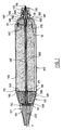
- FIG. 1 a pyrotechnic head according to the invention, intended to be preferably equipped with a stabilizer known in itself and not shown to form a projectile.
- the rear part and the front part respectively designate the parts of the head respectively closest and furthest from this empennage, the rear part being located on the right in FIG. 1.
- the pyrotechnic head comprises an envelope 100 preferably symmetrical in revolution around an axis referenced X contained in the section plane in FIG. 1.
- the envelope 100 comprises a cylindrical body 110 of revolution around the axis X, extended to the rear by a generally convex outwardly symmetrical bottom of revolution about the axis X, formed with the cylindrical body 110 or attached to the latter.
- the cylindrical body 110 is closed at the front by a nose 125.
- the latter comprises a frustoconical intermediate hollow body 128, symmetrical about revolution around the axis X, located in front of the cylindrical body 110 and assembled by screwing in 126 on that and a hollow end body 127 situated in front of the intermediate body 128 and assembled by screwing at 129 thereon.
- the intermediate hollow body 128 comprises a frustoconical wall widening towards the rear, connected at the rear to a wall 144 perpendicular to the axis X, provided in its center with a circular passage 171 and a cylindrical skirt 172 internally threaded, extending the wall 144 rearwards at its outer periphery to be screwed onto the cylindrical body 110.
- the bottom 120 has on its outer surface, at its top, a threaded cylindrical flank 131 onto which is screwed a piece of link 132 with a tailplane and / or means for propelling or guiding the head, known in themselves and not shown.
- the connecting piece 132 houses a nut 133 used to hold a support element 134 which will be described in more detail below.
- the cylindrical body 110 has a length slightly greater than three times its diameter and the length of the nose 125 is equal to approximately half the length of the cylindrical body 110.
- the envelope 100 contains a pyrotechnic composition and dispersing means for dispersing the latter. More particularly, these dispersing means consist in the described embodiment of three longitudinal detonating cords 10 for cutting, adapted to cut the envelope longitudinally, parallel to the X axis and a transverse detonating cord 20 for cutting, adapted to cut the envelope transversely, perpendicular to the X axis.
- the three longitudinal detonating cords are placed respectively in three diametrical planes containing the axis of symmetry X, angularly distributed around this axis and only one of these longitudinal detonating cords appears in the sectional view of FIG. 1.
- FIG. 2 there is shown in Figure 2, in cross section, a detonating cutting cord C, known in itself.
- the cord is constituted by a metallic sheath 181 of essentially triangular section comprising two sides inclined to each other by an angle close to 60 °, with apex 184 rounded convex towards the outside and base 185 concave towards the outside, symmetrical with respect to to a bisector plane P passing through the vertex 184, which is also a plane of symmetry for the sheath.
- the sheath is charged with an explosive 182.
- the concavity turned towards the outside of the base of the sheath 181 ensures the concentration of the explosive power in the bisector plane P in the direction of a wall W on which the cord is placed.
- the bisector plane P is advantageously merged with a diametral plane of the incendiary head for the longitudinal detonating cords 10 and with a plane perpendicular to the axis X for the transverse detonating cord 20.
- the metal sheath 181 is advantageously made of lead and the explosive 182 is advantageously hexogen.
- Figures 3 and 4 illustrate the behavior of the sheath 181 during the detonation of the explosive 182. Under the effect of the detonation (Figure 3), the base of the sheath 181 of the cords is projected towards the wall W to form a dart 183 which pierces it ( Figure 4).
- the transverse detonating cord 20 is preferably located, as shown, substantially at the junction between the cylindrical body 110 and the bottom 120.
- the longitudinal detonating cords 10 are placed on the internal surface of the envelope 100 and extend over the entire length of the cylindrical body 110 and on the bottom 120. There is thus crossing of the transverse detonating cord 20 and the longitudinal detonating cords 10, and in the crossing region, pyrotechnic contact or "possibility of fire transfer" from the longitudinal detonating cords 10 to the transverse detonating cord 20 as will be seen below.
- the support element 134 preferably made of composite material, comprises an elongated body of generally tubular shape symmetrical of revolution around the axis X, provided at the front with an extension 142 extending radially to the internal surface of the envelope 100 at the junction between the cylindrical body 110 and the bottom 120.
- the element 134 is traversed over its length by a central lumen coaxial with the axis X for the passage of pyrotechnic initiation means 160 which will be described in more detail below.
- the support element 134 comprises a rear part 145 extending out of the casing 100 by means of a bore formed in the bottom 120, externally threaded and engaged by screwing in the nut 133.
- the element 134 comes axially abutted by an enlarged portion 147, when the nut 133 is tightened, against an annular transverse rim 146 bordering said bore formed in the bottom 120, on the inside of the envelope.
- the enlarged part 147 comprises radial slots opening onto the central slot of the element 134 and into which the rear axial ends of the longitudinal detonating cords 10 are engaged, with a view to being in pyrotechnic contact with the pyrotechnic initiation means 160.
- the extension 142 is formed of radial arms which carry an annular ring 148 serving to support the transverse detonating cord 20.
- the transverse detonating cord is received in a housing formed on the radially external surface of the crown 148, open towards the inner surface of the envelope.
- Longitudinal passages 175 are provided to allow the longitudinal detonating cords 10 to pass through the crown 148. These latter are held on the internal surface of the envelope by gluing or by any other suitable means known to those skilled in the art.
- the pyrotechnic composition comprises an incendiary substance 200.
- this incendiary substance is based on liquid or gelled hydrocarbon which is usually designated by "incendiary gel”.
- a doping agent for example shavings of a reducing metal or alloy. These shavings are projected incandescent on the target and transmit their thermal energy by conduction, thus adding to the heat transmitted by convection brought by the combustion of the flaming gel.
- the incendiary substance 200 is contained in a compartment 140 delimited longitudinally by the internal surface of the cylindrical body 110, axially at the rear by the internal surface of the bottom 120 and at the front by the wall 144 of the intermediate hollow body 128.
- the incendiary substance 200 is ignited by a pyrogenic substance 210 contained in a compartment 130 situated in front of the compartment 140 and separated from the latter by the above-mentioned wall 144.
- the pyrogenic substance is adapted to produce a very intense thermal radiation, also called thermal flash or "flash". It is for example a powder mixture of an oxidizing body and a reducing body.
- the compartment 130 is formed inside the intermediate body 128 and it is delimited longitudinally by the frustoconical wall of the intermediate hollow body 128, transversely at the rear by the wall 144 and at the front by the hollow end body 127
- An explosive pin 150 shown very diagrammatically in FIG. 1 is placed in front of the compartment 130 containing the pyrogenic substance 210 to initiate the latter in combustion.
- the explosive pin 150 is preferably as shown, placed in a bore 151 formed on the rear face of the hollow end body 127 and oriented in this bore 151 in order to generate a shock wave directed mainly towards the rear.
- the explosive pin 150 is ignited by the pyrotechnic initiation means 160, preferably constituted by an explosive cord coaxial with the X axis, having a front axial end in pyrotechnic contact with the explosive pin 150 and a rear axial end 170 in pyrotechnic contact with ignition means known in themselves and not shown, comprising for example by an inertia striker in the case of a projectile intended to explode on contact with the target.
- the explosive cord 160 is preferably placed in a holding tube, coaxial with the axis X passing through the incendiary substance 200, not shown in FIG. 1.
- the pyrotechnic composition further comprises a tear substance 220 placed in the nose 125 of the pyrotechnic head. More particularly, the tear substance 220 is contained in a compartment 161 formed inside the hollow end body 127, delimited longitudinally and at the front by the internal surface of the hollow end body 127, transversely at the rear. by the explosive piece 150.
- the explosive piece 150 is advantageously located between the compartment containing the tear substance 220 and the compartment containing the pyrogenic substance 210.
- the transverse detonating cord 20 is in pyrotechnic contact with the longitudinal detonating cords 10 so that the initiation of the cord transverse detonation is carried out by the longitudinal detonating cords. More particularly, in the example of embodiment described, the transverse detonating cord is formed by the meeting of three segments in an arc centered around the axis X, each segment extending over the internal surface of the envelope between two longitudinal detonating cords. As a variant, it is possible to propose making the transverse detonating cord 20 in one piece, the longitudinal detonating cords then passing under the transverse detonating cord in the crossing region by means of recesses made on the internal surface of the envelope 100 .
- the operation of the pyrotechnic head is as follows.
- the ignition of the pyrotechnic initiation means 160 is carried out in a manner known per se, for example by means of an inertia striker as mentioned above.
- the detonation, initiated at the rear end 170 of the latter propagates forward through the connecting piece 132, the nut 133 and the support element 134 until it reaches the rear axial ends 141 of the cords longitudinal detonators.
- These, placed in pyrotechnic contact with the initiation means 160 are then initiated in detonation.
- the detonation of the initiation means 160 continues forward while the longitudinal detonating cords 10 cut the bottom 120 of the envelope along three cutting lines equally spaced angularly around the axis X.
- the detonation of the longitudinal detonating cords 10 reaches the transverse detonating cord 20, this is initiated in detonation and cuts the bottom of the envelope along a plane perpendicular to the axis X.
- the envelope 100 is thus "open” at the rear, to facilitate the dispersion of the pyrotechnic composition contained in the envelope, as will be seen below.
- the detonation of the initiation means 160 continues to propagate towards the explosive pin 150 while the longitudinal detonating cords 10 cut the cylindrical body 110 of the envelope 100 along three cutting lines angularly distributed around the axis X and parallel to this one.
- the initiation means 160 When the detonation of the initiation means 160 reaches the explosive pin 150, the latter is ignited and causes a shock wave directed essentially towards the rear, in particular to initiate the pyrogenic substance 210 in reaction and disperse the incendiary substance 200
- the pyrogenic substance 210 is projected under the effect of the pressure wave of the explosion of the pin 150 towards the incendiary substance 200.
- the dispersion of the incendiary substance 200 backwards out of the envelope is facilitated by cutting the bottom 120 thereof.
- the combustion reaction of the pyrogenic substance 210 creates a flash of very intense thermal radiation, which, in addition to the traumatic effect which it can cause, serves to ignite the incendiary substance.
- the explosive counter also serves to disperse the tear substance 220 and to compensate for the speed of arrival of the projectile at the target to ensure better dispersion of the pyrotechnic composition.
- the backward shock wave component "neutralizes" the driving speed of the pyrotechnic composition upon its arrival at the target. It will be noted, and this is an important characteristic of the invention, that the rapid and almost initial cutting of the bottom 120, by the transverse detonating cord 20, then makes it possible to cut and open the cylindrical body 110, thanks to the effect of the longitudinal cords 10, in the form of articulated segments on the front.
- the invention makes it possible to disperse in a particularly effective manner a pyrotechnic composition contained in the envelope, in particular towards the back of the point of impact.
Landscapes
- Engineering & Computer Science (AREA)
- Chemical & Material Sciences (AREA)
- Combustion & Propulsion (AREA)
- General Engineering & Computer Science (AREA)
- Dispersion Chemistry (AREA)
- Air Bags (AREA)
- Pharmaceuticals Containing Other Organic And Inorganic Compounds (AREA)
Applications Claiming Priority (2)
| Application Number | Priority Date | Filing Date | Title |
|---|---|---|---|
| FR9302597 | 1993-03-05 | ||
| FR9302597A FR2702273B1 (fr) | 1993-03-05 | 1993-03-05 | Tête pyrotechnique à moyens de dispersion perfectionnés. |
Publications (2)
| Publication Number | Publication Date |
|---|---|
| EP0614065A1 true EP0614065A1 (de) | 1994-09-07 |
| EP0614065B1 EP0614065B1 (de) | 1998-05-13 |
Family
ID=9444708
Family Applications (1)
| Application Number | Title | Priority Date | Filing Date |
|---|---|---|---|
| EP94400453A Expired - Lifetime EP0614065B1 (de) | 1993-03-05 | 1994-03-03 | Pyrotechnischer Gefechtskopf mit verbesserter Streuvorrichtung |
Country Status (5)
| Country | Link |
|---|---|
| US (1) | US5501153A (de) |
| EP (1) | EP0614065B1 (de) |
| CA (1) | CA2116884C (de) |
| DE (1) | DE69410144T2 (de) |
| FR (1) | FR2702273B1 (de) |
Families Citing this family (5)
| Publication number | Priority date | Publication date | Assignee | Title |
|---|---|---|---|---|
| US5791417A (en) | 1995-09-22 | 1998-08-11 | Weatherford/Lamb, Inc. | Tubular window formation |
| US5636692A (en) * | 1995-12-11 | 1997-06-10 | Weatherford Enterra U.S., Inc. | Casing window formation |
| IL189612A (en) * | 2008-02-19 | 2012-10-31 | Rafael Advanced Defense Sys | Flammable arrowhead |
| FR2960055B1 (fr) * | 2010-05-12 | 2015-11-20 | Tda Armements Sas | Munition guidee protegee par une coiffe aerodynamique |
| US10436557B2 (en) * | 2016-04-18 | 2019-10-08 | Ammo Technologies, Inc. | Armor-piercing projectile |
Citations (3)
| Publication number | Priority date | Publication date | Assignee | Title |
|---|---|---|---|---|
| US3101053A (en) * | 1960-06-08 | 1963-08-20 | Stevenson Thomas | Combination fragmentation structural incendiary damage projectile |
| US3103888A (en) * | 1962-03-22 | 1963-09-17 | Rosenthal Henry | Anti-pillaring smoke shell |
| DE3920016A1 (de) * | 1989-06-20 | 1991-01-10 | Messerschmitt Boelkow Blohm | Gefechtskopf zur bekaempfung von seezielen |
Family Cites Families (10)
| Publication number | Priority date | Publication date | Assignee | Title |
|---|---|---|---|---|
| US3103388A (en) * | 1963-09-10 | High speed pneumatic conveyor | ||
| US2180667A (en) * | 1938-04-13 | 1939-11-21 | Triumph Explosives Inc | Parachute signal |
| DE7433050U (de) * | 1974-10-02 | 1976-01-15 | Gebrueder Junghans Gmbh, 7230 Schramberg | Sicherungsvorrichtung an aus der luft zu verlegenden sprengkoerpern |
| FR2640369B1 (fr) * | 1976-12-10 | 1992-08-28 | Lacroix Soc E | Projectile de lancement de leurres electromagnetiques |
| US4354433A (en) * | 1980-03-18 | 1982-10-19 | Pengo Industries, Inc. | Apparatus for cutting pipe |
| FR2490333B1 (fr) * | 1980-09-12 | 1986-05-02 | Lacroix E Tous Artifices | Cartouche a actionnement pyrotechnique de charge utile avec securite |
| US4598096A (en) * | 1981-11-06 | 1986-07-01 | Grant George A | Safe sensory irritant |
| US4505203A (en) * | 1983-02-04 | 1985-03-19 | Honeywell Inc. | Frangible ballast |
| US4791870A (en) * | 1983-04-05 | 1988-12-20 | Haley & Weller Limited | Pyrotechnic assembly |
| DE3934362A1 (de) * | 1989-10-14 | 1991-04-18 | Rheinmetall Gmbh | Bomblet-traegergeschoss mit lagenweise angeordneten leicht-uebungsbomblets |
-
1993
- 1993-03-05 FR FR9302597A patent/FR2702273B1/fr not_active Expired - Fee Related
-
1994
- 1994-03-03 EP EP94400453A patent/EP0614065B1/de not_active Expired - Lifetime
- 1994-03-03 US US08/205,873 patent/US5501153A/en not_active Expired - Fee Related
- 1994-03-03 DE DE69410144T patent/DE69410144T2/de not_active Expired - Fee Related
- 1994-03-03 CA CA002116884A patent/CA2116884C/fr not_active Expired - Fee Related
Patent Citations (3)
| Publication number | Priority date | Publication date | Assignee | Title |
|---|---|---|---|---|
| US3101053A (en) * | 1960-06-08 | 1963-08-20 | Stevenson Thomas | Combination fragmentation structural incendiary damage projectile |
| US3103888A (en) * | 1962-03-22 | 1963-09-17 | Rosenthal Henry | Anti-pillaring smoke shell |
| DE3920016A1 (de) * | 1989-06-20 | 1991-01-10 | Messerschmitt Boelkow Blohm | Gefechtskopf zur bekaempfung von seezielen |
Also Published As
| Publication number | Publication date |
|---|---|
| FR2702273B1 (fr) | 1995-06-02 |
| US5501153A (en) | 1996-03-26 |
| CA2116884C (fr) | 1999-07-20 |
| DE69410144T2 (de) | 1998-12-17 |
| DE69410144D1 (de) | 1998-06-18 |
| FR2702273A1 (fr) | 1994-09-09 |
| EP0614065B1 (de) | 1998-05-13 |
| CA2116884A1 (fr) | 1994-09-06 |
Similar Documents
| Publication | Publication Date | Title |
|---|---|---|
| EP0112216B1 (de) | Geschoss für Feuerwaffen | |
| EP0333542B1 (de) | Munition für Feuerwaffen, insbesondere Flintenlaufmunition | |
| EP0293295B1 (de) | Durchdringendes Geschoss | |
| EP0467774B1 (de) | Beim Aufschlag explodierendes Geschoss mit zerstörender Wirkung | |
| EP0106263B1 (de) | Panzerbrechendes Sprenggeschoss versehen mit einer Treibladungshülse | |
| EP0307307B1 (de) | Verbindungsring zwischen Geschoss und Geschosshülse | |
| EP0499500B1 (de) | Behälter, vorgesehen mit elektrischen Verbindungsmitteln | |
| FR2932560A1 (fr) | Munition non letale. | |
| EP1181498B1 (de) | Anzündrohr für artilleriemunition | |
| FR2778978A1 (fr) | Projectile d'artillerie | |
| EP0614065B1 (de) | Pyrotechnischer Gefechtskopf mit verbesserter Streuvorrichtung | |
| CA2103833C (fr) | Bombe d'artifice a combustion integrale | |
| FR2679994A1 (fr) | Dispositif d'allumage de la charge propulsive d'une munition, notamment telescopee, et munition initiee par un tel dispositif d'allumage. | |
| EP0544590A1 (de) | Brandgeschoss | |
| FR2728674A1 (fr) | Cartouche avec une douille et un projectile a fleche | |
| EP0728293B1 (de) | Flintenlaufgeschoss mit doppeleindringung und reduzierter schussweite | |
| FR2699659A1 (fr) | Dispositif de liaison cisaillable entre un tronçon avant et un tronçon arrière d'une munition. | |
| EP0557200B1 (de) | Verfahren und Vorrichtung zum Unschädlichmachen einer Bedrohung durch Freigabe eines Neutralisationsmittels | |
| EP0811823A1 (de) | Explosives Geschoss | |
| FR2552871A1 (fr) | Projectile antichar agissant en vitesse defilante | |
| FR2719373A1 (fr) | Dispositif de propulsion à portées variables pour grenade anti-émeutes. | |
| FR2684177A1 (fr) | Tete pyrotechnique a effet de dispersion d'une substance active. | |
| FR2624962A1 (fr) | Tete de projectile, destinee a la dispersion d'une substance dispersable telle qu'une composition incendiaire | |
| FR2863352A1 (fr) | Dispositif de propulsion d'une grenade anti-emeutes | |
| EP1988355A1 (de) | Splitter erzeugendes Projektil |
Legal Events
| Date | Code | Title | Description |
|---|---|---|---|
| PUAI | Public reference made under article 153(3) epc to a published international application that has entered the european phase |
Free format text: ORIGINAL CODE: 0009012 |
|
| AK | Designated contracting states |
Kind code of ref document: A1 Designated state(s): DE GB SE |
|
| 17P | Request for examination filed |
Effective date: 19950220 |
|
| 17Q | First examination report despatched |
Effective date: 19960718 |
|
| GRAG | Despatch of communication of intention to grant |
Free format text: ORIGINAL CODE: EPIDOS AGRA |
|
| GRAG | Despatch of communication of intention to grant |
Free format text: ORIGINAL CODE: EPIDOS AGRA |
|
| GRAH | Despatch of communication of intention to grant a patent |
Free format text: ORIGINAL CODE: EPIDOS IGRA |
|
| GRAH | Despatch of communication of intention to grant a patent |
Free format text: ORIGINAL CODE: EPIDOS IGRA |
|
| GRAA | (expected) grant |
Free format text: ORIGINAL CODE: 0009210 |
|
| AK | Designated contracting states |
Kind code of ref document: B1 Designated state(s): DE GB SE |
|
| REF | Corresponds to: |
Ref document number: 69410144 Country of ref document: DE Date of ref document: 19980618 |
|
| GBT | Gb: translation of ep patent filed (gb section 77(6)(a)/1977) |
Effective date: 19980618 |
|
| PLBE | No opposition filed within time limit |
Free format text: ORIGINAL CODE: 0009261 |
|
| STAA | Information on the status of an ep patent application or granted ep patent |
Free format text: STATUS: NO OPPOSITION FILED WITHIN TIME LIMIT |
|
| 26N | No opposition filed | ||
| REG | Reference to a national code |
Ref country code: GB Ref legal event code: IF02 |
|
| PGFP | Annual fee paid to national office [announced via postgrant information from national office to epo] |
Ref country code: SE Payment date: 20040218 Year of fee payment: 11 |
|
| PGFP | Annual fee paid to national office [announced via postgrant information from national office to epo] |
Ref country code: GB Payment date: 20040224 Year of fee payment: 11 |
|
| PGFP | Annual fee paid to national office [announced via postgrant information from national office to epo] |
Ref country code: DE Payment date: 20040305 Year of fee payment: 11 |
|
| PG25 | Lapsed in a contracting state [announced via postgrant information from national office to epo] |
Ref country code: GB Free format text: LAPSE BECAUSE OF NON-PAYMENT OF DUE FEES Effective date: 20050303 |
|
| PG25 | Lapsed in a contracting state [announced via postgrant information from national office to epo] |
Ref country code: SE Free format text: LAPSE BECAUSE OF NON-PAYMENT OF DUE FEES Effective date: 20050304 |
|
| PG25 | Lapsed in a contracting state [announced via postgrant information from national office to epo] |
Ref country code: DE Free format text: LAPSE BECAUSE OF NON-PAYMENT OF DUE FEES Effective date: 20051001 |
|
| EUG | Se: european patent has lapsed | ||
| GBPC | Gb: european patent ceased through non-payment of renewal fee |
Effective date: 20050303 |