EP0614089A2 - Verfahren und Vorrichtung zum in situ Testen von Clips mit integrierten Schaltungen - Google Patents
Verfahren und Vorrichtung zum in situ Testen von Clips mit integrierten Schaltungen Download PDFInfo
- Publication number
- EP0614089A2 EP0614089A2 EP94102896A EP94102896A EP0614089A2 EP 0614089 A2 EP0614089 A2 EP 0614089A2 EP 94102896 A EP94102896 A EP 94102896A EP 94102896 A EP94102896 A EP 94102896A EP 0614089 A2 EP0614089 A2 EP 0614089A2
- Authority
- EP
- European Patent Office
- Prior art keywords
- chip
- contacts
- chips
- dendrites
- testing
- Prior art date
- Legal status (The legal status is an assumption and is not a legal conclusion. Google has not performed a legal analysis and makes no representation as to the accuracy of the status listed.)
- Withdrawn
Links
Images

Classifications
-
- G—PHYSICS
- G01—MEASURING; TESTING
- G01R—MEASURING ELECTRIC VARIABLES; MEASURING MAGNETIC VARIABLES
- G01R31/00—Arrangements for testing electric properties; Arrangements for locating electric faults; Arrangements for electrical testing characterised by what is being tested not provided for elsewhere
- G01R31/28—Testing of electronic circuits, e.g. by signal tracer
- G01R31/2851—Testing of integrated circuits [IC]
- G01R31/2855—Environmental, reliability or burn-in testing
- G01R31/2872—Environmental, reliability or burn-in testing related to electrical or environmental aspects, e.g. temperature, humidity, vibration, nuclear radiation
- G01R31/2879—Environmental, reliability or burn-in testing related to electrical or environmental aspects, e.g. temperature, humidity, vibration, nuclear radiation related to electrical aspects, e.g. to voltage or current supply or stimuli or to electrical loads
-
- G—PHYSICS
- G01—MEASURING; TESTING
- G01R—MEASURING ELECTRIC VARIABLES; MEASURING MAGNETIC VARIABLES
- G01R31/00—Arrangements for testing electric properties; Arrangements for locating electric faults; Arrangements for electrical testing characterised by what is being tested not provided for elsewhere
- G01R31/28—Testing of electronic circuits, e.g. by signal tracer
- G01R31/2851—Testing of integrated circuits [IC]
- G01R31/2886—Features relating to contacting the IC under test, e.g. probe heads; chucks
-
- G—PHYSICS
- G01—MEASURING; TESTING
- G01R—MEASURING ELECTRIC VARIABLES; MEASURING MAGNETIC VARIABLES
- G01R31/00—Arrangements for testing electric properties; Arrangements for locating electric faults; Arrangements for electrical testing characterised by what is being tested not provided for elsewhere
- G01R31/01—Subjecting similar articles in turn to test, e.g. "go/no-go" tests in mass production; Testing objects at points as they pass through a testing station
-
- G—PHYSICS
- G01—MEASURING; TESTING
- G01R—MEASURING ELECTRIC VARIABLES; MEASURING MAGNETIC VARIABLES
- G01R31/00—Arrangements for testing electric properties; Arrangements for locating electric faults; Arrangements for electrical testing characterised by what is being tested not provided for elsewhere
- G01R31/28—Testing of electronic circuits, e.g. by signal tracer
- G01R31/2801—Testing of printed circuits, backplanes, motherboards, hybrid circuits or carriers for multichip packages [MCP]
- G01R31/281—Specific types of tests or tests for a specific type of fault, e.g. thermal mapping, shorts testing
- G01R31/2812—Checking for open circuits or shorts, e.g. solder bridges; Testing conductivity, resistivity or impedance
-
- H—ELECTRICITY
- H10—SEMICONDUCTOR DEVICES; ELECTRIC SOLID-STATE DEVICES NOT OTHERWISE PROVIDED FOR
- H10P—GENERIC PROCESSES OR APPARATUS FOR THE MANUFACTURE OR TREATMENT OF DEVICES COVERED BY CLASS H10
- H10P74/00—Testing or measuring during manufacture or treatment of wafers, substrates or devices
- H10P74/23—Testing or measuring during manufacture or treatment of wafers, substrates or devices characterised by multiple measurements, corrections, marking or sorting processes
-
- H—ELECTRICITY
- H10—SEMICONDUCTOR DEVICES; ELECTRIC SOLID-STATE DEVICES NOT OTHERWISE PROVIDED FOR
- H10W—GENERIC PACKAGES, INTERCONNECTIONS, CONNECTORS OR OTHER CONSTRUCTIONAL DETAILS OF DEVICES COVERED BY CLASS H10
- H10W72/00—Interconnections or connectors in packages
- H10W72/071—Connecting or disconnecting
- H10W72/0711—Apparatus therefor
-
- H—ELECTRICITY
- H10—SEMICONDUCTOR DEVICES; ELECTRIC SOLID-STATE DEVICES NOT OTHERWISE PROVIDED FOR
- H10W—GENERIC PACKAGES, INTERCONNECTIONS, CONNECTORS OR OTHER CONSTRUCTIONAL DETAILS OF DEVICES COVERED BY CLASS H10
- H10W72/00—Interconnections or connectors in packages
- H10W72/071—Connecting or disconnecting
- H10W72/072—Connecting or disconnecting of bump connectors
- H10W72/07231—Techniques
- H10W72/07236—Soldering or alloying
-
- H—ELECTRICITY
- H10—SEMICONDUCTOR DEVICES; ELECTRIC SOLID-STATE DEVICES NOT OTHERWISE PROVIDED FOR
- H10W—GENERIC PACKAGES, INTERCONNECTIONS, CONNECTORS OR OTHER CONSTRUCTIONAL DETAILS OF DEVICES COVERED BY CLASS H10
- H10W72/00—Interconnections or connectors in packages
- H10W72/20—Bump connectors, e.g. solder bumps or copper pillars; Dummy bumps; Thermal bumps
- H10W72/251—Materials
- H10W72/252—Materials comprising solid metals or solid metalloids, e.g. PbSn, Ag or Cu
-
- H—ELECTRICITY
- H10—SEMICONDUCTOR DEVICES; ELECTRIC SOLID-STATE DEVICES NOT OTHERWISE PROVIDED FOR
- H10W—GENERIC PACKAGES, INTERCONNECTIONS, CONNECTORS OR OTHER CONSTRUCTIONAL DETAILS OF DEVICES COVERED BY CLASS H10
- H10W72/00—Interconnections or connectors in packages
- H10W72/20—Bump connectors, e.g. solder bumps or copper pillars; Dummy bumps; Thermal bumps
- H10W72/29—Bond pads specially adapted therefor
-
- H—ELECTRICITY
- H10—SEMICONDUCTOR DEVICES; ELECTRIC SOLID-STATE DEVICES NOT OTHERWISE PROVIDED FOR
- H10W—GENERIC PACKAGES, INTERCONNECTIONS, CONNECTORS OR OTHER CONSTRUCTIONAL DETAILS OF DEVICES COVERED BY CLASS H10
- H10W72/00—Interconnections or connectors in packages
- H10W72/90—Bond pads, in general
- H10W72/931—Shapes of bond pads
- H10W72/934—Cross-sectional shape, i.e. in side view
Definitions
- the invention relates to integrated circuit chip testing.
- integrated circuit chips are attached to a chip carrier, thermally conductive module chip carrier, circuit card or board, e.g., by solder bonding, controlled collapse chip connect, or the like.
- the chip is tested, e.g., electrically tested and logically tested. Some of the tests are subtle, for example tests for active and passive pattern faults and "stuck at 1" or “stuck at 0" faults.
- the chip is removed from the card or board. This is not a simple "desoldering" step, especially in the case of high I/O density integrated circuit chips, bonded with encapsulation chip connect technologies, and usually present in multi-chip modules.
- the chip site When a chip is found to be defective, it must be removed, the chip site redressed, and a new chip installed for testing. In the case of a polymeric substrate, redressing the chip site might include milling.
- a method of testing semi-conductor chips there is provided a method of testing semi-conductor chips.
- the individual semiconductor chips have I/O, power, and ground contacts.
- a chip carrier is provided.
- the chip carrier may be the substrate, or a dedicated fixture just for testing chips.
- This chip carrier has contacts corresponding to the contacts on the semiconductor chip.
- the carrier contacts are low contact resistance contacts adapted for holding the integrated circuit chip in place during testing, with low impedance, while allowing easy removal of defective chips and their replacement by other chips.
- the test fixture contacts have dendritic surfaces.
- dendrites are meant essentially vertical members extending outwardly from a generally planar area of conductive material.
- the dendrites, produced by a columnar growth process generally have an aspect ratio, of vertical to horizontal dimensions, of at least about 1.0, a height above the planar area of conductive material of about 10 to 100 micrometers.
- the chip contacts are brought into conductive contact with the dendrite bearing conductor pads on the chip carrier.
- Conductive contact requires a low impedance, low contact resistance contact, with the integrated circuit chips being secured from lateral movement with respect to the substrate or fixture.
- Test signal input vectors are applied to the inputs of the semiconductor chip, and output signal vectors are recovered from the semiconductor chip.
- the chips may be removed from the fixture and either discarded or attached to a suitable substrate.
- the tested and qualified chips may be bonded through the dendritic conductor pads to the substrate, and the chips which have failed may be removed and discarded without causing need for repair or redressing of the chip site prior to placement of another chip.
- integrated circuit chip carriers including thermally conductive modules, ceramic substrates, and polymeric substrates, it is necessary to minimize the shipment of modules with defective integrated circuit chips, while minimizing the cost of testing and replacement.
- Integrated circuit are subjected to various wafer level tests during various stages of fabrication prior to dicing. However, after dicing it is particularly difficult and expensive to test integrated circuit chips.
- an integrated circuit chip must be tested through its I/O and pads before populating of the carrier, card, board, or the like.
- integrated circuit chips are attached to a circuit card or board, e.g., by solder bonding, controlled collapse chip connect, wire lead bonding, or the like.
- the chip is then tested as part of an assembly, e.g., electrically tested and logically tested. Some of the tests are subtle, for example tests for active and passive pattern faults and "stuck at 1" or “stuck at 0" faults.
- the chip is removed from the card or board. This is not a simple "desoldering" step, especially in the case of high I/O density chips, encapsulation chip connect technologies, and multi-chip modules, where the chip must be removed, the chip site redressed, and a new chip installed for testing. In the case of a polymeric substrate, redressing the chip site might include milling.
- a test board has metallization complementary to the metallization of the second silicon wafer to be tested.
- the second silicon wafer has C4 (controlled collapse chip connection) PbSn solder balls on the contacts.
- the first and second silicon wafers have substantially flat and substantially parallel surfaces, and are said to require a minimum of compressive force for testing.
- test interposer-type test head to perform electrical testing of printed circuit cards and boards prior to component assembly.
- the test interposer is built as a mirror image circuit of the circuit to be tested. However, only the points to be tested, as lands and pads, are present. Circuit lines are not present.
- the test interposer pads are coated with a dendritic material to make electrical contact to the corresponding points on the printed circuit component to be tested. The circuit board or card and the tester are then brought into contact for testing.
- U.S. Patent 4,189,825 to Robillard et al. for INTEGRATED TEST AND ASSEMBLY DEVICE describes a chip of the beam lead type with sharp points on the substrate leads and etched, conical holes in the semiconductor.
- the semiconductor and conical holes are metallized with a thin, conformal metal film, leaving conical openings in the metallization. These apertures correspond to the sharp points on the substrate leads.
- the chips may be assembled and tested, with faulty chips removed and replaced before bonding. Bonding is by ultrasonic welding.
- Dendritic connections are described in commonly assigned United States Patent 5,137,461 of Bindra et al for SEPARABLE ELECTRICAL CONNECTION TECHNOLOGY. Bindra et al describe separable and reconnectable electrical connections for electrical equipment. Bindra et al's connectors have dendrites characterized by an elongated, cylindrical morphology. These cylindrical dendrites are prepared by a high frequency, high voltage, high current density, pulse plating methodology utilizing a low metal ion concentration electrolyte.
- Bindra et al describe the pulsed electrodeposition of Pd from a 10-150 millimolar Pd tetramine chloride, 5 molar ammonium chloride solution at 50 to 450 hertz and 200 to 1100 milliamperes per square centimeter in a pulse plating technique.
- Electrodeposition of Pd dendrites is further described in European Patent 0054695 and U.S. Patent 4,328,286 (European Patent 0020020) U.S. Patent 4,328,286 (European Patent 20020) to Crosby for ELECTROPLATING A SUBSTRATE WITH TWO LAYERS OF PALLADIUM describes producing a low porosity Pd coating for electrical contacts.
- the Pd coating is prepared by electrodepositing a first layer of Pd from an aqueous bath containing the cationic complex Pd (NH3)4++ and free ammonia with supporting anions (Cl ⁇ , Br ⁇ , NH2SO3 ⁇ , NO2 ⁇ and NO3 ⁇ ) and then electrodepositing a second Pd layer from an aqueous bath containing the anionic complex Pd(NO2)24 ⁇ with supporting cations.
- a first layer of Pd from an aqueous bath containing the cationic complex Pd (NH3)4++ and free ammonia with supporting anions (Cl ⁇ , Br ⁇ , NH2SO3 ⁇ , NO2 ⁇ and NO3 ⁇ ) and then electrodepositing a second Pd layer from an aqueous bath containing the anionic complex Pd(NO2)24 ⁇ with supporting cations.
- the method of the invention there is provided a method of testing semiconductor chips.
- the integrated circuit chips are tested under either simulated or actual in situ conditions.
- the method and apparatus of the invention allows for easy permanent chip attachment of satisfactory chips and easy removal of unsatisfactory chips.
- a chip carrier is provided.
- the chip carrier may be the substrate or a fixture just for testing chips.
- This chip carrier has contacts corresponding to the contacts on the semiconductor chip.
- the carrier contacts have dendritic surfaces.
- test signal input vectors are applied to the inputs of the semiconductor chip and output signal vectors are recovered from the semiconductor chip.
- the chip may be removed from the substrate.
- the chip may be bonded through the dendritic conductor pads to the substrate after successful testing.
- dendrites are high surface area conductive pads and contacts formed of essentially vertical members extending outwardly from a generally planar area of conductive material.
- the dendrites produced by a columnar growth process, generally have an aspect ratio of vertical to horizontal dimensions of at least about 1.0 and a height above the planar area of conductive material of about 10 to 100 micrometers.
- the dendritic morphology is obtained by electroplating the underlayer under conditions that give rise to columnar growth; that is, very low metal cation concentration in the electrolyte, with electroplating being carried out at a high voltage, high current, and a high current density.
- the electroplating current is a pulsed current.
- the resulting dendrites have a peak height of about 10 to 100 microns and a density (dendrites per unit area) of about 200 to 500 dendrites per square millimeter.
- Dendrites have a chip connect pad to dendritic pad contact resistance of about 3 to 5 milliohms.
- the invention may be understood by reference to the FIGURES.
- a method of testing and, in a preferred embodiment of the invention, installing, semi-conductor chips The individual semiconductor chips have I/O, power, and ground contacts.
- a chip carrier is provided.
- the chip carrier may be the substrate or a fixture just for testing chips.
- This chip carrier has contacts corresponding to the contacts on the semiconductor chip.
- the carrier contacts have conductive surfaces with provision for enhanced electrical contact, such as columnar dendritic surfaces or polymer core conical connector surfaces, to yield certain and reliable electrical contact over the entire array of carrier contacts.
- test signal input vectors are applied to the inputs of the semiconductor chip and output signal vectors are recovered from the semiconductor chip.
- the chip may be removed from the substrate.
- the chip may be bonded through the dendritic conductor pads to the substrate after successful testing.
- Dendrites are high surface area connectors. They can be used as "pad on pad” connectors, and for chip burn in. Dendrites have the structure shown in FIG. 1, with (a) a conductive pad or substrate, such as a Cu pad, (b) a "smooth" underlayer, as a smooth Pd underlayer, and (c) an overlayer, as a columnar Pd layer.
- the substrate underlying the conductive pad can be a printed circuit board, a metallized ceramic, or a metal pad on a flexible circuit.
- the underlayer can be a Pd thin film, e.g., a Pd layer direct current plated from a relatively concentrated electroplated bath.
- the outer layer is a columnar Pd layer, typically deposited from an electroplating solution that is dilute in metal cation concentration, with a pulsed, high voltage, high current, high current density electroplating solution.
- the dendritic morphology is obtained by electroplating the underlayer under conditions that give rise to columnar growth, that is, very low metal cation concentration in the electrolyte, with electroplating being carried out at a high voltage, a high current, and a high current density.
- the electroplating current is a pulsed current.
- the plating current is pulsed positive and negative.
- the dendritic surface is prepared by first electroplating a smooth Pd coating, referred to in the electroplating as a shiny or reflective plate, onto Cu pads.
- This smooth Pd layer is deposited from a relatively concentrated Pd electroplating solution, containing about 100 or more millimoles of Pd or more, at a low current density of about 5 to 20 milliamperes per square centimeter or lower.
- a columnar Pd layer is applied atop the Pd undercoat.
- This columnar, coat is applied from a relatively dilute Pd electroplating solution having a Pd concentration of about 10-50 millimoles per liter in Pd (versus about 100 millimoles of Pd per liter for conventional electroplating).
- Typical electroplating solutions include palladium tetra-amine chloride/ammonium chloride, at a pH of about 9 to 10.
- Typical pulsed electroplating programs include a ten to twenty percent duty cycle, and a current density of about 500 to 1000 mA/cm2.
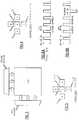
- FIG. 6A While satisfactory results are obtained with a single phase pulsed current, as shown in FIG. 6A, and denominated “Prior Art,” we have found that superior results are obtained with about 2.5 percent to about 25% voltage reversal with a two phase electroplating cycle, as shown in FIG. 6B.
- single phase pulsed electroplating cycle we mean an electroplating current that is pulsed to zero and positive values.
- two phase pulsed electroplating cycle we mean an electroplating current that is pulsed to zero and positive values and to zero and negative values, as shown in FIG. 6B.
- POSITIVE PULSE CONDITIONS Peak Current Density 200-400 Amperes/ft2 Pulse Time On 0.5 to 1.0 millisecond Pulse Time Off 2.0 to 9.0 milliseconds Duty Cycle 10% to 20% Positive Direction Time 20 to 40 seconds
- REVERSE PULSE CONDITIONS Peak Current Density 300 to 800 Amperes/ft2 Pulse Time On 0.5 to 1.0 millisecond Pulse Time Off 2.0 to 9.0 milliseconds Duty Cycle 10% to 20% Reverse Direction Time 1 to 5 seconds
- Gold, solder (as Pb-Sn or Bi-Sn) or even a thin overcoat of Pd may be applied atop the dendrites formed thereby.
- the resulting dendrites have a peak height of about 10 to 100 microns and a density (dendrites per unit area) of about 200 to 500 dendrites per square millimeter. Dendrites have a chip connect pad to dendritic pad contact resistance of about 3 to 5 milliohms.
- Conical connectors may also be utilized on the substrate or fixture.
- Conical connectors are described in the commonly assigned U.S. Patent 5,118,299 of Francis C. Burns, John J. Kaufman, David E. King, and Alan D. Knight, for CONE ELECTRICAL CONTACT, the disclosure of which is hereby incorporated herein by reference.
- Conical connectors are prepared by depositing an imagable polymeric material, as polyimide, and forming polymeric cones, as by laser ablation.
- the conical connectors are then coated, e.g., with a sputter chromium adhesion layer approximately 150 Angstroms thick, followed by sputter coating of a Cu layer approximately 10,000 to 100,000 Angstroms thick.
- a nickel coating approximately 0.1 to 1 mil thick is deposited atop the Cu, followed by a thin Au film.
- the integrated circuit chip is tested substantially as shown in Figure 2.
- the integrated circuit chip, with connectors on its substrate facing is positioned on the substrate or test fixture.
- the chip contacts or connectors on the chip bonding surface have deposited solder connectors, as solder balls or C4 (controlled collapse chip connectors) thereon for bonding to the substrate.
- the substrate or fixture has dendrites on the chip connect surfaces, contacts, or pads, substantially as described above.
- the chip and substrate are brought into contact and a compressive force is applied to the chip and substrate.
- the compressive force is sufficient to allow the dendrites to break through any oxide or corrosion films on the solder balls or C4 connectors on the chip.
- This provides direct, metal to metal contact, characterized by a contact resistance of less then 10 milliohms, and preferably less than 6 milliohms.
- the integrated circuit chip is powered, e.g., between inputs of V DD or V CC , and Ground, and subjected to various logic and memory tests. Chips that fail to pass these tests are discarded, while chips that pass these tests are installed in systems.
- the testing fixture is also the substrate, and chips that pass are bonded to the substrate between the bonding pad and the dendritic surface. Bonding may be by thermal compression bonding, transient liquid phase bonding, solder reflow, controlled collapse chip connect (C4 bonding) or the like. In the case of polymeric substrates bonding should take place below about 200 degrees Centigrade.
- the bond, or the bond, chip, and adjacent areas of substrate may be encapsulated in a suitable organic encapsulant.
- a suitable organic encapsulant for bonding the bond, or the bond, chip, and adjacent areas of substrate, may be encapsulated in a suitable organic encapsulant.
- coating or layer on the dendrites may be caused to fuse, bond, or alloy with the older balls or low melting materials on the integrated circuit chip to form an electrical or electrical and metallurgical bond.
- the integrated circuit chip may be tested for various defects while in dendritic contact with the dendritic surfaced pad. While the description herein is of the type of test procedures normally utilized for memory chips, especially CMOS memory chips, it is, of course, to be understood that the method of this invention is equally applicable to logic integrated circuit chips, and even to analog integrated circuit chips, as power processing chips and amplifier chips.
- the chip or chips may be tested for "cell stuck" faults.
- a "cell stuck at” fault one or more cells or gates are stuck-at-1 or stuck-at-0.
- a cell or gate When a cell or gate is stuck-at-x, it will remain stuck-at-x regardless of what is done to the cell or to surrounding cells or gates.
- Memory chips have a decoder.
- the decoder is the combinational circuit that selects a unique memory word corresponding to an address. Failures in decoder logic result in “no access faults” and in “multiple access faults.” In “no access faults” the decoder will not address the accessed cell. The decoder may address non-addressed cells. In “multiple access faults” the decoder will address multiple cells, possibly including the addressed cell.
- Pattern sensitive faults exist when cells are "coupled.” Cells are “coupled” when a transition at a cell, due to a write operation at this cell, changes the contents of a second cell, independently of the contents of the second cell or of any other cells. Coupling can be uni-directional, i.e., a change the state of cell i can change the state of cell j, but a change of the state of cell j does not change the state of cell i, or bi-directional, i.e., a change of the state of cell i changes the state of cell j, and a change of the state of cell j changes the state of cell i. Typically, pattern sensitive faults are identified with capacitive coupling and leakage currents.
- faults in access circuitry Another class of faults to which integrated circuit chips, especially memory chips, are susceptible to are faults in access circuitry. Accessing faults occur when more then one memory cell is accessed during a READ or WRITE operation. During a READ operation at some address, i,j, more then one cell can be accessed, and the output is some combinatorial function of the contents of both cells. During a write operation at one of the "coupled" addresses, all of the activated or accessed cells are written to simultaneously. Other types of accessing faults occur when the sense amplifier logic or the write driver logic are "stuck at X.” These faults may be due to capacitive coupling or due to shorts.
- a memory array, with column and row decoders is shown in Figure 3.
- a simplified RAM having a 8X4 memory array of 8 rows by 4 words per row.
- the routine shown below which requires 4 n tests (where n is the number of memory cells in the memory array) detects decoder faults and cell "stuck at" faults.
- March test pattern There are various procedures for generating the March test pattern. Specifically, one such procedure starts by classifying possible physical defects (shorts, opens, oxide too thin, etc.) likely to effect memory functionality or having a high probability of occurrence.
- the circuit is simulated by a circuit simulator, as SPICE or ASTAP.
- the purpose of this simulation is to determine the impact the effect of the physical defect on the memory. Defects can affect either memory functionality or memory performance.
- test patterns are then derived from the failure modes.
- the test patterns are derived to cover all of the failure modes identified for the memory.
- test patterns are then run against the simulator to insure that the test pattern detects defined failure modes.
- defects are memory cell defects that initially appear as a "Stuck-At-X" defect. However, sometimes a defective cell can drive the entire output of an entire row, or appear as a pattern sensitive fault.
- the March Test is particularly preferred for testing the decoder.
- the March Test tests for cell "stuck at" faults, and it tests for coupling faults.
- the March Test does not test for pattern sensitive faults. This is because the March test is linearly sequential, and can mask pattern sensitive faults.
- the March Test detects the following faults:
- An improved March Test Pattern that can be utilized with the structure and method of the invention is:
- Pattern Sensitive Faults can be passive or active.
- Passive pattern sensitive faults are faults such that a pattern of cell values prevents writing a value into a cell.
- a passive pattern sensitive fault pattern is shown in Figure 4.
- Active pattern sensitive faults occur when the change of value in one memory cell causes the value stored in another cell to change.
- the measured value of the contents of cell E we expect the measured value of the contents of cell E to be a function of the contents of the surrounding cells, and not necessarily the value set by the testing program.
- Testing for passive pattern sensitive faults requires ⁇ 65 n tests, where n is the number of cells.
- Testing for active pattern sensitive faults requires ⁇ 100 n tests, where n is the number of cells.
- test procedures may be applied to an integrated circuit chip in situ in the environment where it is to function in service, along with actual fan-out and latency effects. This is a particular advantage over existing test procedures.
Landscapes
- Engineering & Computer Science (AREA)
- Physics & Mathematics (AREA)
- General Physics & Mathematics (AREA)
- Computer Hardware Design (AREA)
- Microelectronics & Electronic Packaging (AREA)
- General Engineering & Computer Science (AREA)
- Environmental & Geological Engineering (AREA)
- Health & Medical Sciences (AREA)
- Toxicology (AREA)
- Testing Or Measuring Of Semiconductors Or The Like (AREA)
- Testing Of Individual Semiconductor Devices (AREA)
Applications Claiming Priority (2)
| Application Number | Priority Date | Filing Date | Title |
|---|---|---|---|
| US2454993A | 1993-03-01 | 1993-03-01 | |
| US24549 | 1993-03-01 |
Publications (2)
| Publication Number | Publication Date |
|---|---|
| EP0614089A2 true EP0614089A2 (de) | 1994-09-07 |
| EP0614089A3 EP0614089A3 (de) | 1995-07-12 |
Family
ID=21821176
Family Applications (1)
| Application Number | Title | Priority Date | Filing Date |
|---|---|---|---|
| EP94102896A Withdrawn EP0614089A3 (de) | 1993-03-01 | 1994-02-25 | Verfahren und Vorrichtung zum in situ Testen von Clips mit integrierten Schaltungen. |
Country Status (6)
| Country | Link |
|---|---|
| US (1) | US6414509B1 (de) |
| EP (1) | EP0614089A3 (de) |
| JP (1) | JP2528619B2 (de) |
| KR (1) | KR0130736B1 (de) |
| CA (1) | CA2110472C (de) |
| TW (1) | TW232090B (de) |
Cited By (7)
| Publication number | Priority date | Publication date | Assignee | Title |
|---|---|---|---|---|
| EP0792463A4 (de) * | 1994-11-15 | 1998-06-24 | Formfactor Inc | Montage von federelementen auf halbleiterbauteilen und wafertestverfahren |
| WO1999016130A1 (en) * | 1997-09-22 | 1999-04-01 | Cray Research, Inc. | Demountable, compliant area array interconnect |
| US6252175B1 (en) | 1993-11-16 | 2001-06-26 | Igor Y. Khandros | Electronic assembly comprising a substrate and a plurality of springable interconnection elements secured to terminals of the substrate |
| WO2002099845A3 (de) * | 2001-06-06 | 2003-08-21 | Infineon Technologies Ag | Elektronischer chip und elektronische chip-anordnung |
| US6956174B2 (en) | 1993-11-16 | 2005-10-18 | Formfactor, Inc. | Tip structures |
| EP1198001A3 (de) * | 1994-11-15 | 2008-07-23 | FormFactor, Inc. | Test- und Montage-Methode mittels Federkontaktstruktur |
| US9104568B2 (en) | 2013-03-15 | 2015-08-11 | International Business Machines Corporation | Detection of memory cells that are stuck in a physical state |
Families Citing this family (14)
| Publication number | Priority date | Publication date | Assignee | Title |
|---|---|---|---|---|
| US5829128A (en) | 1993-11-16 | 1998-11-03 | Formfactor, Inc. | Method of mounting resilient contact structures to semiconductor devices |
| US7200930B2 (en) | 1994-11-15 | 2007-04-10 | Formfactor, Inc. | Probe for semiconductor devices |
| US7084656B1 (en) | 1993-11-16 | 2006-08-01 | Formfactor, Inc. | Probe for semiconductor devices |
| US20100065963A1 (en) | 1995-05-26 | 2010-03-18 | Formfactor, Inc. | Method of wirebonding that utilizes a gas flow within a capillary from which a wire is played out |
| US7898275B1 (en) * | 1997-10-03 | 2011-03-01 | Texas Instruments Incorporated | Known good die using existing process infrastructure |
| JP3553791B2 (ja) | 1998-04-03 | 2004-08-11 | 株式会社ルネサステクノロジ | 接続装置およびその製造方法、検査装置並びに半導体素子の製造方法 |
| US6764869B2 (en) * | 2001-09-12 | 2004-07-20 | Formfactor, Inc. | Method of assembling and testing an electronics module |
| US6747472B2 (en) * | 2002-01-18 | 2004-06-08 | International Business Machines Corporation | Temporary device attach structure for test and burn in of microjoint interconnects and method for fabricating the same |
| US6836134B2 (en) * | 2002-06-11 | 2004-12-28 | Delphi Technologies, Inc. | Apparatus and method for determining leakage current between a first semiconductor region and a second semiconductor region to be formed therein |
| ATE452418T1 (de) * | 2006-09-12 | 2010-01-15 | Koninkl Philips Electronics Nv | Leuchte mit einem in die quarzglashülle der leuchte integrierten leiter |
| EA020950B1 (ru) | 2007-09-17 | 2015-03-31 | Баррик Гольд Корпорейшн | Способ усовершенствования восстановления золота из двойных тугоплавких золотосодержащих руд |
| US8262770B2 (en) | 2007-09-18 | 2012-09-11 | Barrick Gold Corporation | Process for controlling acid in sulfide pressure oxidation processes |
| US7922788B2 (en) | 2007-09-18 | 2011-04-12 | Barrick Gold Corporation | Process for recovering gold and silver from refractory ores |
| CN113990793A (zh) * | 2021-10-21 | 2022-01-28 | 东莞市中麒光电技术有限公司 | 一种led芯片转移方法 |
Family Cites Families (17)
| Publication number | Priority date | Publication date | Assignee | Title |
|---|---|---|---|---|
| US4189825A (en) * | 1975-06-04 | 1980-02-26 | Raytheon Company | Integrated test and assembly device |
| US4328286A (en) | 1979-04-26 | 1982-05-04 | The International Nickel Co., Inc. | Electrodeposited palladium, method of preparation and electrical contact made thereby |
| JPS57110690A (en) | 1980-12-24 | 1982-07-09 | Ibm | Growing of tentrite by electroplating |
| US4716124A (en) | 1984-06-04 | 1987-12-29 | General Electric Company | Tape automated manufacture of power semiconductor devices |
| US4820976A (en) | 1987-11-24 | 1989-04-11 | Advanced Micro Devices, Inc. | Test fixture capable of electrically testing an integrated circuit die having a planar array of contacts |
| DE68913823T2 (de) * | 1988-06-21 | 1994-09-22 | Ibm | Lösbare elektrische Verbindung. |
| US5137461A (en) * | 1988-06-21 | 1992-08-11 | International Business Machines Corporation | Separable electrical connection technology |
| US5007163A (en) * | 1990-04-18 | 1991-04-16 | International Business Machines Corporation | Non-destructure method of performing electrical burn-in testing of semiconductor chips |
| US5118299A (en) * | 1990-05-07 | 1992-06-02 | International Business Machines Corporation | Cone electrical contact |
| GB2247565B (en) * | 1990-08-22 | 1994-07-06 | Gen Electric Co Plc | A method of testing a semiconductor device |
| US5088190A (en) * | 1990-08-30 | 1992-02-18 | Texas Instruments Incorporated | Method of forming an apparatus for burn in testing of integrated circuit chip |
| US5237269A (en) * | 1991-03-27 | 1993-08-17 | International Business Machines Corporation | Connections between circuit chips and a temporary carrier for use in burn-in tests |
| US5523696A (en) * | 1993-06-14 | 1996-06-04 | International Business Machines Corp. | Method and apparatus for testing integrated circuit chips |
| US5420520A (en) * | 1993-06-11 | 1995-05-30 | International Business Machines Corporation | Method and apparatus for testing of integrated circuit chips |
| US5659256A (en) * | 1993-06-11 | 1997-08-19 | International Business Machines Corporation | Method and apparatus for testing integrated circuit chips |
| US5494856A (en) * | 1994-10-18 | 1996-02-27 | International Business Machines Corporation | Apparatus and method for creating detachable solder connections |
| US6037786A (en) * | 1996-12-13 | 2000-03-14 | International Business Machines Corporation | Testing integrated circuit chips |
-
1993
- 1993-12-01 CA CA002110472A patent/CA2110472C/en not_active Expired - Fee Related
-
1994
- 1994-02-07 JP JP6013281A patent/JP2528619B2/ja not_active Expired - Lifetime
- 1994-02-19 KR KR1019940003002A patent/KR0130736B1/ko not_active Expired - Fee Related
- 1994-02-25 EP EP94102896A patent/EP0614089A3/de not_active Withdrawn
- 1994-03-03 TW TW083101868A patent/TW232090B/zh active
-
2000
- 2000-05-03 US US09/564,652 patent/US6414509B1/en not_active Expired - Fee Related
Cited By (9)
| Publication number | Priority date | Publication date | Assignee | Title |
|---|---|---|---|---|
| US6252175B1 (en) | 1993-11-16 | 2001-06-26 | Igor Y. Khandros | Electronic assembly comprising a substrate and a plurality of springable interconnection elements secured to terminals of the substrate |
| US6956174B2 (en) | 1993-11-16 | 2005-10-18 | Formfactor, Inc. | Tip structures |
| EP0792463A4 (de) * | 1994-11-15 | 1998-06-24 | Formfactor Inc | Montage von federelementen auf halbleiterbauteilen und wafertestverfahren |
| EP1198001A3 (de) * | 1994-11-15 | 2008-07-23 | FormFactor, Inc. | Test- und Montage-Methode mittels Federkontaktstruktur |
| WO1999016130A1 (en) * | 1997-09-22 | 1999-04-01 | Cray Research, Inc. | Demountable, compliant area array interconnect |
| US6142789A (en) * | 1997-09-22 | 2000-11-07 | Silicon Graphics, Inc. | Demateable, compliant, area array interconnect |
| WO2002099845A3 (de) * | 2001-06-06 | 2003-08-21 | Infineon Technologies Ag | Elektronischer chip und elektronische chip-anordnung |
| US7301779B2 (en) | 2001-06-06 | 2007-11-27 | Infineon Technologies Ag | Electronic chip and electronic chip assembly |
| US9104568B2 (en) | 2013-03-15 | 2015-08-11 | International Business Machines Corporation | Detection of memory cells that are stuck in a physical state |
Also Published As
| Publication number | Publication date |
|---|---|
| CA2110472A1 (en) | 1994-09-02 |
| JPH06252226A (ja) | 1994-09-09 |
| TW232090B (de) | 1994-10-11 |
| US6414509B1 (en) | 2002-07-02 |
| KR940022769A (ko) | 1994-10-21 |
| JP2528619B2 (ja) | 1996-08-28 |
| EP0614089A3 (de) | 1995-07-12 |
| CA2110472C (en) | 1999-08-10 |
| KR0130736B1 (ko) | 1998-04-06 |
Similar Documents
| Publication | Publication Date | Title |
|---|---|---|
| US5420520A (en) | Method and apparatus for testing of integrated circuit chips | |
| CA2110472C (en) | Method and apparatus for in-situ testing of integrated circuit chips | |
| US6118138A (en) | Reduced terminal testing system | |
| US6233184B1 (en) | Structures for wafer level test and burn-in | |
| US5007163A (en) | Non-destructure method of performing electrical burn-in testing of semiconductor chips | |
| US5570032A (en) | Wafer scale burn-in apparatus and process | |
| US5659256A (en) | Method and apparatus for testing integrated circuit chips | |
| US20070046313A1 (en) | Mounting Spring Elements on Semiconductor Devices, and Wafer-Level Testing Methodology | |
| US5686843A (en) | Methods and apparatus for burn-in stressing and simultaneous testing of semiconductor device chips in a multichip module | |
| US5239199A (en) | Vertical lead-on-chip package | |
| EP0802418A2 (de) | Verfahren zur Hochgeschwindigkeitsprüfung eines Halbleitergeräts | |
| US5239747A (en) | Method of forming integrated circuit devices | |
| US5461544A (en) | Structure and method for connecting leads from multiple chips | |
| JP3522426B2 (ja) | プローブ試験用の電源パッドを有する半導体チップ及び半導体ウエハ | |
| EP0495629A1 (de) | Chipgehäuse mit Vertikalanschlüssen | |
| US20060261836A1 (en) | Method and system for stressing semiconductor wafers during burn-in | |
| DE69723976T2 (de) | Einbrennen und testen eines halbleiterwafers | |
| JPH04106959A (ja) | 多面付チップキャリア基板のプッシュバック工法 | |
| Quinn et al. | New Process for Automated IC Assembly Manufacturing | |
| JPS63114246A (ja) | 半導体装置 | |
| JPH04312943A (ja) | 半導体チップの実装方法 | |
| JPH07118495B2 (ja) | フィルムキャリアテープ | |
| JPS60226140A (ja) | 半導体集積回路装置 |
Legal Events
| Date | Code | Title | Description |
|---|---|---|---|
| PUAI | Public reference made under article 153(3) epc to a published international application that has entered the european phase |
Free format text: ORIGINAL CODE: 0009012 |
|
| AK | Designated contracting states |
Kind code of ref document: A2 Designated state(s): AT BE CH DE ES FR GB IT LI NL SE |
|
| 17P | Request for examination filed |
Effective date: 19950117 |
|
| PUAL | Search report despatched |
Free format text: ORIGINAL CODE: 0009013 |
|
| AK | Designated contracting states |
Kind code of ref document: A3 Designated state(s): AT BE CH DE ES FR GB IT LI NL SE |
|
| 17Q | First examination report despatched |
Effective date: 20000203 |
|
| STAA | Information on the status of an ep patent application or granted ep patent |
Free format text: STATUS: THE APPLICATION IS DEEMED TO BE WITHDRAWN |
|
| 18D | Application deemed to be withdrawn |
Effective date: 20000614 |