EP0614154A2 - Verfahren und Vorrichtung zur Verbesserung von Mehrtonbildern - Google Patents
Verfahren und Vorrichtung zur Verbesserung von Mehrtonbildern Download PDFInfo
- Publication number
- EP0614154A2 EP0614154A2 EP94103065A EP94103065A EP0614154A2 EP 0614154 A2 EP0614154 A2 EP 0614154A2 EP 94103065 A EP94103065 A EP 94103065A EP 94103065 A EP94103065 A EP 94103065A EP 0614154 A2 EP0614154 A2 EP 0614154A2
- Authority
- EP
- European Patent Office
- Prior art keywords
- image data
- data
- tone image
- contour
- vector
- Prior art date
- Legal status (The legal status is an assumption and is not a legal conclusion. Google has not performed a legal analysis and makes no representation as to the accuracy of the status listed.)
- Withdrawn
Links
Images

















Classifications
-
- G—PHYSICS
- G06—COMPUTING OR CALCULATING; COUNTING
- G06T—IMAGE DATA PROCESSING OR GENERATION, IN GENERAL
- G06T5/00—Image enhancement or restoration
- G06T5/77—Retouching; Inpainting; Scratch removal
-
- G—PHYSICS
- G06—COMPUTING OR CALCULATING; COUNTING
- G06T—IMAGE DATA PROCESSING OR GENERATION, IN GENERAL
- G06T5/00—Image enhancement or restoration
- G06T5/20—Image enhancement or restoration using local operators
- G06T5/30—Erosion or dilatation, e.g. thinning
-
- H—ELECTRICITY
- H04—ELECTRIC COMMUNICATION TECHNIQUE
- H04N—PICTORIAL COMMUNICATION, e.g. TELEVISION
- H04N1/00—Scanning, transmission or reproduction of documents or the like, e.g. facsimile transmission; Details thereof
- H04N1/40—Picture signal circuits
- H04N1/409—Edge or detail enhancement; Noise or error suppression
- H04N1/4097—Removing errors due external factors, e.g. dust, scratches
-
- G—PHYSICS
- G06—COMPUTING OR CALCULATING; COUNTING
- G06T—IMAGE DATA PROCESSING OR GENERATION, IN GENERAL
- G06T2207/00—Indexing scheme for image analysis or image enhancement
- G06T2207/10—Image acquisition modality
- G06T2207/10004—Still image; Photographic image
- G06T2207/10008—Still image; Photographic image from scanner, fax or copier
Definitions
- the present invention relates to a method and apparatus for correcting a multi-tone image.
- an original Image such as a color photograph is scanned by a color scanner to produce image data.
- the image captured by a scanner often includes defects due to rubbing-off blemishes and dust on the original, electric noise, and stains in an optical system.
- an operator checks a multi-tone image displayed on a CRT, and if a detect is found, pixel density data in a normal image area is copied to the defective area to eliminate the defect.
- a colored image shown on a display can be electronically retouched with a light pen.
- a multi-tone image may be corrected by copying image data of a normal image area to a target image area requiring correction.
- the correction process is highly time-consuming because it requires an operator to specify a position of each pixel to be corrected and a position of an image area to be copied at the position of the pixel,
- An object of the present invention is to provide a novel method and an apparatus for readily correcting a multi-tone image.
- the present invention is directed to an apparatus for correcting a multi-tone image.
- the apparatus comprises: a first memory for storing first multi-tone image data representing image density for every pixel in the multi-tone image; binarization means for comparing the first multi-tone image data with each of a plurality of threshold values to thereby produce a plurality of first binary image data representing a plurality of binary images; a second memory for storing the plurality of first binary image data; contour correction means for correcting a contour of each of the plurality of binary images by executing contraction and expansion on each of the plurality of first binary image data, to thereby produce a plurality of second binary image data; and restoration means for re-converting the plurality of second binary image data to second multi-tone age data representing a corrected multi-tone image.
- a plurality of first binary image data generated by the binarization means represent contours of a plurality of density levels in an original multi-tone image, and contraction and expansion on the plurality of first binary image data reduces unevenness or irregularities of the contours.
- the second multi-tone image obtained by the restoration means represent corrected contours consequently.
- a contraction width in the contraction is equal to an expansion width in the expansion.
- the apparatus further comprises: specification means for specifying a mask area to be corrected in the multi-tone image; and data correction means for extracting an image data segment representing the mask area of the corrected multi-tone image from the second multi-tone image data, and replacing a corresponding data segment of the first multi-tone image data with the image data segment to produce third multi-tone image data representing a corrected multi-tone image.
- the contraction width is at least half of a width of the mask area.
- the apparatus further comprises: means for changing a data value of the first multi-tone image in the mask area to a predetermined value.
- the predetermined value represents one of a white area and a black area.
- the restoration means comprises: means for adding the plurality of second binary image data with respect to each pixel to thereby produce the second multi-tone image data.
- the restoration means comprises: means for replacing a data value of one in each of the plurality of second binary image data by respective one of the plurality of threshold values, which is used in producing respective one of the plurality of first binary image data, to produce a plurality of intermediate image data, and over-writing the plurality of intermediate image data one after another in order of the plurality of threshold values to thereby produce the second multi-tone image data.
- the present invention is also directed to an apparatus for correcting a multi-tone image comprising: first memory for storing first multi-tone image data representing image density for every pixel in the multi-tone image; binarization means for comparing the first multi-tone image data with each of a plurality of threshold values to thereby produce a plurality of binary image data representing a plurality of binary images; a second memory for storing the plurality of binary image data; contour extraction means for converting the plurality of binary image data to a plurality of first contour vector data each of which represents a contour of the plurality of binary images; contour correction means for correcting a contour of each of the plurality of binary images by executing contraction and expansion on each of the plurality of first contour vector data, to thereby produce a plurality of second contour vector data; and restoration means for reconverting the plurality of second contour vector data to second multi-tone image data representing a corrected multi-tone image.
- the contour correction means can execute contraction and expansion of the contour vector data in a relatively high speed to reduce unevenness or irregularities of the contours.
- the restoration means comprises: means for assigning respective one of the plurality of threshold values, which is used in producing respective one of the plurality of first binary image data, to every pixel in an area at a predetermined side of the contour represented by each of the plurality of second contour vector data to thereby produce a plurality of intermediate image data, and over-writing the plurality of intermediate image data one after another in order of the plurality of threshold values to thereby produce the second multi-tone image data.
- the present invention is further directed to a method of correcting a multi-tone image comprising the steps of: (a) providing first multi-tone image data representing image density for every pixel in the multi-tone image; (b) comparing the first multi-tone image data with each of a plurality of threshold values to thereby produce a plurality of first binary image data representing a plurality of binary images; (c) correcting a contour of each of the plurality of binary images by executing contraction and expansion on each of the plurality of first binary image data, to thereby produce a plurality of second binary image data; and (d) re-converting the plurality of second binary image data to second multi-tone image data representing a corrected multi-tone image.
- the present invention is still further directed to a method of correcting a multi-tone image comprising the steps of: (a) providing first multi-tone image data representing image density for every pixel in the multi-tone image; (b) comparing the first multi-tone image data with each of a plurality of threshold values to thereby produce a plurality of binary image data representing a plurality of binary images; (c) converting the plurality of binary image data to a plurality of first contour vector data each of which represents a contour of the plurality of binary images; (d) correcting a contour of each of the plurality of binary images by executing contraction and expansion on each of the plurality of first contour vector data, to thereby produce a plurality of second contour vector data; and (e) re-converting the plurality of second contour vector data to second multi-tone image data representing a corrected multi-tone image.
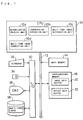
- Fig. 1 is a block diagram showing an image processing system as a first embodiment of the present invention.
- the image processing system includes a CPU 10 and a bus line 12 which is connected to a main memory 14 and an supplementary memory unit 16.
- the bus line 12 is also connected to a keyboard 33, a mouse 34, a color CRT 36, and a magnetic disk unit 38 via an input/output interface 30.
- the magnetic disk unit 38 stores multi-tone image data.
- the supplementary memory unit 16 corresponds to the first memory means and the second memory means of the claimed invention while the mouse 34 works as the specification means.
- the CPU 10 executes software programs stored in the main memory 14 to implement a binarization process unit 10a, a contraction-expansion unit 10b, a multi-tone image restoration unit 10c, and a multi-tone image correction unit 10d, which respectively correspond to the data conversion means, the contour correction means, the restoration means, and the data correction means of the claimed invention.
- These units 10a, 10b, 10c, and 10d can be also implemented by hardwares alternatively.
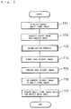
- Fig. 2 is a flowchart showing the general procedure of the first embodiment.
- an operator specifies a target multi-tone image (hereinafter referred to as "original image"), which is then displayed on the color CRT 36.
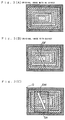
- Figs. 3(A) through 3(C) are plan views showing exemplified original images displayed on the color CRT 36.
- An original image shown in Fig. 3(A) is free of any defect whereas that shown in Fig. 3(B) has a blemish or defect DF.
- each original image represents a colored image
- multi-tone image data corresponding to the original image includes luminance data of three primary colors R (red), G (green), and B (blue).
- the program proceeds to step TT2 at which the operator specifies a defect mask DM and a process area SA shown in Fig. 3(C) with the mouse 34.
- the defect mask DM defines a small area including the defect DF, for examples, a rectangular area, while the process area SA is a larger rectangular area including the defect mask DM.
- Multi-tone image data representing the process area SA are extracted from the original image data and stored in an image data buffer 20 of the supplementary memory unit 16 (Fig. 1). Inside the defect mask DM is painted in white (or black) in the image data buffer 20.
- the luminance of each color in the defect mask DM is set equal to 255 indicating white, or 0 indicating black.
- Coordinates showing contour points of the defect mask DM which are determined with regard to an origin O of the multi-tone image, are stored in a defect data buffer 22 of the supplementary memory unit 16 (Fig. 1).
- the defect mask DM corresponds to the target area of the claimed invention
- the defect mask DM may have any shape so that it includes the defect DF.
- the process area SA is specified by the operator in this embodiment, it can be determined automatically to include the defect mask DM; for example, a rectangular area circumscribing the defect mask DM can be used as the process area SA.
- the binarization process unit 10a converts non-processed multi-tone image data of the process area SA to binary data.
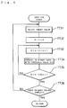
- Fig. 4 is a flowchart showing details of the binarization process executed at step TT3.
- the binarization process unit 10a selects a target color out of the three primary colors R, G, and B.
- the binarization process unit 10a initializes a binarization threshold value Dth to zero at step TT32 and increments the threshold value Dth by one at step TT33.
- the binarization process unit 10a converts non-processed multi-tone image data to binary image data by comparing the non-processed multi-tone image data with the threshold value Dth.
- the value of the binary image data is set equal to zero (representing black) for those pixels whose image data value is smaller than the threshold value Dth.
- the value of the binary image data is set equal to one (representing white) for those pixels whose image data vale is no less than the threshold value Dth.
- the threshold value Dth is compared with a predetermined maximum value Dmax which shows the upper limit of image data (255 in 8-bit data).
- a predetermined maximum value Dmax which shows the upper limit of image data (255 in 8-bit data).
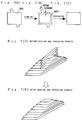
- Figs. 5(A) through 5(C) show results of the binarization process.
- Fig. 5(A) shows a multi-tone image in the process area SA
- Fig. 5(B) is a plan view showing a pile of binary images obtained through the binarization process.
- Fig. 5(C) is a perspective view showing the pile of binary images of Fig. 5(B) from the direction of the arrow C.
- values of multi-tone image data Di are limited within a range between 1 and 9 in the process area SA. Since the multi-tone image data represents the luminance in this embodiment, the higher the data value is, the brighter the area becomes.
- the multi-tone image data Di is equal to 9, or the maximum value, in the white defect mask area.
- Nine different binary images as shown in Figs. 6(A) through 6(I) are obtained by binarizing the multi-tone image data of Fig. 5(A) while varying the threshold value Dth from 1 to 9.
- the pile of binary images shown in Figs. 5(B) and 5(C) is obtained by overlaying the white areas of these binary images.
- the white areas represent the areas whose binary image data Dp is equal to 1 whereas the shaded areas show the areas whose binary image data Dp is equal to 0.
- the shape of the defect mask DM is observed in the seven binary images shown in Figs. 6(A) through 6G.
- Binary image data representing these nine binary images are stored in the image data buffer 20 of the supplementary memory unit 16. When the supplementary memory unit 16 does not have a sufficient capacity, the binary image data can be stored temporarily in the magnetic disk unit 38.
- step TT36 (Fig. 4), it is determined whether the binarization process is completed for all of the three primary colors R, G, and B. When the answer is NO at step TT36, the program returns to step TT31 to repeat the binarization process for a next color.
- each binary image is contracted or choked at step TT4 ((Fig. 2) and expanded or spread at step TT5 so as to eliminate the defect DF.
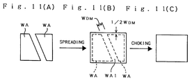
- Figs. 7(A) through 7(E) show a process of choking and spreading the binary image.
- Fig. 7(A) shows a contour of a white area WA of the binary image shown in Fig. 6(E).
- the white area WA of Fig. 7(A) is contracted to make a white area WA1 shown in Fig. 7(B), which does not show the shape of the defect mask DM.
- the choking process is executed to eliminate the shape of the defect mask DM, and therefore the white area WA is contracted by a predetermined choking width no less than half a width WDM of the defect mask DM.
- the width WDM of the defect mask DM is determined according to the coordinates of the vertices of the defect mask DM stored in the defect data buffer 22 of the supplementary memory unit 16.
- the choked white area WA1 is spread by a predetermined spread width which is equal to the choking width, thereby generating a binary image showing nothing indicative of the defect mask DM as shown in Fig. 7(C).
- the choking and spreading process can be executed using an 8-neighbor window, which is well known in the the field of image processing. Choking of the white area WA is equivalent to spreading of a black area, and spreading of the white area WA is equivalent to choking of the black area.
- Fig. 7(E) includes eight binary images.
- Fig. 8(A) is a p;an view of the pile of the eight binary images, where only seven areas can be seen because the two binary images at the bottom, which correspond to those shown in Figs. 6(H) and 6(I), have the same shape.
- step TT6 the multi-tone image restoration unit 10c re-converts the binary images to a multi-tone image. Since the value of the binary image data Dp is equal to one in the white areas of the eight binary images as shown in Fig. 8A, the re-converted multi-tone image data Di shown in Fig. 8(B) are obtained by simply adding the binary Image data Dp of the eight binary images with respect to each pixel.
- the multi-tone image correction unit 10d extracts a data segment representing the area conforming to the defect mask DM (Fig. 9(A)) from the resultant multi-tone image data Di of the defect-free multi-tone image shown in Fig. 8(B), and replaces the corresponding data segment of the original multi-tone image data of the original image with the extracted data segment.
- the range of the defect mask DM is determined according to the coordinates of the contour points of the defect mask DM shown in Fig.
- the original image is corrected through processing of binary image data.
- the original image is corrected through processing of contour vector data which is converted from binary image data to represent the contour of the image.
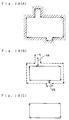
- Figs. 12(a) through 12(c) show the comparison between A pixel-centered contour and A pixel-boundary contour in a monochrome image.
- a pixel-centered contour is constituted by vectors whose end points are defined by pixel coordinates Xp, Yp as shown in Fig. 12(a).
- the contour vector of the pixel-centered contour passes through the centers of pixels.
- a pixel-boundary contour is constituted by vectors whose end points are defined by boundary coordinates (coordinates of the boundary between pixels) Xb, Yb as shown in Fig. 12(b).
- the contour vectors of the pixel-boundary contour runs along the outer boundary of pixels.
- Fig. 13 is a block diagram showing an image processing system as the second embodiment of the present invention.
- the image processing system has a structure similar to that shown in Fig. 1 except the following points: the CPU 10 includes a run data conversion unit 10e and a contour extracting unit 10f other than the units 10a through 10d; the supplementary memory 16 includes a contour extraction data buffer 24 and a restoration data buffer 26 other than the image data buffer 20 and the defect data buffer 22.
- the run data conversion unit 10e and the contour extracting unit 10f correspond to the contour extraction means of the claimed invention.
- the run data conversion unit 10e converts binary image data to run data.
- the run data indicates edges of the binary image along a scanning direction by the pixel-boundary coordinates at the edges. A method of converting binary image data to run data will be described later.
- the contour extracting unit 10f processes the run data to detect contour points, to generate segment vectors representing segments of the contour, and to detect a closed loop formed by linking the segment vectors to one another. Details of the processing will be described later in detail.
- the contour extraction data buffer 24 stores working data used in conversion of binary image data to contour vector data by the run data conversion unit 10e and the contour extracting unit 10f.
- the restoration data buffer 26 stores working data used in restoration of contour vector data to produce multi-tone image data by the multi-tone image restoration unit 10c.
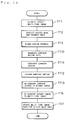
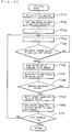
- Fig. 14 is a flowchart showing the procedure of contour correction process executed in the second embodiment. Steps TT1 through TT3 in Fig. 14 are identical with those shown in Fig. 2. After completion of these steps TT1 through TT3, for example, nine binary image data are obtained as shown in Figs. 6(A) through 6(I).
- the run data conversion unit 10e and the contour extracting unit 10f generate contour vector data from the binary image data.
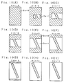
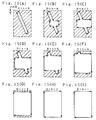
- Figs. 15(A) through 15(I) show contour vectors of the binary images of Figs. 6(A) through 6(I).
- the contour vector data represents a vector sequence indicative of a contour of a white area of each binary image, which binary image data Dp is equal to one as shown in Figs. 6(A) through 6(I). This is because white areas are subject to contraction and expansion in this embodiment.
- the contour vector sequences includes only "boundary vectors" which run along pixel boundaries and which are parallel to either a primary scanning direction Y or a secondary scanning direction X. In Fig. 15, however, contour vector sequences are drawn to include oblique vectors for convenience of illustration. Details of the process of generating contour vector data will be described later in detail.
- each of the nine contour vector sequences is contracted.
- Figs. 16(A1) through 16(A5) and 16(B1) through 16(B5) show typical processes of contracting contour vector sequences.
- the vectors before the contracting process are drawn with broken lines whereas the contracted vectors are drawn with solid lines.
- a black area filled with slant lines is located on the left side of each vector sequence while a white area is located on the right side thereof in this embodiment.
- Figs. 16 (A1) through 16(A4) two adjacent vectors V1 and V2 turn clockwise, or turn right along the course of the vector sequence.
- an intermediate point Pm of the two vectors V1 and V2 shown by an open circle moves in a lower right direction with respect to the course of the vector sequence.
- a white area defined by four vectors V1 through V4 is contracted as shown in Fig. 16 (A5).
- Figs. 16(B1) through 16(B4) two adjacent vectors V1 and V2 turn counterclockwise, or turn left along the course of the vector sequence.
- an intermediate point Pm of the two vectors V1 and V2 moves in an upper right direction with respect to the course of the vector sequence.
- a black area defined by four vectors V1 through V4 is expanded as shown in Fig. 16(B5).
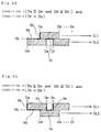
- coordinates of the intermediate point Pm after the contracting movement can be determined according to the following method. Since a contour vector sequence represents a boundary contour, each vector is in parallel with either of the coordinate axes of the boundary coordinates (X, Yb). A starting point and an end point of a certain vector have the same value for one of the boundary coordinates Xb and Yb, and different values for the other boundary coordinate. In the example of Fig.
- the starting point and the end point of the first vector V1 have the same value in the Xb coordinate and different values in the Yb coordinate while the starting point and the end point of the second vector V2 have the same value in the Yb coordinate and different values in the Xb coordinate.
- the turning direction of two adjacent vectors V1 and V2 can be determined by examining which coordinate goes up or down from the starting point to the end point with respect to each of the two vectors V1 and V2.
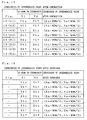
- Fig. 17 shows relations between the up-down in the coordinate values from the starting point to the end point with respect to two adjacent vectors V1 and V2 and corrected coordinates of intermediate points Pm (Xm,Ym) after the contracting movement in the examples of Figs.
- WDM represents a width of the defect mask.
- a contour vector sequence can be contracted by a desired width (WDM/2 in this embodiment) through one cycle of the contraction process.
- Figs. 18(A) through 18(C) show a process of contracting a contour vector sequence shown in Fig. 15 (E), where the shape of the contour is further simplified for convenience of explanation.
- Fig. 18(A) shows a contour vector before the contraction process
- Fig. 18(B) shows a state after movement of intermediate points according to the method shown in Figs. 16 (A1) through 16 (A5) and 16(B1) through 16(B5)
- Fig. 18(C) shows a resultant contour after the contraction process.
- vectors running in opposite directions overlap each other at two parts VA and VB. These overlapped vectors VA and VB are cancelled out, and a contour vector sequence having no overlapping is generated as shown in Fig. 18(C).
- the contracted contour vector sequence is expanded back at step TT12.
- intermediate points are moved in directions opposite to those in the contraction process shown in Fig. 17.
- step TT13 the multi-tone image restoration unit 10c restores a binary image from the corrected contour vector sequence. Details of this restoration process will be described later in detail.
- the program goes to step TT6 and then to step TT7 described before, thereby generating a final multi-tone image with no defect in the same manner as in the first embodiment.
- each binary image is converted to a contour vector sequence, and the contour vector sequence is contracted and expanded to eliminate defects in the image. Since vectors can be contracted and expanded by a desired width through only one cycle of the contraction routine and the expansion routine, respectively, the contraction and expansion process can be executed quickly.
- Fig. 20 is a flowchart showing details of the restoration process executed at step TT13 of Fig. 14.
- step TT41 all buffers used in the restoration process are initialized.
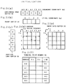
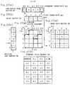
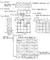
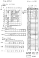
- Figs. 21(a) through 21(f) show the buffers initialized at step TT41 and a contour vector sequence to be processed in the restoration process.
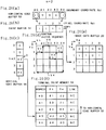
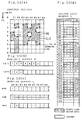
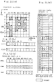
- the buffers used in the restoration process include a horizontal edge buffer 52, a paint buffer 54, a vertical sort buffer 56, and a terminal point memory 58. These buffers are assigned in specific areas of the restoration data buffer 26 (Fig. 13) in the supplementary memory unit 16.
- the horizontal edge buffer 52 stores boundary coordinates of black/white edges in a horizontal direction along the Xb axis.
- the paint buffer 54 temporarily stores binary image data obtained for one horizontal scanning line.
- the vertical sort buffer 56 is used for sorting horizontal vectors in a vertical direction.
- the terminal point memory 58 stores a starting point coordinate Xs and an end point coordinate Xe for horizontal vectors sorted in the vertical direction. Binary image data obtained through the restoration process are stored in the image data buffer 20.
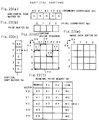
- Figs. 22(a) through 22(f) shows the sorting of horizontal vectors in the vertical direction.
- horizontal vectors V0 through V4 which are drawn with thick solid lines in Fig. 22(d)
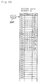
- Link data in the terminal point memory 58 (referred to as 'link' in the drawings) shows a linkage with another address, where 'NC' shows no connection with another address.
- a parameter n representing a position in the vertical sort buffer 56, or the value of the boundary coordinate Yb is initialized to -1.
- the parameter n is incremented by one.
- horizontal vectors along one horizontal scanning line are converted to binary images.
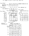
- step TT48 it is determined whether link data is registered for the currently processed vector in the terminal point memory 58; in other words, whether another horizontal vector is linked with the horizontal vector currently processed. When another horizontal vector is linked with the currently processed vector, steps TT46 and TT47 are repeated for the linked vector. In the example of Fig. 24(f), link data at the address *0 is 'NC', which indicates no horizontal vector linked.
- step TT49 binary image data are written in the paint buffer 54 according to the data in the horizontal edge buffer 52.
- the binary image data is set equal to one for pixels in a range between the boundary coordinate having a value '+1' and the boundary coordinate having a value '-1' in the horizontal edge buffer 52.
- step TT50 the binary image data in the paint buffer 54 are copied into the image data buffer 20 while the data in the vertical sort buffer 56 at the position indicated by the parameter n is initialized to zero as shown in Fig. 24(c).
- step TT51 it is determined whether this restoration process is completed for the last scanning line in the original image. when the answer is NO, the program returns to step TT44 to repeat the processing at steps TT44 through TT50.
- the terminal memory 58 is referred to at the address *2 accordingly, and the starting coordinates Xs and the end coordinate Xe of a horizontal vector registered at the address *2 are read out of the terminal point memory 58 (step TT46).
- steps TT46 and TT47 are executed for a linked horizontal vector registered at the address *1 in the terminal memory 58.
- steps TT46 and TT47 are executed for a linked horizontal vector registered at the address *1 in the terminal memory 58.
- steps TT46 and TT47 are executed for a linked horizontal vector registered at the address *1 in the terminal memory 58.
- steps TT46 and TT47 are executed for a linked horizontal vector registered at the address *1 in the terminal memory 58.
- steps TT46 and TT47 Through execution of steps TT46 and TT47, '+1' is added to the position of the coordinate #0 in the horizontal edge buffer 52 and '-1' is added to the position of the coordinate #1.
- Binary image data are written in the paint buffer 54 according to the data of the horizontal edge buffer 52 (step TT49). Namely, the binary image data is set equal to '1' for pixels in a range between the boundary coordinate having a value '+1' and the boundary coordinate having a value '-1' in the horizontal edge buffer 52.
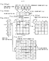
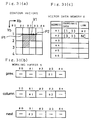
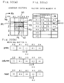
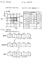
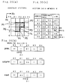
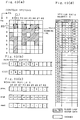
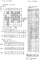
- Figs. 26(a) through 26(f), 27(a) through 27(f), and 28(a) through 28(f) show processing when the parameter n is equal to 2, 3, and 4, respectively.
- the parameter n is equal to 3 (Figs. 27(a) through 27(f))
- binary image data are written in the paint buffer 54 according to the data previously registered in the horizontal edge buffer 52 and are then copied into the image data buffer 20 as shown in Fig. 27(e).
- Fig. 29 is a block diagram showing a system structure concerning contour extraction.
- the run data conversion unit 10e, the contour extracting unit 10f, the image data buffer 20, and the contour extraction data buffer 24, all of which are shown in Fig. 13, are used for contour extraction.
- the contour extraction data buffer 24 includes a run data buffer unit 3, a working buffer unit 5, and a vector data memory 6.
- the run data buffer unit 3 temporarily stores run data generated in the run data conversion unit 10e and includes a first run data buffer 31 for storing run data of a previous scanning line and a second run data buffer 32 for storing run data of a current scanning line.
- the working buffer unit 5 temporarily stores data used in the contour extraction process and includes first through third registers, which are referred to as "prev. register 5p", “column register 5c”, and “next register 5n". Details of these registers 5c, 5p, and 5n will be described later in detail.
- the vector data memory 6 stores coordinate data of contour vector data and link pointers representing linkage of the coordinate data.
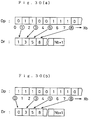
- Figs. 30(a) and 30(b) schematically illustrate a method of converting binary image data Dp into run-data Dr by the run-data conversion unit 10e.
- Each of Figs. 30(a) and 30(b) shows a binary image data Dp, and run-data Dr obtained by converting the binary image data Dp.
- Fig. 30(a) is an example where the first value of the binary image data Dp on a scanning line is zero while it is one in Fig. 30(b).
- the run-data Dr includes a sequence of the boundary coordinates Xb at which the value of the image data Dp changes.
- the maximum value Nb of the boundary coordinate Xb plus one, or Nb+1, which is equal to the number of pixels on the scanning line plus one is repeated three times as end data representing the end of the scanning line.
- the end data (Nb+1) accordingly defines the end of the run-data Dr for the given scanning line.
- Figs. 31(a) through 35(c) illustrate the linkage process subsequent to detection of each contour vector.
- the linkage process denotes updating the linkage of contour vectors, or more concretely registering specific data representing start point and end point of each contour vector in the working buffer 5 and the vector data memory 6.
- the contour extraction unit 10f executes this linkage process.
- 'column [#Xb]' denotes the position of the boundary coordinate Xb in the column-register 5c or the data registered at that position
- 'prev[#Xb]' and 'next [#Xb]' have the similar meanings.
- Fig. 31(a) shows a detected contour vector V1.
- the boundary coordinates (Xb,Yb) of a start point P1 and an end point P2 of the vector V1 are respectively stored at addresses *1 and *2 in the vector data memory 6.
- Link data at each address of the vector data memory 6 indicates the address of another coordinate data which is linked with the coordinate data stored at each respective address.
- the link data indicates the address at which the coordinate data of the end point of the vector is stored.
- the coordinate data (1,1) of the start point P1 of the vector V1 is stored at address *1
- the link data at address *1 shows address *2 where the coordinate data (3,1) of the end point P2 is stored.
- the link data 'NC' stored at the address *2 indicates that there is no other address linked to address *2.
- the three registers of the working buffer 5 can store one data for each boundary coordinate Xb.
- Functions of the three registers are as follows:
- the column-register 5c stores the address of the vector data memory 6 at which the coordinate data of the starting point of a vector sequence, or a series of linked vectors, is memorized, at the position corresponding to the boundary coordinate Xb of the starting point.
- the address of the memory 6 for the coordinate data of the terminal point of the vector sequence is stored at the position corresponding to the boundary coordinate Xb of the terminal point.
- the address *1 of the vector data memory 6, at which the coordinate data (1,1) of the start point P1 is registered, is written at column[#1] corresponding to the boundary coordinate Xb #1 of the start point P1 of the detected vector V1.
- the address of the vector data memory 6 will be hereinafter referred to as "address of the coordinate data.”
- the symbol '-' in the register shows that no valid data is registered there.
- the previous-register 5p stores the value of the boundary coordinate Xb of the starting point of the vector sequence at the position corresponding to the boundary coordinate Xb of the terminal point of the vector sequence.
- the next-register 5n stores the value of the boundary coordinate Xb of the terminal point of the vector sequence at the position of the boundary coordinate Xb of the starting point of the vector sequence.
- Figs. 32(a) through 32(c) show linkage process when another vector V2 is detected subsequent to the first vector V1.
- the contour extraction unit 10f detects the vectors which extend along the axis of the boundary coordinate Xb or in the primary scanning direction, as a function of the run-data.
- the vector V2 is detected after the vector V1 accordingly.
- specific data relating to the vector V2 is stored in the vector data memory 6 and the working buffer 5.
- Another vector V3 which extends along the boundary coordinate Yb or in the secondary scanning direction is detected as a function of the data for the vectors V1 and V2.
- steps (1) through (11) explain the registration of the specific data relating to the vector V2, the detection of the vector V3, and the registration of specific data concerned with the vector V3.
- Some of the symbols "(1)” through “(11)” indicating the following steps (1) through (11) are shown in the Figs. 32(a) through 9(c) for further explanation.
- the arrows in those figures show either that one data is changed to the other data or that the data is used to point out some position.
- the contour extraction unit 10f can register specific data of a starting point and a terminal point of a new vector sequence and update the linkage of the points in the vector sequence. Furthermore, when the vector sequence forms a closed-loop, the contour extracting unit 10f can detect the closed-loop without delay. As described above in detail, the contour extracting apparatus detects vectors at each scanning line by processing run-data while outputting contour vector data of a closed- loop vector sequence to external devices immediately after the detection of the closed-loop. In other words, the contour extracting apparatus can detect a contour of an image area without processing image data for all the scanning lines of the image, but by processing image data for one scanning line after another.
- Figs. 36 and 37 are flowcharts showing the details of the linkage process of the vectors explained along with Figs. 31(a) through 35(c).
- step SS0 X coordinate data Xs of a start point of a vector detected by the contour extraction unit 10f is compared with X coordinate data Xe of an end point of the vector.
- the program proceeds to step SS1 when Xs is not equal to Xe. Whereas the program quits the linkage process routine when Xs is equal to Xe. This is because no change is required in the current linkage state of the vector sequence when the X coordinate data Xs of the start point is equal to the X coordinate data Xe of the end point.
- the step SS0 effectively prevents conflict between linkage data in the registers of the working buffer 5.
- step SS1 coordinate data (Xs, Ys) of the start point and the same (Xe, Ye) of the end point for the detected vector are stored in the vector data memory 6. No link data has been registered yet at this stage.
- step SS2 coordinate data Xe and Xs are respectively stored at next [#Xs] and prev [#Xe], respectively, and a flag used in detecting a closed-loop is set OFF.
- step SS3 it is determined whether a vector sequence forms a closed-loop, that is, whether the above expressions (Ex1a) and (Ex2a) hold.
- step SS3 When it is judged that the vector sequence forms a closed-loop at step SS3, the program proceeds to step SS4 at which the flag is set ON, and subsequently to step SS5 in Fig. 37.
- step SS4 When the vector sequence does not form a closed-loop, the program directly goes from step SS3 to step SS5 in Fig. 37.
- step SS5 it is judged whether some data has already been registered at column [#Xs].
- step SS6 the address of the coordinate data of the start point of the newly detected vector is written at column[#Xs].
- step SS10 link data showing the connection of the coordinate data of the start point with the coordinate data of the end point is stored in the vector data memory 6.
- step SS7 When there is address data previously registered at column[#Xs] at step SS5, the program goes to step SS7.
- step SS7 that link data is written in the vector data memory 6, which connects the point indicated by the address previously registered at column[#Xs] with the start point which is newly stored at SS1.
- the coordinate data stored in the memory 6 at the address at column[#Xs] is connected with the coordinate data of the start point stored at step SS1.
- step SS8 the contour extraction unit 10f executes the correspondence optimization process in the working buffer 5, which corresponds to the processing of the steps (5) and (6) along with Figs. 33(a) through 33(c).
- the program then goes to step SS9 to initialize the data to nil which are stored at the position corresponding to the boundary coordinate Xs of the starting point in the registers of the working buffer 5. This process corresponds to the step (7) along with Figs. 33(a) through 33(c).
- step SS10 the link data showing the connection of the coordinate data of the start point with the coordinate data of the end point is stored in the vector data memory 6.
- Steps SS11 through SS15 are the same processing as steps SS5 through SS10, but they are for the end point of the vector.
- step SS16 it is judged whether the flag for identifying a closed-loop is ON or OFF.
- the program immediately exits from the linkage process routine.
- the flag is ON, on the other hand, the program goes to step SS17, at which the vector data of the closed-loop vector is output to external devices, and then concludes the processing.
- "To output data to external devices" means, for example, to store the data in a magnetic disk 38.
- step SS17 the coordinate data lastly registered in the vector data memory 6 is output first to the external devices, and the other coordinate data are successively output according to the link data.
- the contour extracting unit 10f stops the data output.
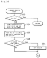
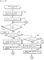
- Figs. 38 and 39 are flowcharts showing the detailed steps of vector detection and the subsequent linkage process.
- the contour extraction unit 10f detects vectors as a function of run-data of two adjacent scanning lines stored in the run-data buffer 3.
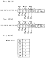
- Figs. 40(a) through 40(c) illustrate the following pointers N1 and N2 and work data Da-Df.
- First address pointer N1 This pointer indicates an address in the first run-data buffer 31, and is initialized to zero at step S0.
- Second address pointer N2 This pointer indicates an address in the second run-data buffer 32, and is initialized to zero at step S0.
- Work data Da through Df Da denotes run-data stored at the address indicated by the first address pointer N1 in the first run-data buffer 31, and Db and Dc denote run-data subsequent to Da.
- Dd denotes run-data stored at the address indicated by the second address pointer N2 in the second run-data buffer 32, and De and Df denote run-data subsequent to Dd.
- the work data Da through Df are stored in the supplementary memory 16.
- step S1 shown in Fig. 38 the values of the address pointers N1 and N2 are respectively increased by two.
- This increment process implies that the addresses of the work data Da and Dd in the run-data buffers 31 and 32 are respectively updated by two as shown by the broken lines in Figs. 40(a) and 40(b).
- the run-data at the address 0 in the run-data buffer 3 indicates the boundary coordinate Xb at which the binary image data changes from zero to one. Since the value of the address pointer N1 is increased by two, the work data Da, Db, and Dc always indicate the positions of the changes of the binary image data from zero to one, one to zero, and zero to one, respectively.
- the work data Dd, De, and Df indicate the same changes as the work data Da, Db, and Dc.
- step S2 the work data Da and Dd are respectively compared with the end data (Nb+1) which indicates the end of each scanning line.
- the program exits from the routine.
- step S3 the program proceeds to step S3 at which the two work data Da and De are compared with each other.
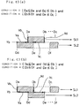
- Fig. 41 illustrates the image fragments when step S4 is to be executed.
- the work data Da, Db, and Dc define an image fragment along a first scanning line SL1, and the work data Dd, De, and Df along a second scanning line SL2.
- the condition that De is less than Da will be hereinafter referred to as 'Condition 1'.
- Yb denotes a boundary coordinate in the secondary scanning direction between the first and the second scanning lines SL1 and SL2.
- the value of the binary image data is always one between the positions indicated by the work data Da and Db, and it is zero between the positions indicated by the work data Db and Dc.
- the value of the binary image data is always one between the positions indicated by the work data Dd and De, and it is zero between the positions indicated by the work data De and Df.
- a vector Va extending from a point (Dd, Yb) to another point (De, Yb) is on the upper boundary of a black image area.
- the contour extraction unit 10f executes the linkage process according to the steps shown in Figs. 36 and 37 to thereby connect the point (Dd, Yb) with the point (De, Yb), and registers specific data concerning the vector Va in the working buffer 5 and the vector data memory 6.
- step S4 After the linkage process is executed at step S4, the program proceeds to step S5 at which the work data Dd, De, and Df are updated and the second address pointer N2 is increased by two, and returns to step S2.
- step S6 When De is not less than Da at step S3, the program goes to step S6 at which the work data Db is compared with the work data Dd. The program proceeds to step S7 when Db is less than Dd, while going to step S9 of Fig. 39 when Db is not less than Dd.
- Fig. 42 illustrates the image fragments under Condition 2 where step S7 is to be executed.
- Condition 2 is expressed as follows: Da ⁇ De and Db ⁇ Dd (Ex3) Under Condition 2, a vector Va extending from a point (Db, Yb) to another point (Da, Yb) is on the lower boundary of a black image area.
- the contour extraction unit 10f executes the linkage process to connect the point (Db, Yb) with the point (Da, Yb), and registers specific data concerning the vector Va in the working buffer 5 and the vector data memory 6.
- the extracting unit 10f also executes the linkage process and registers specific data concerning a vector Vb extending upward from the point (Da, Yb) and another vector Vc extending downward to the point (Db, Yb).
- step S7 After the linkage process is executed at step S7, the program proceeds to step S8 at which the work data Da, Db, and Dc are updated and the first address pointer N1 is increased by two, and returns to step S2.
- Condition 3 is expressed as: Da ⁇ De and Dd ⁇ Db (Ex4)
- the contour extraction unit 10f executes the linkage process to connect one point (Dd, Yb) with another point (Da, Yb) as a vector Va at step S9 of Fig. 39, and registers specific data concerning the vector Va in the working buffer 5 and the vector data memory 6.
- the extracting unit 10f also executes the linkage process and registers specific data concerning a vector Vb extending upward from the point (Da, Yb).
- the work data Df is compared with Db, and the work data De with Dc. Based on the results of the comparison, the above four states are classified into three conditions: that is, Condition 4 corresponding to step S12 and Figs. 43(a) and 43(b); Condition 5 corresponding to step S14 and Fig. 44; and Condition 6 corresponding to step S16 and Fig. 45.
- step S12 is executed when both Condition 3 and Condition 4 are met.
- Condition 4 is expressed as follows: Db ⁇ Df and De ⁇ Dc (Ex5)
- Condition 4 holds in the state shown either in Fig. 43(a) or Fig. 43(b).
- the contour extraction unit 4 executes the linkage process to connect one point (Db, Yb) with another point (De, Yb) as a vector Vc at step S12, and registers specific data concerning the vector Vc in the working buffer 5 and the vector data memory 6.
- the extracting unit 10f also executes the linkage process and registers specific data concerning a vector Vd extending downward to the point (Db, Yb).
- step S14 is executed when both Condition 3 and Condition 5 are met.
- Condition 5 is expressed as: Df ⁇ Db (Ex6)
- the contour extraction unit 10f executes the linkage process to connect one point (Df, Yb) with another point (De, Yb) as a vector Vc at step S14, and registers specific data concerning the vector Vc in the working buffer 5 and the vector data memory 6.
- step S15 the program proceeds to step S15 at which the work data Dd, De, and Df are updated and the second address pointer N2 is increased by two, and returns to step S10.
- step S16 is executed when both Condition 3 and Condition 6 are met.
- Condition 6 is expressed as: Dc ⁇ De (Ex7)
- the contour extraction unit 10f executes the linkage process to connect one point (Db, Yb) with another point (Dc, Yb) as a vector Vc at step S16, and registers specific data concerning the vector Vc in the working buffer 5 and the vector data memory 6.
- the extracting unit 10f also executes the linkage process and registers specific data concerning a vector Vd extending downward to the point (Db, Yb) and another vector Ve extending upward from the point (Dc, Yb).
- Condition 5 the program returns to step S10 and repeats the linkage process and updating of the work data until Condition 4 is met.
- Condition 4 holds at step S10, the program goes to step S12 for executing process under Condition 4, and returns to step S2.
- the contour-extracting apparatus detects contour vectors on the boundary between two adjacent scanning lines as a function of run-data of the two scanning lines stored in the run-data buffer 3.
- Fig. 46 is a flowchart showing the overall processing in the embodiment.
- step T0 it is judged whether the processing is completed for all the scanning lines on an image to be processed at step T0.
- the program proceeds to step T1 at which binary image data of one scanning line is read out from the image data buffer 20.
- step T2 the binary image data is converted to run-data. Since run-data of two scanning lines are stored together in the run-data buffer 3 as explained above, the run-data for the first scanning line is converted at step T2, and then the program skips steps T3, T4, T0, and T1 and returns to step T2 to generate the run-data of the second scanning line.
- run-data of the N-th scanning line is stored in the second run-data buffer 32 while run-data of the (N-1)-th scanning line is stored in the first run-data buffer 31.
- step T3 vectors are detected according to the steps shown in Figs. 38 and 39, and the detected vectors are linked with one another according to the steps shown in Figs. 36 and 37.
- data specifying the closed-loop vector is output at step T3.
- step T4 the set of two adjacent scanning lines to be processed is updated by one scanning line, and repeats steps T0 through T4.
- Figs. 47(a) through 55(d) are explanatory views illustrating an example where contour vectors are detected according to the above method.
- the whole image consists of 8x8 pixels, and includes three image areas R1, R2, and R3 (shaded in the figures) at which the value of the binary image data is one.
- Each set of four figures, such as Figs. 47(a) through 47(d) illustrate the result of the processing executed for one scanning line running through the pixel boundary according to the procedure shown in Fig. 46.
- a scanning line running on the pixel boundary will be herein after referred to as "boundary scanning line”, and a scanning line running on the pixel centers will be referred to as "pixel scanning line”.
- the run-data of a pixel scanning line above the current boundary scanning line is stored in the first run buffer 31 while the run-data of a pixel scanning line below the current boundary scanning line is stored in the second run buffer 32.
- a closed-loop vector CL1 of the area R1 is formed by connecting the coordinate data stored at addresses *1, *2, *7, and *8 in the vector data memory 6 of Fig. 49(d). Data specifying the closed-loop vector CL1 is then output to external devices, and they are eliminated from the working buffer 5 and the vector data memory 6.
- a closed-loop vector CL2 defining the contour of a background area W2 surrounded by the area R2 is formed, and data specifying the closed-loop vector CL2 is output to the external devices.
- the first and the second vector sequences are connected vertically with each other at that boundary coordinate Xb to form a single connected vector sequence.
- each of the registers 5p, 5c, and 5n in the working buffer 5 is only required to store one piece of data corresponding to each boundary coordinate Xb.
- a boundary coordinate Xb of a starting point or a terminal point of a first vector sequence is identical with another boundary coordinate Xb of a starting point or a terminal point of a second vector sequence
- all the three registers 5p, 5c, and 5n is provided with specific data at the identical boundary coordinate Xb.
- This allows to identify the identical boundary coordinate Xb to be of an intermediate point in a single vector sequence, and the first vector sequence is linked with the second vector sequence.
- This processing is the correspondence optimization process described in detail along with Figs. 33(a) through 33(c).
- a significant feature of the contour extracting method is that the working buffer 5 allows to detect a closed-loop of contour vectors while successively updating the boundary scanning line to be processed one by one.
- the run-data along one boundary scanning line, or along two pixel scanning lines is successively processed, and a closed-loop vector sequence defining the contour of image areas is detected without processing all of the run-data for the whole image.
- the contour extracting method allows the downstream apparatus or devices to execute other processing on the image areas defined by the detected closed-loop vectors while the contour extracting apparatus is extracting the closed-loop vectors. The whole image can be therefore efficiently processed in relatively a short time.
Landscapes
- Engineering & Computer Science (AREA)
- Physics & Mathematics (AREA)
- General Physics & Mathematics (AREA)
- Theoretical Computer Science (AREA)
- Multimedia (AREA)
- Signal Processing (AREA)
- Image Processing (AREA)
- Facsimile Image Signal Circuits (AREA)
Applications Claiming Priority (2)
| Application Number | Priority Date | Filing Date | Title |
|---|---|---|---|
| JP69261/93 | 1993-03-03 | ||
| JP5069261A JP2904671B2 (ja) | 1993-03-03 | 1993-03-03 | 多階調画像の修正装置 |
Publications (2)
| Publication Number | Publication Date |
|---|---|
| EP0614154A2 true EP0614154A2 (de) | 1994-09-07 |
| EP0614154A3 EP0614154A3 (de) | 1994-10-26 |
Family
ID=13397594
Family Applications (1)
| Application Number | Title | Priority Date | Filing Date |
|---|---|---|---|
| EP19940103065 Withdrawn EP0614154A3 (de) | 1993-03-03 | 1994-03-01 | Verfahren und Vorrichtung zur Verbesserung von Mehrtonbildern. |
Country Status (3)
| Country | Link |
|---|---|
| US (1) | US5724454A (de) |
| EP (1) | EP0614154A3 (de) |
| JP (1) | JP2904671B2 (de) |
Cited By (1)
| Publication number | Priority date | Publication date | Assignee | Title |
|---|---|---|---|---|
| EP0752683A3 (de) * | 1995-07-07 | 1997-09-17 | Dainippon Screen Mfg | Verfahren zur Veränderung eines Mehrtonbildes |
Families Citing this family (10)
| Publication number | Priority date | Publication date | Assignee | Title |
|---|---|---|---|---|
| US6289136B1 (en) | 1995-03-22 | 2001-09-11 | Canon Kabushiki Kaisha | Image processing method and apparatus |
| US5923775A (en) * | 1996-04-04 | 1999-07-13 | Eastman Kodak Company | Apparatus and method for signal dependent noise estimation and reduction in digital images |
| JP2001188910A (ja) * | 1999-10-22 | 2001-07-10 | Toshiba Corp | 画像の輪郭抽出方法、画像からの物体抽出方法およびこの物体抽出方法を用いた画像伝送システム |
| JP3516937B2 (ja) * | 2001-09-19 | 2004-04-05 | 株式会社Pfu | 画像読み取りシステムの制御方法およびその制御プログラム |
| US6990255B2 (en) * | 2001-09-19 | 2006-01-24 | Romanik Philip B | Image defect display system |
| US7031549B2 (en) * | 2002-02-22 | 2006-04-18 | Hewlett-Packard Development Company, L.P. | Systems and methods for enhancing tone reproduction |
| US7356193B2 (en) * | 2004-04-01 | 2008-04-08 | Eastman Kodak Company | Detection of hanging wires in digital color images |
| JP4652717B2 (ja) | 2004-04-26 | 2011-03-16 | 株式会社ミツトヨ | 画像処理装置及び方法並びにプログラム |
| JP4968192B2 (ja) * | 2008-06-18 | 2012-07-04 | コニカミノルタビジネステクノロジーズ株式会社 | 画像処理装置、画像処理プログラム、および画像処理方法 |
| US8189943B2 (en) * | 2009-03-17 | 2012-05-29 | Mitsubishi Electric Research Laboratories, Inc. | Method for up-sampling depth images |
Family Cites Families (12)
| Publication number | Priority date | Publication date | Assignee | Title |
|---|---|---|---|---|
| US4520505A (en) * | 1981-12-23 | 1985-05-28 | Mitsubishi Denki Kabushiki Kaisha | Character reading device |
| US4698843A (en) * | 1985-08-19 | 1987-10-06 | Rca Corporation | Method for compensating for void-defects in images |
| JPS63265371A (ja) * | 1986-12-15 | 1988-11-01 | Toshiba Corp | 線図形つなぎ装置 |
| GB2199803B (en) * | 1987-01-20 | 1991-05-29 | Sanwa Shutter Corp | Elevation bed |
| JP3014097B2 (ja) * | 1987-02-20 | 2000-02-28 | 株式会社日立製作所 | 輪郭追跡方法及びシステム |
| US5181255A (en) * | 1990-12-13 | 1993-01-19 | Xerox Corporation | Segmentation of handwriting and machine printed text |
| JPH0425980A (ja) * | 1990-05-22 | 1992-01-29 | Fuji Photo Film Co Ltd | ノイズ除去方法 |
| US5131058A (en) * | 1990-08-24 | 1992-07-14 | Eastman Kodak Company | Method for obtaining output-adjusted color separations |
| JPH04107069A (ja) * | 1990-08-28 | 1992-04-08 | Toshiba Corp | 二値画像から多階調画像への変換装置 |
| JP2958584B2 (ja) * | 1991-09-19 | 1999-10-06 | 富士写真フイルム株式会社 | ノイズ除去方法 |
| JP2845384B2 (ja) * | 1991-11-14 | 1999-01-13 | キヤノン株式会社 | 画像処理装置 |
| US5341224A (en) * | 1992-04-17 | 1994-08-23 | Xerox Corporation | Image processing system and method for employing adaptive scanning of halftones to provide better printable images |
-
1993
- 1993-03-03 JP JP5069261A patent/JP2904671B2/ja not_active Expired - Fee Related
-
1994
- 1994-03-01 EP EP19940103065 patent/EP0614154A3/de not_active Withdrawn
-
1995
- 1995-12-07 US US08/573,599 patent/US5724454A/en not_active Expired - Fee Related
Cited By (2)
| Publication number | Priority date | Publication date | Assignee | Title |
|---|---|---|---|---|
| EP0752683A3 (de) * | 1995-07-07 | 1997-09-17 | Dainippon Screen Mfg | Verfahren zur Veränderung eines Mehrtonbildes |
| US5949913A (en) * | 1995-07-07 | 1999-09-07 | Dainippon Screen Mfg. Co., Ltd. | Method and apparatus for modifying multi-tone image |
Also Published As
| Publication number | Publication date |
|---|---|
| JP2904671B2 (ja) | 1999-06-14 |
| US5724454A (en) | 1998-03-03 |
| JPH06261209A (ja) | 1994-09-16 |
| EP0614154A3 (de) | 1994-10-26 |
Similar Documents
| Publication | Publication Date | Title |
|---|---|---|
| US5379350A (en) | Method and apparatus for extracting a contour of an image | |
| US6226400B1 (en) | Defining color borders in a raster image by identifying and breaking contrast ties | |
| US5724454A (en) | Method and apparatus for correcting a multi-tone image | |
| US6844942B2 (en) | Method for trapping raster data in a run-length encoded form | |
| JPH04218095A (ja) | 画像処理装置およびデータ処理システム | |
| EP0228553A2 (de) | Gerät und Verfahren zur Verarbeitung von Bildern mit verschiedenen Bildpunktwerten | |
| US5054091A (en) | Method for determining coordinates of circumscribed rectangular frame of each character for use in optical character reader | |
| US6728399B1 (en) | Method and apparatus for defining color borders in a raster image by identifying and breaking contrast ties | |
| EP0642256A2 (de) | Ein Detektionssystem in einem Durchlauf für Bildbereiche, die von einer Markierung umschlossen sind und Verfahren für einen Photokopierer | |
| JP2002368988A (ja) | ピクセル内でラスタ化された、リデジタル化2値画像データのレタッチ方法 | |
| JPH06203153A (ja) | 画像処理方法及び装置 | |
| EP0477904B1 (de) | Verfahren und Gerät zur Erzeugung verkleinerter Bilder | |
| CN109671081B (zh) | 一种基于fpga查找表的坏簇统计方法及装置 | |
| US5920648A (en) | Image processing method and apparatus which replace horizontal and vertical vectors with an inclined vector | |
| US6324300B1 (en) | Defining color borders in a raster image | |
| EP0282972B1 (de) | Gerät zur Bildkonturentdeckung | |
| US5949913A (en) | Method and apparatus for modifying multi-tone image | |
| EP0477956A2 (de) | Verfahren und Vorrichtung zur Bildverarbeitung von Linienumrandungen | |
| US5454070A (en) | Pixel to spline based region conversion method | |
| US5323250A (en) | Pixel-skipping apparatus in an image processor | |
| JPH05342340A (ja) | 画像処理方法及びその装置 | |
| JPH09281939A (ja) | 表示装置 | |
| JPH07182503A (ja) | 画像処理方法及び装置 | |
| JP3564216B2 (ja) | 画像処理装置 | |
| JP2005142951A (ja) | 画像読取装置、および画像評価プログラム |
Legal Events
| Date | Code | Title | Description |
|---|---|---|---|
| PUAI | Public reference made under article 153(3) epc to a published international application that has entered the european phase |
Free format text: ORIGINAL CODE: 0009012 |
|
| AK | Designated contracting states |
Kind code of ref document: A2 Designated state(s): DE FR GB |
|
| PUAL | Search report despatched |
Free format text: ORIGINAL CODE: 0009013 |
|
| AK | Designated contracting states |
Kind code of ref document: A3 Designated state(s): DE FR GB |
|
| 17P | Request for examination filed |
Effective date: 19950127 |
|
| 17Q | First examination report despatched |
Effective date: 19990112 |
|
| STAA | Information on the status of an ep patent application or granted ep patent |
Free format text: STATUS: THE APPLICATION IS DEEMED TO BE WITHDRAWN |
|
| 18D | Application deemed to be withdrawn |
Effective date: 19990526 |