EP0614405B2 - Verfahren zur verbindung von platten - Google Patents
Verfahren zur verbindung von platten Download PDFInfo
- Publication number
- EP0614405B2 EP0614405B2 EP92923611A EP92923611A EP0614405B2 EP 0614405 B2 EP0614405 B2 EP 0614405B2 EP 92923611 A EP92923611 A EP 92923611A EP 92923611 A EP92923611 A EP 92923611A EP 0614405 B2 EP0614405 B2 EP 0614405B2
- Authority
- EP
- European Patent Office
- Prior art keywords
- rivet
- panels
- slug
- punch
- panel
- Prior art date
- Legal status (The legal status is an assumption and is not a legal conclusion. Google has not performed a legal analysis and makes no representation as to the accuracy of the status listed.)
- Expired - Lifetime
Links
Images


Classifications
-
- B—PERFORMING OPERATIONS; TRANSPORTING
- B21—MECHANICAL METAL-WORKING WITHOUT ESSENTIALLY REMOVING MATERIAL; PUNCHING METAL
- B21J—FORGING; HAMMERING; PRESSING METAL; RIVETING; FORGE FURNACES
- B21J15/00—Riveting
- B21J15/02—Riveting procedures
- B21J15/025—Setting self-piercing rivets
-
- B—PERFORMING OPERATIONS; TRANSPORTING
- B21—MECHANICAL METAL-WORKING WITHOUT ESSENTIALLY REMOVING MATERIAL; PUNCHING METAL
- B21D—WORKING OR PROCESSING OF SHEET METAL OR METAL TUBES, RODS OR PROFILES WITHOUT ESSENTIALLY REMOVING MATERIAL; PUNCHING METAL
- B21D39/00—Application of procedures in order to connect objects or parts, e.g. coating with sheet metal otherwise than by plating; Tube expanders
- B21D39/03—Application of procedures in order to connect objects or parts, e.g. coating with sheet metal otherwise than by plating; Tube expanders of sheet metal otherwise than by folding
- B21D39/031—Joining superposed plates by locally deforming without slitting or piercing
-
- B—PERFORMING OPERATIONS; TRANSPORTING
- B21—MECHANICAL METAL-WORKING WITHOUT ESSENTIALLY REMOVING MATERIAL; PUNCHING METAL
- B21J—FORGING; HAMMERING; PRESSING METAL; RIVETING; FORGE FURNACES
- B21J15/00—Riveting
- B21J15/10—Riveting machines
- B21J15/36—Rivet sets, i.e. tools for forming heads; Mandrels for expanding parts of hollow rivets
Definitions
- This invention relates to improved panel clinching methods.
- the term “clinching” is also known as “press joining” or “integral fastening”.
- Spot welding is the most commonly used technique for joining vehicle body components in the automotive industries. As the strength of each spot weld cannot be guaranteed, eg. due to the inclusion of rubbish between the components, or poor weld penetration, designers must increase the number of welds to ensure adequate joint strength.
- Aluminium has great potential in the automobile field due to its light weight, but the lack of a suitable spot welding method is one reason which has minimised its application.
- a further alternative method is metal clinching, where two sheets of metal are deformed into a locking engagement using a punch-and-die combination. Examples of metal clinching methods are disclosed in:
- a panel clinching method according to claim 1.
- the rivet or slug may be inserted into the joint as the joint is formed, the rivet or slug co-operating with the punch to deform the panels into the supporting die.
- the rivet or slug co-operates with the metal panels into the die, and a sleeve external to the punch then deforms the rivet or slug within the joint.
- the bore of the rivet or slug may be threaded, serrated or otherwise profiled to engage and support an anchor for, eg. a wiring loom support, a trim cover panel fastener or the like.
- a plastic insert may be fitted to the rivet or slug to provide a flush outer face.
- the panels are pre-clamped to the die before the punch drives the rivet or slug into the panels to form the clinched joint; or before the clinched joint is formed and the rivet or slug is then inserted into the joint.
- the invention is particularly suitable for joining sheet metal panels, it is also suitable for polymeric materials (eg. Polyethylene, polyurethane, polypropylene, nylon) where one or more metal panels are substituted by panels of polymeric material.
- polymeric materials eg. Polyethylene, polyurethane, polypropylene, nylon
- the methods are suitable for joining, eg. An aluminium sheet to a polypropylene sheet, where the polymeric sheet may be locally preheated (eg. By the supporting die) to assist in the "flow" of the polymeric material as the joint is formed.
- the rings or components may also be formed of polymeric material and be clinched to metal and/or polymeric material sheets.
- the shanks of the rivets or slugs may be provided with external splines, grooves, teeth or other protrusions or recesses to provide additional grip between the rivets or slugs and the panels in the clinched joint.
- Adhesives can be applied, eg. to the shanks of the rivets or slugs to assist bonding of the rivets or slugs to the panels. Adhesives may also be provided within the bore of the tubular or semi-tubular rivets or slugs to be extruded into the clinched joint, as the rivets or slugs are deformed, to assist the bonding of the rivets or slugs to the panels.
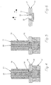
- the metal panels 12, 13 to be joined together are supported on the die assembly 14 of a clinching tool(s), the die assembly having expandable and contractable collets 16 associated with a collet holder 17 and anvil 18 arranged to allow the joint 11 to be released when formed.
- the clinching tool 15 has a pre-clamping head 19 which clamps the metal panels 12, 13 to the die assembly and has internal (spring-loaded) balls 19A to locate and centralise the rivet 10.
- a punch 20 is slidably journalled in a sleeve 21, slidably journalled in the pre-clamping head 19, and the punch 20 and sleeve 21 are connected to respective hydraulic rams (not shown).
- the punch 20 is driven through the rivet 10 into engagement with the upper panel 12; the sleeve 21 engaging the rivet 10.
- the punch 20 and rivet 10 are advanced to deform the metal panels 12,13 into the die assembly 14 (see FIG 4).
- the sleeve 21 is then advanced to cause the inner end of the rivet 10 to be outwardly-deformed (see FIGS 5 and 6).
- the anvil 18 can be spring-loaded or forcibly raised as a post-forming operation against the punch 20 to assist in deforming the rivet or slug.
- the insertion and deformation of the rivet assists in locking the metal panels 12, 13 together, with increase in the shear and axial separation strength(s) (ie. in the direction of arrows A and B, respectively).
- the bore 22 of the rivet 10 may be threaded to receive a fastener or plug to support, eg. an electrical wiring loom or a plastic insert to form a flush cover for the clinched joint 11.
- a modified tubular rivet 110 has a tapered end 123 to its inner bore 122.
- the sleeve 21 is eliminated and the punch 120 is slidably journalled in the pre-clamping head 119.
- the metal sheets 112, 113 are supported by the die assembly 114 and clamped thereto by the clamping head 119.
- the punch 120 engages the rivet 110 (see FIG 9) and drives the rivet 110 into the metal panels 112, 113 which are deformed into the die assembly 114 (see FIG 10).
- the punch 120 is further advanced (see FIG 11) to deform the inner end of the rivet 110 to form the clinched joint 111 (see FIG 12).
- a solid or semi-tubular rivet or slug may be used.
- a solid slug 210 (FIG 13) has a concave recess 222 at its lower end and is used to form the clinched joint 211 of FIG 16.
- the metal sheets 212, 213 are clamped to the die assembly 214 by the clamping head 219 (see FIG 14).
- the punch 220 is advanced to drive the slug 210 (as an extension of the punch 220) into the metal panels 212, 213 to deform the panels into the die assembly 214 to form the clinched joint 211.
- the head of the slug 210 is flush with the outer face of panel 212 and such a joint is suitable where aesthetic appeal is required, eg. on a visible surface of a vehicle body.
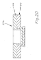
- the semi-tubular slug 310 (see FIG 17) has a tapered end 323 to its bore 322.
- the metal panels 312, 313 are pre-clamped to the die assembly 314 by the clamping head 319 and the punch 320 is advanced (see FIG 19) to form a conventional button-type clinched joint 311A (see FIG 20).
- the punch 320 is retracted and a semi-tubular slug 310 is placed in the clinching tool.
- the pre-clamping head 319 clamps the panels (see FIG 21) and the punch 320 is advanced to drive the slug 310 into the clinched joint 311A to deform the slug 310 to form the clinched joint 311 (see FIG 23).
- a component 510 (see FIGS 24 to 26), with a tapered recess or bore 522, and a screw-threaded hole 525 (as part of a sub-assembly - not shown) can also be employed as the die for the clinched joint 511 and provide a mount for the sub-assembly secured to the panels 512, 513.
- a solid slug 210 can be pressed into the clinched joint 511.
- the slug 210 may be screw-threaded and have a slot, Philips-head slot or an Allen-head recess to enable the slug 210 to be removed later if required for dis-assembly of the joint 511).
- FIGS 27 to 29 show the attachment of a second component 610, with a bore 622 and a plain spigot (FIG 27) or screw-threaded end spigot 626 (FIG 28), secured to the clinch-joint 611.
- the spigot may also be profiled, e.g. engageable in a catch or lock means).
- FIG 29 shows the component 610 supported by a die assembly 614 during the clinching step.
- one or both panels may be a polymeric sheet (e.g. polypropylene), it being preferred that the inner sheet, (e.g. 13, 113) being the polymeric sheet and the die assembly may be heated at the location of the clinched joint to assist "flow" of the polymeric material.
- a polymeric sheet e.g. polypropylene
- the inner sheet e.g. 13, 113
- the die assembly may be heated at the location of the clinched joint to assist "flow" of the polymeric material.
- the rivets 10, 110; slugs 210, 310; or components 510, 610 be of the same type of material as the panels as this will obviate the need for disassembly of the joints.
- the use of an 8mm solid rivet or slug in conjunction with a clinched joint increase the shear strength of a sheet metal joint by 50% and the strength to both the shear and axial separation directions can be maintained within controlled limits, unlike spot welds.
- This means the number of clinched joints can be much less than the number of spot welds, and joints can also support sub-assemblies.
Landscapes
- Engineering & Computer Science (AREA)
- Mechanical Engineering (AREA)
- Insertion Pins And Rivets (AREA)
- Connection Of Plates (AREA)
- Joining Of Building Structures In Genera (AREA)
- Dry Formation Of Fiberboard And The Like (AREA)
- Chemical And Physical Treatments For Wood And The Like (AREA)
- Finishing Walls (AREA)
Claims (11)
- Platten-Vernietungsmethode für das Vernieten von mindestens zwei Platten (12, 13) miteinander, bei der ein röhrenförmiger Niet oder Rohling durch eine Obergesenkeinheit (20, 21) in eine Vernietungsstelle (11) zwischen den Platten (12, 13) getrieben oder eingeführt wird, um die zu verbindenden Platten (12, 13) in einem stützenden Untergesenk (14) zu verformen, wobei der Niet oder Rohling mit der Obergesenkeinheit zusammenwirkt, um die Platten (12, 13) zu verformen, dadurch gekennzeichnet, daß die Obergesenkeinheit ein Obergesenk (20) und eine Hülse (21) äußerlich zum Obergesenk (20) aufweist, wobei das Obergesenk (20) durch den Niet oder Rohling (10) in Eingriff mit der oberen Platte (12) getrieben wird, wobei das Obergesenk und der Niet vorwärtsbewegt werden, um die Platten (12, 13) zu verformen, und wobei die Hülse relativ zum Obergesenk (20) vorwärtsbewegt wird, um mindestens ein inneres Ende eines Schaftes des Niets oder Rohlings (10) innerhalb der Vernietungsstelle (11) nach außen zu verformen; und daß der Niet oder Rohling (10) die Platten (12, 13) nicht durchdringt.
- Platten-Vernietungsmethode nach Anspruch 1, bei der die zu verbindenden Platten im voraus an das Untergesenk (14) gespannt werden, bevor die Obergesenkeinheit (20, 21) den Niet oder Rohling (10) in die Platten (12, 13) treibt, um die Vernietungsstelle (11) zu bilden.
- Platten-Vernietungsmethode nach einem der vorhergehenden Ansprüche, bei der mindestens eine Platte ein Blech ist und mindestens eine Platte eine polymere Tafel ist, wobei die polymere Tafel im Bereich der Vernietungsstelle im voraus erwärmt wird, um den Fluß des polymeren Materials beim Verformen der Platten zu fördern.
- Platten-Vernietungsmethode nach einem der vorhergehenden Ansprüche, bei der ein Kleber auf den Niet oder Rohling (10) aufgetragen wird, um die Verbindung zwischen den Platten (12, 13) und dem Niet oder Rohling (10) zu unterstützen.
- Platten-Vernietungsmethode nach Anspruch 1, bei der ein Kleber in eine Bohrung des röhrenförmigen Niets oder Rohlings (10) gegeben wird, wobei der Kleber beim Verformen des röhrenförmigen Niets oder Rohlings (10) in die Vernietungsstelle (11) extrudiert wird, um die Verbindung zwischen den Platten (12, 13) und dem Niet oder Rohling (10) zu unterstützen.
- Platten-Vernietungsmethode nach einem der vorhergehenden Ansprüche, bei der der Niet oder Rohling (10) einen Schaft mit externen Streifen, Rillen, Zähnen oder anderen Vorsprüngen oder Vertiefungen aufweist, um einen zusätzlichen Halt zwischen dem Niet oder Rohling (10) und den Platten in der Vernietungsstelle (11) zu bewirken.
- Platten-Vernietungsmethode für das Vernieten von mindestens zwei Platten (312, 313) miteinander, wobei ein massiver oder halbröhrenförmiger Niet oder Rohling (310) verwendet wird, bei der ein Obergesenk eine übliche knopfartige Vernietungsstelle (311) in den zu verbindenden Platten (312, 313) bildet, wobei die Platten von einem Untergesenk (314) gestützt werden und das Obergesenk (320) danach zurückgezogen wird, dadurch gekennzeichnet, daß der Niet oder Rohling (310) zwischen dem Obergesenk (320) und der Vernietungsstelle (311) angeordnet wird; und daß das Obergesenk (320) vorwärtsbewegt wird, um den Niet oder Rohling (310) in die Vernietungsstelle (311) zu treiben, um die zu verbindenden Platten (312, 313) im stützenden Untergesenk zu verformen, und um mindestens das innere Ende des Schaftes des Niets oder Rohlings in der Vernietungsstelle (311) nach außen zu verformen; und daß der Niet oder Rohling (310) die Platten (312, 313) nicht durchdringt.
- Platten-Vernietungsmethode nach Anspruch 7, bei der mindestens eine Platte (312, 313) ein Blech ist und mindestens eine Platte eine polymere Tafel ist, wobei die polymere Tafel im Bereich der Vernietungsstelle im voraus erwärmt wird, um den Fluß des polymeren Materials beim Verformen der Platten zu fördern.
- Platten-Vernietungsmethode nach Anspruch 7 oder 8, bei der ein Kleber auf den Niet oder Rohling (310) aufgetragen wird, um die Verbindung zwischen den Platten (312, 313) und dem Niet oder Rohling (310) zu unterstützen.
- Platten-Vernietungsmethode für das Vernieten von mindestens zwei Platten (112, 113) miteinander, wobei ein Niet (110) mit einer Bohrung (122) mit einem konischen Ende (123) und einen Schaft mit einem inneren Ende einschließend verwendet wird, wobei die Methode die folgenden Schritte aufweist:Bereitstellen eines Obergesenks (120) mit einem Hauptkörper mit einem Eingriffsvorsprung und einem unteren Ende mit verringertem Durchmesser, um in die Bohrung (122) des Niets (110) zu passen;Stützen der Platten (112, 113) auf einem stützenden Untergesenk und Spannen der Platten mit einem Vorspannkopf (119);Anordnen des Niets (110) zwischen den Platten (112, 113) und dem Obergesenk (120); gekennzeichnet durch:Vorwärtsbewegen des Obergesenks (120), bis der Vorsprung des Hauptkörpers mit dem Oberteil des Niets (110) in Eingriff kommt;weiteres Vorwärtsbewegen des Obergesenks (120) nach unten, um die Platten (112, 113) im Untergesenk (114) zu verformen, und um die Vernietungsstelle (111) zu bilden; unddanach wiederum Vorwärtsbewegen des Obergesenks (120) nach unten, um zu bewirken, daß mindestens das innere Ende des Schaftes des Niets (110) nach außen verformt wird, wodurch folglich die Platten (112, 113) verformt werden, um die Vernietungsstelle ohne Durchdringen der Platten durch den Niet (110) zu sichern.
- Platten-Vernietungsmethode nach Anspruch 10, bei der das untere Ende des Obergesenks eine Höhe aufweist, die geringer ist als die Höhe des Niets (110), und bei der, wenn der Vorsprung mit dem Niet (110) in Eingriff ist, das untere Ende des Obergesenks (120) etwas über den Platten (112, 113) beabstandet ist.
Applications Claiming Priority (4)
| Application Number | Priority Date | Filing Date | Title |
|---|---|---|---|
| AU9742/91 | 1991-11-27 | ||
| AU974291 | 1991-11-27 | ||
| AUPK974291 | 1991-11-27 | ||
| PCT/AU1992/000631 WO1993010925A1 (en) | 1991-11-27 | 1992-11-25 | Improved panel clinching methods |
Publications (4)
| Publication Number | Publication Date |
|---|---|
| EP0614405A1 EP0614405A1 (de) | 1994-09-14 |
| EP0614405A4 EP0614405A4 (en) | 1997-02-05 |
| EP0614405B1 EP0614405B1 (de) | 1999-11-10 |
| EP0614405B2 true EP0614405B2 (de) | 2004-12-29 |
Family
ID=3775852
Family Applications (1)
| Application Number | Title | Priority Date | Filing Date |
|---|---|---|---|
| EP92923611A Expired - Lifetime EP0614405B2 (de) | 1991-11-27 | 1992-11-25 | Verfahren zur verbindung von platten |
Country Status (12)
| Country | Link |
|---|---|
| EP (1) | EP0614405B2 (de) |
| JP (1) | JP3346566B2 (de) |
| KR (1) | KR100270634B1 (de) |
| CN (1) | CN1041287C (de) |
| AT (1) | ATE186484T1 (de) |
| BR (1) | BR9206821A (de) |
| CA (1) | CA2123886A1 (de) |
| DE (1) | DE69230291T3 (de) |
| ES (1) | ES2141115T3 (de) |
| IN (1) | IN178893B (de) |
| MX (1) | MX9206870A (de) |
| WO (1) | WO1993010925A1 (de) |
Families Citing this family (49)
| Publication number | Priority date | Publication date | Assignee | Title |
|---|---|---|---|---|
| GB9226517D0 (en) * | 1992-12-19 | 1993-02-10 | Henrob Ltd | Improvements in or relating to sefl-piercing riveting |
| GB9601181D0 (en) * | 1996-01-20 | 1996-03-20 | Trico Ltd | Improvements relating to wiper arm assemblies |
| GB2314794B (en) * | 1996-07-04 | 1999-01-06 | Avdel Textron Ltd | Self piercing riveting |
| DE19701780A1 (de) | 1997-01-20 | 1998-07-23 | Emhart Inc | Stanzniet und mit ihm erstellte Nietverbindungen sowie Nietwerkzeug und Verfahrensherstellung einer Nietverbindung |
| DE19714129A1 (de) * | 1997-04-05 | 1998-10-15 | Eckold Vorrichtung | Fügeverfahren und -vorrichtung |
| WO1999001241A1 (en) * | 1997-07-02 | 1999-01-14 | Sanyo Machine Works, Ltd. | Method of joining metallic sheets |
| US6276050B1 (en) | 1998-07-20 | 2001-08-21 | Emhart Inc. | Riveting system and process for forming a riveted joint |
| US9015920B2 (en) | 1997-07-21 | 2015-04-28 | Newfrey Llc | Riveting system and process for forming a riveted joint |
| CN1096319C (zh) * | 1997-11-17 | 2002-12-18 | 德累斯顿工业技术大学 | 热辅机械连接的方法和装置 |
| US6722013B1 (en) | 1998-03-25 | 2004-04-20 | Tox Pressotechnik Gmbh | Method, tool and punch for joining components to a plate |
| CA2378817A1 (en) * | 1999-07-09 | 2001-01-18 | Profil Verbindungstechnik Gmbh & Co. Kg | Method for placing a functional element; die, functional element; assembly element and die arrangement |
| WO2001030516A1 (en) | 1999-10-26 | 2001-05-03 | Toyota Jidosha Kabushiki Kaisha | Rivet, riveted joint structure, riveting apparatus, and riveting method |
| GB0111265D0 (en) * | 2001-05-05 | 2001-06-27 | Henrob Ltd | Fastener insertion apparatus and method |
| JP2004520941A (ja) * | 2001-05-11 | 2004-07-15 | トックス・プレッソテヒニック・ゲゼルシャフト・ミト・ベシュレンクテル・ハフツング・ウント・コンパニー・コマンディトゲゼルシャフト | 板を機械的に結合するための工具 |
| DE10238020A1 (de) | 2001-08-23 | 2004-03-04 | Brose Fahrzeugteile Gmbh & Co. Kommanditgesellschaft, Coburg | Kraftfahrzeug-Baugruppe |
| DE10213793A1 (de) * | 2002-03-27 | 2003-10-09 | Fraunhofer Ges Forschung | Verfahren, Vorrichtung und Hilfsfügeteil zum Fügen von mindestens zwei Bauteilen |
| DE10250342A1 (de) * | 2002-10-29 | 2004-05-19 | Daimlerchrysler Ag | Fügeverfahren und Fügevorrichtung zum Verbinden von überlappend angeordneten Fügeteilen |
| JP4306507B2 (ja) * | 2004-03-26 | 2009-08-05 | 日産自動車株式会社 | 板材のかしめ接合方法、および板材のかしめ接合装置 |
| DE102004029230A1 (de) * | 2004-06-17 | 2006-01-12 | Thyssenkrupp Stahl Ag | Verfahren zum Verbinden von zwei insbesondere aus Metall bestehenden Fügepartnern mittels Überlappstoß und durch Fügen hergestelltes Bauteil |
| CN100383409C (zh) * | 2004-06-25 | 2008-04-23 | 达方电子股份有限公司 | 金属板铆接方法和铆接装置 |
| DE102005031917A1 (de) † | 2004-09-24 | 2006-04-13 | Böllhoff Verbindungstechnik GmbH | Verfahren zum Fügen und Vorrichtung zum Betätigen eines Fügewerkzeuges |
| CN100513005C (zh) * | 2005-11-16 | 2009-07-15 | 深圳市比克电池有限公司 | 板件铆接装置及采用该装置进行板件铆接的方法 |
| GB0813883D0 (en) | 2008-07-30 | 2008-09-03 | Henrob Ltd | Joining apparatus and method |
| GB201017004D0 (en) | 2010-10-08 | 2010-11-24 | Henrob Ltd | Fastener delivery apparatus |
| ES2663305T3 (es) | 2010-11-10 | 2018-04-11 | Henrob Limited | Método de remachado |
| WO2012165151A1 (ja) | 2011-06-02 | 2012-12-06 | 株式会社青山製作所 | 嵌め部材の嵌め方法及び装置 |
| JP2013059770A (ja) * | 2011-09-12 | 2013-04-04 | Toyota Motor Corp | 部材の接続方法 |
| DE102012001088A1 (de) | 2012-01-20 | 2013-07-25 | Profil Verbindungstechnik Gmbh & Co. Kg | Zweiteiliges Mutterelement für Kunststoffbauteile |
| DE102012001086A1 (de) * | 2012-01-20 | 2013-07-25 | Profil Verbindungstechnik Gmbh & Co. Kg | Bolzenelement und Verfahren zur Anbringung eines Bolzenelements an einem Bauteil aus einem Verbundwerkstoff |
| DE102012001068A1 (de) | 2012-01-20 | 2013-07-25 | Profil Verbindungstechnik Gmbh & Co. Kg | Verfahren zur Anbringung eines hohlen Elements wie ein Hohlniet oder ein Mutterelement an einem aus einem Verbundwerkstoff bestehenden Bauteil |
| DE102012003819A1 (de) | 2012-02-27 | 2013-08-29 | Profil Verbindungstechnik Gmbh & Co. Kg | Funktionselement zur fluiddichten Anbringung an ein Blechteil, Zusammenbauteil und Verfahren |
| DE102012008798B4 (de) * | 2012-03-31 | 2016-01-14 | Johnson Controls Gmbh | Verfahren zum Fügen sowie Verbindungselement |
| US9027220B2 (en) | 2012-08-07 | 2015-05-12 | Newfrey Llc | Rivet setting machine |
| CN103410261B (zh) * | 2013-08-01 | 2016-02-03 | 斯泰科技(杭州)有限公司 | 一种高安全切底铆栓及建筑附属物的连接结构 |
| CN105916612B (zh) | 2014-01-16 | 2019-03-08 | 亨罗布有限公司 | 线性致动器组件 |
| DE102014000624B4 (de) * | 2014-01-18 | 2016-07-28 | Audi Ag | Verfahren zum Fügen von zumindest zwei zumindest in einer Fügezone überlappend angeordneten Fügeteilen unter Verwendung eines Fügelements |
| DE102014007330A1 (de) * | 2014-05-15 | 2015-11-19 | Fraunhofer-Gesellschaft zur Förderung der angewandten Forschung e.V. | Halbhohlstanzniet und Verfahren zum Herstellen einer Fügeverbindung |
| EP3012470B1 (de) * | 2014-10-24 | 2018-02-21 | NEDSCHROEF PLETTENBERG GmbH | Mutter zur Befestigung an einem Blech |
| CN105414437B (zh) * | 2015-11-20 | 2018-01-16 | 西安交通大学 | 一种使用软质铆柱的预压孔与铆压复合的板材连接方法 |
| CN105478646B (zh) * | 2015-11-20 | 2017-11-03 | 西安交通大学 | 一种使用硬质铆柱一步法铆压的板材连接方法 |
| KR101811416B1 (ko) * | 2016-08-29 | 2017-12-21 | (주)호원 | 이종소재용 결합장치 |
| CN107626875B (zh) * | 2017-09-30 | 2019-07-16 | 昆明理工大学 | 一种实心钉杆辅助的半空心自冲铆铆钉装置及铆接方法 |
| JP7035695B2 (ja) * | 2018-03-26 | 2022-03-15 | トヨタ自動車株式会社 | 接合装置および接合体の製造方法 |
| KR102081744B1 (ko) * | 2018-10-02 | 2020-02-26 | 주식회사 성우하이텍 | 하이브리드 접합장치 및 그를 이용한 접합구조체의 제조방법 |
| KR102081742B1 (ko) * | 2018-10-02 | 2020-02-26 | 주식회사 성우하이텍 | 하이브리드 접합장치 및 그를 이용한 접합구조체의 제조방법 |
| KR102081737B1 (ko) * | 2018-10-02 | 2020-02-26 | 주식회사 성우하이텍 | 하이브리드 접합장치 및 그를 이용한 접합구조체의 제조방법 |
| SG11202104938YA (en) * | 2018-11-15 | 2021-06-29 | Penn Eng & Mfg Corp | Machine tooling with rotary punch |
| US11185912B2 (en) * | 2019-10-29 | 2021-11-30 | The Boeing Company | Automated rivet apparatus for automated installation of semi-tubular fastener rivets |
| CN116274831B (zh) * | 2023-02-07 | 2025-07-01 | 上海交通大学 | 基于铆钉调控的平模回填铆接方法 |
Citations (2)
| Publication number | Priority date | Publication date | Assignee | Title |
|---|---|---|---|---|
| DE2140936B2 (de) † | 1971-08-16 | 1973-08-09 | Siebau Siegener Stahlbauten Gmbh, 5910 Kreuztal | Verfahren zum verbinden von blechen |
| EP0077932B1 (de) † | 1981-10-28 | 1984-12-27 | WALTER ECKOLD GmbH & Co. KG Vorrichtungs- und Gerätebau | Vorrichtung zum nietartigen Verbinden von Blechen |
Family Cites Families (13)
| Publication number | Priority date | Publication date | Assignee | Title |
|---|---|---|---|---|
| US2465534A (en) * | 1944-09-18 | 1949-03-29 | Judson L Thomson Mfg Company | Rivet and method of making joints therewith |
| US3022687A (en) * | 1953-11-20 | 1962-02-27 | Arthur J Richards | Method of riveting |
| GB912516A (en) * | 1960-10-21 | 1962-12-12 | Belling & Lee Ltd | Improvements in or relating to a method of securing an insert in sheet material |
| US3198155A (en) * | 1964-03-02 | 1965-08-03 | Ermal C Fraze | Method of interconnecting two sheets of deformable material |
| GB2141369B (en) * | 1983-06-15 | 1986-11-19 | Bl Tech Ltd | Rivetting |
| US4859289A (en) * | 1986-05-26 | 1989-08-22 | Sumitomo Electric Industries, Ltd. | Process for producing a metal wire useful as rubber product reinforcement |
| DE3726392A1 (de) * | 1987-08-07 | 1989-02-16 | Kuka Schweissanlagen & Roboter | Verfahren zum verbinden aufeinanderliegender duenner platten oder plattenabschnitte |
| DE3824817A1 (de) * | 1988-07-21 | 1990-01-25 | Hilti Ag | Verfahren zum verbinden duenner bauteile und befestigungselementen hierzu |
| DE3923182A1 (de) | 1989-07-13 | 1991-01-24 | Fraunhofer Ges Forschung | Vorrichtung zum verbinden von plattenfoermigen bauteilen |
| DE4009813C1 (en) * | 1990-03-27 | 1991-01-24 | Fraunhofer-Gesellschaft Zur Foerderung Der Angewandten Forschung Ev, 8000 Muenchen, De | Overlapping single metal components - are located on circular recess on matrix with groove ring along box of recess |
| AU643992B2 (en) * | 1990-04-03 | 1993-12-02 | Edward Leslie Theodore Webb | Clinching tool for sheet metal joining |
| DE69112824D1 (de) | 1990-04-03 | 1995-10-12 | Webb | Nietwerkzeug zum verbinden von blechen. |
| US6212322B1 (en) * | 1998-09-11 | 2001-04-03 | Corning Incorporated | Positive dispersion low dispersion slope fiber |
-
1992
- 1992-11-25 DE DE69230291T patent/DE69230291T3/de not_active Expired - Lifetime
- 1992-11-25 WO PCT/AU1992/000631 patent/WO1993010925A1/en not_active Ceased
- 1992-11-25 ES ES92923611T patent/ES2141115T3/es not_active Expired - Lifetime
- 1992-11-25 CA CA002123886A patent/CA2123886A1/en not_active Abandoned
- 1992-11-25 AT AT92923611T patent/ATE186484T1/de not_active IP Right Cessation
- 1992-11-25 JP JP50963593A patent/JP3346566B2/ja not_active Expired - Lifetime
- 1992-11-25 EP EP92923611A patent/EP0614405B2/de not_active Expired - Lifetime
- 1992-11-25 KR KR1019940701787A patent/KR100270634B1/ko not_active Expired - Fee Related
- 1992-11-25 BR BR9206821A patent/BR9206821A/pt not_active IP Right Cessation
- 1992-11-26 IN IN862CA1992 patent/IN178893B/en unknown
- 1992-11-27 CN CN92114167A patent/CN1041287C/zh not_active Expired - Fee Related
- 1992-11-27 MX MX9206870A patent/MX9206870A/es unknown
Patent Citations (3)
| Publication number | Priority date | Publication date | Assignee | Title |
|---|---|---|---|---|
| DE2140936B2 (de) † | 1971-08-16 | 1973-08-09 | Siebau Siegener Stahlbauten Gmbh, 5910 Kreuztal | Verfahren zum verbinden von blechen |
| EP0077932B1 (de) † | 1981-10-28 | 1984-12-27 | WALTER ECKOLD GmbH & Co. KG Vorrichtungs- und Gerätebau | Vorrichtung zum nietartigen Verbinden von Blechen |
| US4614017A (en) † | 1981-10-28 | 1986-09-30 | Walter Eckold Gmbh & Co. Kg | Device for joining metal sheets by a rivetting-type method |
Also Published As
| Publication number | Publication date |
|---|---|
| CN1041287C (zh) | 1998-12-23 |
| DE69230291D1 (de) | 1999-12-16 |
| IN178893B (de) | 1997-07-19 |
| ES2141115T3 (es) | 2000-03-16 |
| CA2123886A1 (en) | 1993-06-10 |
| EP0614405B1 (de) | 1999-11-10 |
| DE69230291T2 (de) | 2000-06-08 |
| MX9206870A (es) | 1993-07-01 |
| WO1993010925A1 (en) | 1993-06-10 |
| DE69230291T3 (de) | 2005-08-11 |
| ATE186484T1 (de) | 1999-11-15 |
| EP0614405A4 (en) | 1997-02-05 |
| CN1078672A (zh) | 1993-11-24 |
| EP0614405A1 (de) | 1994-09-14 |
| JPH07503663A (ja) | 1995-04-20 |
| JP3346566B2 (ja) | 2002-11-18 |
| BR9206821A (pt) | 1995-12-12 |
| KR100270634B1 (ko) | 2000-12-01 |
Similar Documents
| Publication | Publication Date | Title |
|---|---|---|
| EP0614405B2 (de) | Verfahren zur verbindung von platten | |
| US5884386A (en) | Panel clinching methods and apparatus | |
| EP1396646B1 (de) | Selbststanzende Blindniete | |
| EP0539793B1 (de) | Verfahren zum Anbringen eines Verbindungselementes auf eine Platte und Kombination einer Platte und wenigstens eines Verbindungselementes | |
| EP1225990B1 (de) | Niet und nietverbindung | |
| US4904133A (en) | Fastener with integral locking means | |
| AU752826B2 (en) | Blind fastener | |
| US6276040B1 (en) | Element, method of attaching the element to a plate-like component, component assembly and die buttons | |
| WO1995035174A1 (en) | Improved means of fastening sheets by rivetting | |
| US5333980A (en) | Buckling semi-solid rivet | |
| EP0907835B1 (de) | Selbstbohrende niete | |
| CA2022711A1 (en) | Method of installing self-attaching fastener and apparatus | |
| US4767248A (en) | Fastener for securing panels of composite materials | |
| EP0725217B1 (de) | Verfahren zum Befestigen von Bauteilen und blinde Niete dafür | |
| EP1019206B1 (de) | Vorrichtung und verfahren zum fügen von blechen | |
| AU670418B2 (en) | Improved panel clinching methods | |
| EP0728950A1 (de) | Verfahren zum Verbinden von zwei Bauteilen und Befestigungsvorrichtung dafür | |
| EP0995915A2 (de) | Befestigungsstift | |
| JP2024113731A (ja) | セルフピアシングリベット及びリベット接合装置 |
Legal Events
| Date | Code | Title | Description |
|---|---|---|---|
| PUAI | Public reference made under article 153(3) epc to a published international application that has entered the european phase |
Free format text: ORIGINAL CODE: 0009012 |
|
| 17P | Request for examination filed |
Effective date: 19940610 |
|
| AK | Designated contracting states |
Kind code of ref document: A1 Designated state(s): AT BE CH DE DK ES FR GB GR IE IT LI LU MC NL PT SE |
|
| A4 | Supplementary search report drawn up and despatched |
Effective date: 19960924 |
|
| AK | Designated contracting states |
Kind code of ref document: A4 Designated state(s): AT BE CH DE DK ES FR GB GR IE IT LI LU MC NL PT SE |
|
| 17Q | First examination report despatched |
Effective date: 19970612 |
|
| GRAG | Despatch of communication of intention to grant |
Free format text: ORIGINAL CODE: EPIDOS AGRA |
|
| GRAG | Despatch of communication of intention to grant |
Free format text: ORIGINAL CODE: EPIDOS AGRA |
|
| GRAH | Despatch of communication of intention to grant a patent |
Free format text: ORIGINAL CODE: EPIDOS IGRA |
|
| GRAH | Despatch of communication of intention to grant a patent |
Free format text: ORIGINAL CODE: EPIDOS IGRA |
|
| GRAA | (expected) grant |
Free format text: ORIGINAL CODE: 0009210 |
|
| AK | Designated contracting states |
Kind code of ref document: B1 Designated state(s): AT BE CH DE DK ES FR GB GR IE IT LI LU MC NL PT SE |
|
| PG25 | Lapsed in a contracting state [announced via postgrant information from national office to epo] |
Ref country code: NL Free format text: LAPSE BECAUSE OF FAILURE TO SUBMIT A TRANSLATION OF THE DESCRIPTION OR TO PAY THE FEE WITHIN THE PRESCRIBED TIME-LIMIT Effective date: 19991110 Ref country code: LI Free format text: LAPSE BECAUSE OF FAILURE TO SUBMIT A TRANSLATION OF THE DESCRIPTION OR TO PAY THE FEE WITHIN THE PRESCRIBED TIME-LIMIT Effective date: 19991110 Ref country code: GR Free format text: LAPSE BECAUSE OF NON-PAYMENT OF DUE FEES Effective date: 19991110 Ref country code: FR Free format text: LAPSE BECAUSE OF NON-PAYMENT OF DUE FEES Effective date: 19991110 Ref country code: CH Free format text: LAPSE BECAUSE OF FAILURE TO SUBMIT A TRANSLATION OF THE DESCRIPTION OR TO PAY THE FEE WITHIN THE PRESCRIBED TIME-LIMIT Effective date: 19991110 Ref country code: BE Free format text: LAPSE BECAUSE OF FAILURE TO SUBMIT A TRANSLATION OF THE DESCRIPTION OR TO PAY THE FEE WITHIN THE PRESCRIBED TIME-LIMIT Effective date: 19991110 Ref country code: AT Free format text: LAPSE BECAUSE OF FAILURE TO SUBMIT A TRANSLATION OF THE DESCRIPTION OR TO PAY THE FEE WITHIN THE PRESCRIBED TIME-LIMIT Effective date: 19991110 |
|
| REF | Corresponds to: |
Ref document number: 186484 Country of ref document: AT Date of ref document: 19991115 Kind code of ref document: T |
|
| REG | Reference to a national code |
Ref country code: CH Ref legal event code: EP |
|
| PG25 | Lapsed in a contracting state [announced via postgrant information from national office to epo] |
Ref country code: LU Free format text: LAPSE BECAUSE OF NON-PAYMENT OF DUE FEES Effective date: 19991125 |
|
| PGFP | Annual fee paid to national office [announced via postgrant information from national office to epo] |
Ref country code: AT Payment date: 19991125 Year of fee payment: 8 Ref country code: DK Payment date: 19991125 Year of fee payment: 8 |
|
| PGFP | Annual fee paid to national office [announced via postgrant information from national office to epo] |
Ref country code: NL Payment date: 19991130 Year of fee payment: 8 Ref country code: IE Payment date: 19991130 Year of fee payment: 8 |
|
| REF | Corresponds to: |
Ref document number: 69230291 Country of ref document: DE Date of ref document: 19991216 |
|
| PG25 | Lapsed in a contracting state [announced via postgrant information from national office to epo] |
Ref country code: MC Free format text: THE PATENT HAS BEEN ANNULLED BY A DECISION OF A NATIONAL AUTHORITY Effective date: 20000110 |
|
| PGFP | Annual fee paid to national office [announced via postgrant information from national office to epo] |
Ref country code: BE Payment date: 20000121 Year of fee payment: 8 |
|
| REG | Reference to a national code |
Ref country code: IE Ref legal event code: FG4D |
|
| ITF | It: translation for a ep patent filed | ||
| PG25 | Lapsed in a contracting state [announced via postgrant information from national office to epo] |
Ref country code: PT Free format text: LAPSE BECAUSE OF FAILURE TO SUBMIT A TRANSLATION OF THE DESCRIPTION OR TO PAY THE FEE WITHIN THE PRESCRIBED TIME-LIMIT Effective date: 20000210 Ref country code: DK Free format text: LAPSE BECAUSE OF FAILURE TO SUBMIT A TRANSLATION OF THE DESCRIPTION OR TO PAY THE FEE WITHIN THE PRESCRIBED TIME-LIMIT Effective date: 20000210 |
|
| ET | Fr: translation filed | ||
| REG | Reference to a national code |
Ref country code: ES Ref legal event code: FG2A Ref document number: 2141115 Country of ref document: ES Kind code of ref document: T3 |
|
| NLV1 | Nl: lapsed or annulled due to failure to fulfill the requirements of art. 29p and 29m of the patents act | ||
| REG | Reference to a national code |
Ref country code: CH Ref legal event code: PL |
|
| PLBQ | Unpublished change to opponent data |
Free format text: ORIGINAL CODE: EPIDOS OPPO |
|
| PLBI | Opposition filed |
Free format text: ORIGINAL CODE: 0009260 |
|
| PLBF | Reply of patent proprietor to notice(s) of opposition |
Free format text: ORIGINAL CODE: EPIDOS OBSO |
|
| 26 | Opposition filed |
Opponent name: ECKOLD GMBH & CO. KG Effective date: 20000810 |
|
| PG25 | Lapsed in a contracting state [announced via postgrant information from national office to epo] |
Ref country code: IE Free format text: LAPSE BECAUSE OF NON-PAYMENT OF DUE FEES Effective date: 20001125 |
|
| PLBF | Reply of patent proprietor to notice(s) of opposition |
Free format text: ORIGINAL CODE: EPIDOS OBSO |
|
| PLBF | Reply of patent proprietor to notice(s) of opposition |
Free format text: ORIGINAL CODE: EPIDOS OBSO |
|
| REG | Reference to a national code |
Ref country code: IE Ref legal event code: MM4A |
|
| RDAH | Patent revoked |
Free format text: ORIGINAL CODE: EPIDOS REVO |
|
| APAC | Appeal dossier modified |
Free format text: ORIGINAL CODE: EPIDOS NOAPO |
|
| APAE | Appeal reference modified |
Free format text: ORIGINAL CODE: EPIDOS REFNO |
|
| REG | Reference to a national code |
Ref country code: GB Ref legal event code: IF02 |
|
| APAC | Appeal dossier modified |
Free format text: ORIGINAL CODE: EPIDOS NOAPO |
|
| PGFP | Annual fee paid to national office [announced via postgrant information from national office to epo] |
Ref country code: SE Payment date: 20021106 Year of fee payment: 11 |
|
| PGFP | Annual fee paid to national office [announced via postgrant information from national office to epo] |
Ref country code: FR Payment date: 20021108 Year of fee payment: 11 |
|
| PGFP | Annual fee paid to national office [announced via postgrant information from national office to epo] |
Ref country code: ES Payment date: 20021209 Year of fee payment: 11 |
|
| PG25 | Lapsed in a contracting state [announced via postgrant information from national office to epo] |
Ref country code: SE Free format text: LAPSE BECAUSE OF NON-PAYMENT OF DUE FEES Effective date: 20031126 Ref country code: ES Free format text: LAPSE BECAUSE OF NON-PAYMENT OF DUE FEES Effective date: 20031126 |
|
| APBU | Appeal procedure closed |
Free format text: ORIGINAL CODE: EPIDOSNNOA9O |
|
| EUG | Se: european patent has lapsed | ||
| REG | Reference to a national code |
Ref country code: FR Ref legal event code: ST |
|
| PUAH | Patent maintained in amended form |
Free format text: ORIGINAL CODE: 0009272 |
|
| STAA | Information on the status of an ep patent application or granted ep patent |
Free format text: STATUS: PATENT MAINTAINED AS AMENDED |
|
| 27A | Patent maintained in amended form |
Effective date: 20041229 |
|
| AK | Designated contracting states |
Kind code of ref document: B2 Designated state(s): AT BE CH DE DK ES FR GB GR IE IT LI LU MC NL PT SE |
|
| REG | Reference to a national code |
Ref country code: ES Ref legal event code: FD2A Effective date: 20031126 |
|
| APAH | Appeal reference modified |
Free format text: ORIGINAL CODE: EPIDOSCREFNO |
|
| PG25 | Lapsed in a contracting state [announced via postgrant information from national office to epo] |
Ref country code: IT Free format text: LAPSE BECAUSE OF NON-PAYMENT OF DUE FEES Effective date: 20051125 |
|
| EN | Fr: translation not filed | ||
| PLAB | Opposition data, opponent's data or that of the opponent's representative modified |
Free format text: ORIGINAL CODE: 0009299OPPO |
|
| PGFP | Annual fee paid to national office [announced via postgrant information from national office to epo] |
Ref country code: DE Payment date: 20101117 Year of fee payment: 19 |
|
| PGFP | Annual fee paid to national office [announced via postgrant information from national office to epo] |
Ref country code: GB Payment date: 20101124 Year of fee payment: 19 |
|
| REG | Reference to a national code |
Ref country code: DE Ref legal event code: R071 Ref document number: 69230291 Country of ref document: DE |
|
| REG | Reference to a national code |
Ref country code: DE Ref legal event code: R071 Ref document number: 69230291 Country of ref document: DE |
|
| REG | Reference to a national code |
Ref country code: GB Ref legal event code: PE20 Expiry date: 20121124 |
|
| PG25 | Lapsed in a contracting state [announced via postgrant information from national office to epo] |
Ref country code: GB Free format text: LAPSE BECAUSE OF EXPIRATION OF PROTECTION Effective date: 20121124 |