EP0614522B1 - Transducteur de pression amplifie - Google Patents
Transducteur de pression amplifie Download PDFInfo
- Publication number
- EP0614522B1 EP0614522B1 EP93900835A EP93900835A EP0614522B1 EP 0614522 B1 EP0614522 B1 EP 0614522B1 EP 93900835 A EP93900835 A EP 93900835A EP 93900835 A EP93900835 A EP 93900835A EP 0614522 B1 EP0614522 B1 EP 0614522B1
- Authority
- EP
- European Patent Office
- Prior art keywords
- housing
- pressure sensor
- transducer
- ceramic plate
- pressure
- Prior art date
- Legal status (The legal status is an assumption and is not a legal conclusion. Google has not performed a legal analysis and makes no representation as to the accuracy of the status listed.)
- Expired - Lifetime
Links
Images


Classifications
-
- G—PHYSICS
- G01—MEASURING; TESTING
- G01L—MEASURING FORCE, STRESS, TORQUE, WORK, MECHANICAL POWER, MECHANICAL EFFICIENCY, OR FLUID PRESSURE
- G01L19/00—Details of, or accessories for, apparatus for measuring steady or quasi-steady pressure of a fluent medium insofar as such details or accessories are not special to particular types of pressure gauges
- G01L19/14—Housings
- G01L19/148—Details about the circuit board integration, e.g. integrated with the diaphragm surface or encapsulation
-
- G—PHYSICS
- G01—MEASURING; TESTING
- G01L—MEASURING FORCE, STRESS, TORQUE, WORK, MECHANICAL POWER, MECHANICAL EFFICIENCY, OR FLUID PRESSURE
- G01L19/00—Details of, or accessories for, apparatus for measuring steady or quasi-steady pressure of a fluent medium insofar as such details or accessories are not special to particular types of pressure gauges
- G01L19/0007—Fluidic connecting means
- G01L19/0038—Fluidic connecting means being part of the housing
-
- G—PHYSICS
- G01—MEASURING; TESTING
- G01L—MEASURING FORCE, STRESS, TORQUE, WORK, MECHANICAL POWER, MECHANICAL EFFICIENCY, OR FLUID PRESSURE
- G01L19/00—Details of, or accessories for, apparatus for measuring steady or quasi-steady pressure of a fluent medium insofar as such details or accessories are not special to particular types of pressure gauges
- G01L19/14—Housings
-
- G—PHYSICS
- G01—MEASURING; TESTING
- G01L—MEASURING FORCE, STRESS, TORQUE, WORK, MECHANICAL POWER, MECHANICAL EFFICIENCY, OR FLUID PRESSURE
- G01L19/00—Details of, or accessories for, apparatus for measuring steady or quasi-steady pressure of a fluent medium insofar as such details or accessories are not special to particular types of pressure gauges
- G01L19/14—Housings
- G01L19/142—Multiple part housings
-
- H—ELECTRICITY
- H10—SEMICONDUCTOR DEVICES; ELECTRIC SOLID-STATE DEVICES NOT OTHERWISE PROVIDED FOR
- H10W—GENERIC PACKAGES, INTERCONNECTIONS, CONNECTORS OR OTHER CONSTRUCTIONAL DETAILS OF DEVICES COVERED BY CLASS H10
- H10W72/00—Interconnections or connectors in packages
- H10W72/50—Bond wires
- H10W72/551—Materials of bond wires
- H10W72/552—Materials of bond wires comprising metals or metalloids, e.g. silver
- H10W72/5522—Materials of bond wires comprising metals or metalloids, e.g. silver comprising gold [Au]
Definitions
- the present invention relates generally to pressure transducers and, more particularly, to pressure transducers which incorporate stress reducing configurations to permit the measurement of extremely low pressures while avoiding measurement errors which can be caused by stresses that result from temperature changes or external forces exerted on the transducer.
- pressure transducers Many different types are known to those skilled in the art.
- One particular type of pressure transducer utilizes a silicon substrate having a diaphragm portion that is flexible responsive to pressure on the surface of the diaphragm.
- the piezoresistive devices experience a stress which alters their resistive characteristics.
- Measurement of the resistance of the piezoresistive devices permits the magnitude of deformation of the diaphragm to be determined which, in turn, allows the pressure on the diaphragm to be calculated. If the pressure transducer is intended for use in measuring differential pressure, a first pressure is exposed to one side of the diaphragm and a second pressure is exposed to the other side.
- United States Patent 4,333,349 which issued to Mallon et al on June 8, 1982, describes a particular balancing network for use in association with a piezoresistive semiconductor bridge configuration of the type which is commonly used in pressure sensors.
- the balancing network comprises a plurality of series resistors connected to the sensing elements in the bridge configuration. Each of the resistors differs from the previous one according to a power of two in order to form a binary ladder arrangement.
- the individual resistors are associated with terminals to allow the transducer manufacturer to selectively short one or more resistors to provide zero balance compensation.
- the resistors are located on the nonactive portion of the semiconductor substrate and are fabricated by the same techniques employed for fabrication of the semiconductor piezoresistive sensing elements to assure temperature tracking of the unit with the desired temperature operating range.
- United States Patent 4,314,225 which issued to Tominaga et al on February 2, 1982, discloses a pressure sensor which has a semiconductor diaphragm, such as a silicon diaphragm, that is formed with at least one diffused resistor in a surface region on one side thereof.
- a silicon block which has the diaphragm, is bonded to the inside of a box-like package such that the diffused resistor is exposed in a vacuum chamber defined in the package and that a fluid pressure can arrive at the back side of the diaphragm through a hole of the package.
- the package is made of a material such as Mullite whose linear expansion coefficient is close to that of silicon.
- the package is supported above a base plate by pillar-like lead frames and confined in a space provided by fixing a cap to the base plate.
- a pressure introduction pipe is attached to either the base plate or the cap.
- United States Patent 4,276,533 which issued to Tominaga et al on June 30, 1981, describes a pressure sensor assembly which includes a silicon diaphragm block that has a diaphragm at an eccentric position thereof with a diffused resistor formed as a pressure sensitive element on front surface of the diaphragm.
- a silicon support plate is bonded to the diaphragm block so as to cover a back surface of the diaphragm.
- a silicon support plate is bonded to the diaphragm block so as to cover a back surface of the diaphragm.
- the diaphragm assembly is accommodated within and bonded to the inside of a hollow package at an end portion of the assembly remote from the diaphragm in the direction of extension of the bonded surface of the block and the support plate.
- the front surface of the diaphragm and the diffused resistor thereon are exposed to a vacuum while a fluid pressure subject to measurement is introduced through a passage extending through the package and the end portion of the assembly bonded to the package so as to arrive at a back surface of the diaphragm.
- the pressure sensors known to those skilled in the art employ techniques to reduce the sensitivity of the pressure sensor to stresses which are either induced through temperature changes or external forces exerted on the sensor.
- the problem of protecting a pressure sensor from stress is significantly exacerbated when the pressure sensor is used in association with an amplification and compensation circuit within the same housing structure.
- the amplification and compensation circuit is disposed on a substrate, such as a ceramic plate, which is connected in electrical communication with both the piezoresistive devices on the diaphragm of the pressure sensor and terminals which permit electrical signals and electrical power to pass between the circuit on the ceramic plate and a device which is external to the pressure transducer.
- the housing package has a coefficient of thermal expansion which is significantly different than that of the ceramic plate which, in turn, has a coefficient of thermal expansion which is significantly different than that of the diaphragm. Therefore, changes in temperature are likely to cause unequal changes in size for the various components of the pressure transducer which, in turn, causes stresses in the diaphragm which can result in inaccuracies and inconsistencies.
- the pressure transducer package is usually mounted to another device, such as a printed circuit board, for use in a larger system. When the package is mechanically attached to the other device, the attachment process can induce additional stresses in the package which can be transmitted to the silicon diaphragm and its piezoresistive devices. All of these factors can lead to improper operation of the pressure transducer.
- the present invention provides a pressure transducer a pressure transducer comprising a housing having a base surface to which a plurality of walls are attached; a support boss on said base surface; a pressure sensitive device for attachment to said support boss with said support boss in contact with a central portion of a first surface of said pressure sensitive device, thereby to support said pressure sensitive device in noncontact association with said plurality of walls; first means for connecting said pressure sensitive device in fluid communication with a first region external to said housing; a plurality of electrically conductive terminals for rigid attachment to said housing extending from a first position proximate said pressure sensitive device to a second position external to said housing; and a cover for attachment to said housing; the transducer characterised in that said pressure sensitive device comprises a ceramic member with amplification and compensation circuitry on a surface of the ceramic member remote from the support boss,the ceramic member extending, in a cantilevered fashion, above the base surface of the housing, a pressure sensor for location on said ceramic member and a cap for location on, and to form
- circuitry on the ceramic member is accessible for testing and adjustment after the transducer is assembled but before the cover is attached to the housing, while the vast majority of the ceramic member is in non contact association with the remaining components of the housing, and so the ceramic member is significantly isolated from the transfer of stress from the other housing components.
- the pressure sensor comprises a silicon diaphragm with one or more piezoresistive components disposed thereon.
- the cap is disposed on a second surface of the ceramic member while a first surface of the ceramic member is attached to the boss of the housing.
- the pressure sensor is disposed between the cap and the second surface of the ceramic member.
- a buffer plate is disposed between the pressure sensor and the ceramic member for the purpose of further isolating the silicon diaphragm from the housing.
- Electrically conductive pads on the ceramic member are connected in electrical communication with the terminals by a plurality of flexible conductors so that stresses cannot be transferred from the insert molded terminals to the ceramic member.
- the edges of the ceramic member are disposed in noncontact association with the walls of the housing and only a minimal central portion of the first side of the ceramic member is in physical contact with the boss. The rest of the ceramic member extends from the central portion in noncontact association with all other members of the pressure transducer.
- the first connecting means comprises a conduit which extends from a region outside the pressure transducer, through the housing and the boss, to a cavity formed in a buffer plate, which will be described in greater detail below, so that the conduit is in fluid communication with a first side of the silicon diaphragm.
- a second conduit or connecting means, is provided to connect a second region external to the pressure transducer in fluid communication with a second side of the silicon diaphragm.
- the second conduit extends through a portion of the housing and through the boss.
- the second conduit extends through an opening in the ceramic member to a region under the cap which is in fluid communication with the second side of the silicon diaphragm.
- the ceramic member is attached to the boss with a deformable, or flexible, adhesive compound.
- this deformable compound can be a room temperature vulcanizable material (RTV) which is available in commercial quantities from General Electric Corporation.
- RTV room temperature vulcanizable material
- the buffer plate is attached to the second side of the ceramic member and to the pressure sensor with another deformable adhesive such as a heat curable silicone adhesive which is available in commercial quantities from the Dow Corning Corporation.
- the two fluid conduits are provided to connect two pressure sources to opposite sides of a silicon diaphragm in order to provide a differential pressure sensor.
- the cover of the present invention is particularly designed to support the pressure transducer in a manner which avoids direct physical contact between the housing of the pressure transducer and an external device, such as a printed circuit board, to which the pressure transducer is attached.
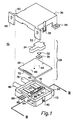
- the pressure transducer of the present invention is generally identified by reference numeral 10 and is shown in Figure 1 in an exploded perspective view.
- a housing 12 is provided which has a base surface 14 and a plurality of walls, 16, 18, 20 and 22, attached to the base surface 14 with a raised area 25 extending from the support boss 24.
- a support boss 24 is attached to the base surface 14.
- a pressure sensitive device identified by reference numeral 26 in Figure 1, comprises a ceramic plate 28, a buffer plate 30 and a silicon pressure sensor 32. These components of the pressure sensitive device 26 will be described in greater detail below.
- the pressure sensitive device 26 also comprises a cap 34 which is disposed on the ceramic plate 28 with the buffer plate 30 and the silicon pressure sensor 32 disposed between the cap and the ceramic plate.
- a cover 36 is attachable to the housing 12 by a plurality of snap acting connectors 38, or latches, which are shaped to receive tabs 40 in locking association therewith.
- the snap acting connector 38 is deformed slightly to permit the tab 40 to slip into the opening of the connector 38.
- the tab 40 moves entirely within the opening of the connector 38 and the connector snaps back into its normal position to capture the tab and retain the cover 36 on the housing.
- the cover 36 comprises a plurality of fastening devices that permit the cover 36 to be attached to an external device such as a printed circuit board.
- a first pair of feet, 50 and 52 is disposed at one end of the cover 36 to permit the pressure transducer to be mounted in one position relative to an external device.
- a second pair of feet, 54 and 56 is attached to another side of the cover 36 to permit the pressure transducer to be mounted in a different position relative to an external device such as a printed circuit board. Both pairs of feet are particularly located so that the housing 12 is in noncontact relation with the external device when the cover is mounted to the external device through the use of either pair of feet.
- the cover 36 is shaped to provide a clearance 60, which is shown more clearly in Figures 6 and 7, between a surface of the transducer and the contact surfaces of feet 50 and 52.
- the cover 36 is attached to the housing 12, the housing is supported by the cover in such a way that it does not contact the external device to which the transducer is attached.
- a similar technique is used when the other pair of feet, 54 and 56, is used to attach the transducer to an external device.
- FIG. 1 Also shown in Figure 1 is a plurality of terminals which are identified by reference numerals 64, 66 and 68. These terminals are rigidly attached to the housing 12 and extend through the housing to provide electrical communication between an external device and the ceramic plate 28 and, more particularly, the plurality of conductive pad 70 which are disposed on the ceramic plate in electrical communication with a plurality of components used to provide the amplification and compensation circuitry for the pressure transducer 10. As will be described in greater detail below, the terminals are not in physical contact with the ceramic plate but, instead, are disposed proximate the conductive pads 70 to permit flexible conductors to be attached to both the terminals and the pads to provide electrical communication therebetween. This technique permits electrical communication between the ceramic plate 28 and external devices without allowing stress to be transmitted from the terminals to the ceramic plate.
- a first means for connecting the pressure sensitive device 26 in fluid communication with a first region external to the transducer is partially identified by reference numeral 76.
- this first connecting means 76 or conduit, extends from a position external to the housing 12 through a portion of the housing and through a portion of the boss 24.
- this first conduit extends through an opening 80 in the boss 24 and a first opening 82 through the ceramic plate 28.
- the conduit continues through a cavity in the buffer plate 30 to a first side, or cavity side, of the silicon diaphragm in the pressure sensor 32.
- a second fluid connecting means 86, or conduit, is provided which extends through a second opening 88 in the boss 24 and a second opening 90 in the ceramic plate 28.
- This second conduit is connected in fluid communication with a region under the cap 34 which is above the pressure sensor 32 and in fluid communication with a second, or active, side of the diaphragm. Therefore, the two conduits, 76 and 86, are connected in fluid communication with opposite sides of the silicon diaphragm to permit the transducer to be operated as a differential pressure transducer.
- the transducer of the present invention can be applied in many different and alternative ways.
- a flexible adhesive material is used to provide this attachment.
- the flexibility, or deformability, of the adhesive provides a stress isolation member that inhibits the transmission of stress from the boss 24 and raised area 25 to the ceramic plate 28 while also inhibiting leakage from the first and second conduits at the region where the ceramic plate 28 joins the raised area 25 of the boss 24.
- the ceramic plate 28 is supported on the raised area 25 in a manner which prevents contact between the edges of the ceramic plate and the walls of the housing 12. This also inhibits stress from being transmitted from the walls of the housing to the ceramic plate. Only the central region of the plate is in physical contact with any portion of the housing.
- a flexible adhesive is used to attach the buffer plate 30 to the ceramic plate 28 and is also used to attach the pressure sensor 32 to the buffer plate 30. Therefore, between the boss 24 and the pressure sensor 32, three layers of flexible adhesive provide significant stress isolation between the stress sensitive diaphragm of the pressure sensor 32 and the housing 12. It is particularly important to inhibit stress from affecting the pressure sensor 32 in pressure transducers which are intended to measure very low magnitudes of pressure and in pressure transducers which utilize amplification and compensation circuitry within the transducer. If high magnitudes of pressure are to be measured by a transducer, relatively low magnitudes of stress, caused by either temperature changes or external forces, can be tolerated and appropriate compensation can be achieved.
- the ceramic plate 28 required to support the amplification and compensation circuitry introduces an additional potential for transmission of stresses in several ways.
- the coefficient of thermal expansion of the ceramic plate 28 is most likely to be significantly different than the coefficient of thermal expansion of the pressure sensor 32.
- its coefficient of thermal expansion is also likely to be significantly different than that of the housing 12. Stresses introduced into either the ceramic plate 28 or the pressure sensor 32 can cause inaccuracies in the output from the transducer.
- the terminals of the housing are required to be electrically connected to the pads 70, forces that are exerted on the terminals can be transferred through the ceramic plate to the pressure sensor if preventative measures, such as will be described below in conjunction with Figure 3, are not taken.
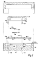
- FIG. 2 shows an exploded sectional view of the exploded assembly of Figure 1.
- the housing 12 is shown with walls 16 and 20 with terminal 66 attached to the housing 12 and extending through a portion of the housing.
- the ceramic plate 28 is shown with the first opening 82 and second opening 90 extending therethrough.
- the buffer plate 30 has a cavity 96 extending through it to provide fluid communication between opening 82 of the first conduit 76 and a first, or cavity, side 100 of the diaphragm of the pressure sensor 32.
- the diaphragm also has a second, or active, side 102 which, as will be described below, is disposed in fluid communication with the second conduit 86. It should be understood that the diaphragm of the pressure sensor 32 is extremely thin and responsive to changes in relative pressure between its two opposite surfaces.
- the diaphragm of the silicon sensor 32 typically has several piezoresistive components disposed on the diaphragm, usually by a diffusion process. Because of the extremely small dimensions of the diaphragm, the piezoresistive devices are not illustrated in Figure 2. However, these devices are very well known to those skilled in the art and are schematically illustrated in the prior art described above.
- the first side 101 of the ceramic plate 28 is disposed on a raised area 25 of the boss 24.
- the cap 34 is disposed on a second surface 104 of the ceramic plate 28 to enclose the pressure sensor 32 within a volume contained by surface 106 of the cap 34.
- the cap 34 has a first leg 108 and a second leg 110 which are shaped to be received through holes in the ceramic plate and in holes of the boss 24. As illustrated by the dashed lines in Figure 2, the first leg 108 extends through opening 112 into hole 114 and the second leg 110 extends through opening 116 into hole 118.
- the first and second legs in cooperation with the openings and holes described above, align the cap 34 and the ceramic plate 28 with the boss 24 in such a way that all of the holes and openings are properly positioned to form the first and second conduits described above.
- a fluid can pass from hole 80 in the boss 24 through opening 82 and cavity 96 to be in fluid communication with the first, or cavity, side 100 of the diaphragm.
- a fluid can pass from hole 88, through opening 90, to the region under the cap 34 defined by the inner surface 106 in fluid communication with the second, or active, side 102 of the diaphragm.
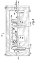
- Figure 3 shows the pressure transducer 10 of the present invention in an assembled arrangement. It should be understood that the assembled configuration of Figure 3 illustrates the components of Figure 2 arranged in cooperating association with each other.
- the illustration of Figure 3 shows the first conduit which comprises hole 80, opening 82 and cavity 96 which are all in fluid communication with the first, or cavity, side 100 of the diaphragm.
- Figure 3 also shows the second conduit which comprises hole 88, opening 90 and the region 120 which is defined by the surface 106 of the cap 34. This second conduit is in fluid communication with the second, or active, side 102 of the diaphragm.
- the terminal 66 is not in physical contact with the ceramic plate 28 but, instead, is spaced apart from the ceramic plate 28. This prevents the transfer of stress from the terminal 66 to the ceramic plate and the pressure sensor 32 which is disposed thereon. Electrical communication is provided by the flexible conductor 122 which is wirebonded to both of these components. Although the conductive pad 70 is not shown in Figure 3, it should be understood that the flexible conductor 122 is disposed in electrical communication with a preselected conductive pad. It should also be understood that although only one terminal 66 is shown in Figure 3, a preferred embodiment of the present invention incorporates a plurality of terminals which are each connected in electrical communication with selected ones of the conductive pad 70. Figure 3 also shows wirebonds 126 and 128 connected between the piezoresistive components on the diaphragm and the circuit components placed on the second surface of the ceramic plate 28.
- a space is provided between the edges of the ceramic plate 28 and the walls of the housing 12. This space is designated by reference numeral 130 in Figure 3. If the housing expands or contracts because of changes in temperature, space 130 prevents contact between the ceramic plate and the housing and therefore isolates the ceramic plate from stresses that could otherwise be transferred from the housing under these conditions. In addition, since the terminal 66 is not in physical contact with the ceramic plate 28, stresses can not be transferred from the terminals to the ceramic plate when external force is exerted on the terminals, either during a bending operation or during subsequent connection to external devices.
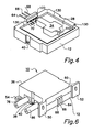
- FIG. 4 shows an assembled transducer made in accordance with the present invention but with the cover 36 removed.
- a space 130 is provided around the entire periphery of the ceramic plate 28 to separate the plate from the walls of the housing 12.
- the space surrounding the cap 34 on the surface of the ceramic plate is intended to contain a plurality of electronic components which comprise the circuitry necessary for amplification and compensation.
- Those electronic components are disposed on both surfaces of the ceramic plate and are connected in electrical communication with the conductive pads 70 and, through the flexible conductors such as that which is identified by reference numeral 122, to the terminals.
- the two sides of the ceramic plate are connected in electrical communication with each other by conductive paths extending through the plate.
- the total support of the pressure sensitive device 26, which comprises the ceramic plate 28 and the cap 34, is provided by the boss 24 along a central region underneath the ceramic plate.
- the boss is disposed beneath the ceramic plate along an alignment that extends from directly below the second pin 110 of the cap 34 toward the terminals, ending beneath the conductive pad 70.
- the ceramic plate 28 extends in a cantilevered fashion, above the base surface 14 of the housing 12. Therefore, the vast majority of the ceramic plate 28 is in noncontact association with the remaining components of the housing. Therefore, it is significantly isolated from the transfer of stress from the other housing components.
- Figure 5 illustrates a portion of the ceramic plate 28, showing only the first opening 82 through the plate.
- the buffer plate 30 will be disposed on the second surface of the ceramic plate 28 with its cavity 96 aligned with the first opening 82.
- the pressure sensor 32 is disposed on the buffer plate 30 in such a manner that its diaphragm is disposed in fluid communication with both the cavity 96 and the first opening 82.
- a flexible adhesive 140 is disposed around the first opening 82 so that the buffer plate 30 is attached to the ceramic plate 28.
- the flexible adhesive 142 which can be the same material as adhesive 140, is disposed a surface of the buffer plate 30, around the cavity 96, so that the pressure sensor 32 can be attached to the upper surface of the buffer plate 30.
- the use of flexible adhesive, 140 and 142 performs two functions that are important to the present invention. First, it seals the components together in such a way that leaks in the first conduit are prevented. Secondly, the flexible nature of the adhesive permits relative movement between the attached components. In other words, expansion of the ceramic plate 28 can occur without causing stress to be transmitted to the buffer plate 30.
- the second surface 102, or active surface, of the diaphragm is illustrated as having a plurality of piezoresistive devices 150 disposed on it.
- the piezoresistive devices 150 are only shown schematically in Figure 5, it should be understood that alternative configurations of piezoresistive devices and alternative components can be used to perform the functions required for the operation of a pressure sensor.
- Figure 6 illustrates the pressure transducer 10 of the present invention in an assembled form with the cover 36 disposed on the housing 12.
- Figure 7 also shows another view of the pressure transducer 10 of the present invention with the cover 36 attached to the housing 12.
- the attachment between the cover 36 and the housing 12 is achieved through the association of the snap acting connectors 38 with the tabs 40 on two sides of the transducer.
- the recess 60 of both the cover 36 and the housing 12, located between feet 50 and 52 permits the transducer to be supported in noncontact relation with an external object to which the feet, 50 and 52, are attached.
- the separation between the transducer and the external object which is provided by the recess 60 further isolates the pressure transducer 10 from stresses which could originate in the external object.
- the recess 60 permits the transducer to be attached to external objects which are not completely flat and uniform without introducing stresses in the package.
- another recess 160 is provided between feet 54 and 56 on the major surface shown in Figure 7. Therefore, when feet 54 and 56 are used to attach the pressure transducer 10 to an external object, such as a printed circuit board, the recess 160 maintains the pressure transducer in noncontact association with that external object to isolate it from full contact with the external object and prevent stresses from being transmitted easily from the external object to the pressure transducer.
- the terminals, 64, 66 and 68 can extend from the housing in a solely perpendicular manner as illustrated in Figure 7 or, alternatively, the terminals can be bent at right angles to extend in parallel with their support side of the housing 12, as shown in Figure 6. It should further be understood that when the terminals are bent to form the configuration shown in Figure 6 the forces required to perform the bend in each terminal could be transferred through the housing wall to the ceramic plate if the ceramic plate was in direct physical contact with the terminals. However, the present invention separates the terminals from the ceramic plate and utilizes flexible electrical conductors to connect the two in electrical communication with each other. Therefore, the forces necessary to bend the terminals do not transmit stress through the terminals to the ceramic plate.
- the ceramic plate 28, or board comprises a double-sided, screen printed circuit with a plurality of surface mounted components attached to its surface.
- An exemplary showing of these components is provided in Figures 8 and 9.
- Figure 8 shows the first side 100 of the ceramic plate 28 with the openings 82, 90, 112 and 116 which have been described in detail above.
- the central region 180 of the first side 101 is identified by a rectangle in Figure 8 to illustrate the portion of the first side 101 which is placed in contact with the raised area 25 of the boss 24. All portions of the ceramic plate 28 outside the rectangle 180 are supported in a cantilevered manner in noncontact relation with all portions of the housing 12. It can be seen that a plurality of conductive paths and electronic component positions are shown in Figure 8.
- the circuit components of the amplification and compensation circuits are disposed on the ceramic plate 28. It should be understood that alternative configurations of the component locations and conductive paths are within the scope of the present invention.
- Figure 9 shows the second side 104 of the ceramic plate 28 with the openings 82, 90, 112 and 116 which have been described above in detail.
- Reference number 182 identifies the location of the cap 34 and reference number 184 identifies the location of the buffer plate 30 and reference number 185 identifies the location of the pressure sensor 32.
- the illustration of Figure 9 also shows a plurality of conductive paths and trimmable resistors of the amplification and compensation circuit. The trimmable resistors are accessible for testing and adjustment after the transducer 10 is completely assembled, but before the cover 36 is attached to the housing 12.
- Figures 8 and 9 demonstrate how the present invention provides a means for supporting the internal components of a pressure transducer in noncontact relation with a housing to minimize the transmission of stress and strain from the housing to the diaphragm of the pressure sensor.
- This overall structure provides numerous stress isolators between the pressure sensor diaphragm and the sources of both thermally and mechanically induced stress.
- the electrical circuit which comprises the plurality of mounted components is used to amplify and compensate the output of the pressure sensor 32.
- the amplification is necessary to provide an output signal that is significantly higher in magnitude than the relatively small signal provided directly by the sensor.
- the compensation circuitry is necessary to compensate for temperature variations which could affect the piezoresistive characteristics of the components disposed on the diaphragm.
- the thin silicon buffer plate 30 is provided with a cavity 96 in its center and is bonded to the ceramic plate with a layer of soft adhesive.
- the pressure sensor 32 is then bonded to the buffer plate with a soft, or flexible, adhesive.
- the electrical connection between the ceramic substrate and the pressure sensor is performed with gold wirebonds in a most preferred embodiment of the present invention.
- the plastic cap 34 is disposed over the pressure sensor and the buffer plate in order to protect the pressure sensor and the wirebonds and also to create a sealed pressure chamber 120 around the upper surface of the pressure sensor 32.
- the use of the cap 34 to make the top pressure seal permits access to various test points on the second surface of the ceramic plate which are needed for differential pressure and temperature testing prior to the placement of the cover 36 on the housing 12.
- the cap 34 is provided with the two pins, 108 and 110, which pass through the holes, 112 and 116, in the ceramic plate 28 and into holes, 114 and 118, in the boss 24 of the housing.
- the use of these pins serves to align the ceramic plate in the housing and with the pressure responsive components on the ceramic plate.
- the pressure device 26, which comprises the ceramic plate 28, the buffer plate 30, the pressure sensor 32 and the cap 34 is then bonded to the raised area 25 of the support boss 24 through the use of a flexible adhesive.
- the two protruding ports shown in the figures permit the first and second conduits, 76 and 86, to be connected to pressure regions external to the housing.
- One port is connected to the first side, or cavity side, of the pressure sensor diaphragm and the other port is connected to the second side, or active side, of the diaphragm.
- the present invention is configured as shown in Figure 4, without the cover 36, all necessary sensitivity, zero offset and temperature compensation perimeters can be adjusted and tested because the components on the upper side of the ceramic plate 28 are readily accessible. After this adjustment and testing is complete, electrical connections are made between the terminals, 64, 66 68 and the conductive pads. After these connections are complete, through the use of flexible conductors 122, the cap 36 is snapped onto the housing 12.
- the present invention provides a pressure transducer which is of a relatively small size and which is durable and has a high sensitivity to pressure with a low amplifier gain.
- the pressure transducer exhibits a high accuracy with a low sensitivity to stress and permits mounting to external objects in various configurations. Because of the high sensitivity of the silicon pressure sensor used in the present invention, one of the most important features is its low sensitivity to stress.
- the characteristics described above combine to isolate the pressure sensor from virtually all sources of stress transmission. For example, the flexible electrical connections between the terminals and the conductive pads of the ceramic plate permit no stress transmission from the terminals to the pressure sensor.
- the pressure sensor die is also isolated from the ceramic plate by the buffer plate which is positioned between the two with the three components being attached together with a soft flexible adhesive.
- the pressure sensor die is located on the ceramic directly above the location where the ceramic is attached to the boss or supporting rib in the housing.
- the supporting rib, or boss is not connected to the side walls of the housing and therefore provides additional stress isolation between the pressure sensor and the housing.
- the ceramic plate is attached to the boss with a soft flexible adhesive to mechanically connect the ceramic to the housing as well as to maintain a pressure seal around the components which comprise the conduits.
- the clearance around the edges of the ceramic plate between the ceramic and the housing permits the housing walls to deform substantially without affecting the position of the ceramic plate.
- the mounting features comprising the feet are included as part of the cover instead of the housing. Therefore, after the cover is snapped onto the housing, the housing is disposed from any external device to which the cover is attached. This further isolates the housing from the external device to prevent stresses from being transmitted to the housing.
- the use of the snap acting contacts to attach the cover to the housing provides an additional isolation to the transmission of stress between the cover and the housing.
Landscapes
- Physics & Mathematics (AREA)
- General Physics & Mathematics (AREA)
- Measuring Fluid Pressure (AREA)
Abstract
Claims (12)
- Transducteur de pression comprenantun boîtier (12) possédant une surface de base (14), à laquelle une pluralité de parois (16,18,20,22) sont fixées;un bossage de support (24) situé sur ladite surface de base (14);un dispositif de détection de pression (26) destiné à être fixé audit bossage de support (24), ledit bossage de support (24) étant en contact avec une partie centrale d'une première surface du dispositif de détection de pression (26), de manière à supporter ledit dispositif sensible à la pression (26) selon une association, sans contact, avec ladite pluralité de parois (16,18,20,22);des premiers moyens (76) pour raccorder ledit dispositif sensible à la pression (26), selon une liaison fluidique, à une première région située à l'extérieur dudit boîtier (12);une pluralité de bornes électriquement conductrices (64,66,68) destinées à être fixées rigidement audit boîtier (12) et s'étendant depuis une première position proche dudit dispositif de détection de pression (26) à une seconde position située à l'extérieur dudit boîtier (12); etun capot (36) destiné à être fixé audit boîtier (12) ;le transducteur étant caractérisé en ce que ledit dispositif de détection de pression (26) comprend un élément céramique (28) possédant un circuit d'amplification et de compensation situé sur une surface de l'élément céramique qui est distante du bossage de support, l'élément céramique s'étendant, selon une disposition en porte-à-faux, au-dessus de la surface de base du boîtier, un capteur de pression (32) destiné à être placé sur ledit élément céramique (28) et un capuchon (34) destiné à être placé sur, et à former une chambre étanche avec, ladite surface dudit élément céramique (28), ledit élément de pression (32) étant disposé entre ledit capuchon et ledit élément céramique.
- Transducteur selon la revendication 1, caractérisé en ce que ledit dispositif sensible à la pression (26) comporte en outre une plaque intercalaire disposée entre ladite seconde surface et ledit capteur de pression (32).
- Transducteur selon la revendication 2, caractérisé en ce que ladite plaque intermédiaire est fixée à l'élément céramique (28) à l'aide d'un adhésif flexible, ledit capteur de pression (32) est fixé à ladite plaque intercalaire avec un adhésif flexible et ledit élément céramique (28) est fixé audit bossage de support (24) avec un adhésif flexible.
- Transducteur selon l'une quelconque des revendications précédentes, caractérisé en ce que ledit capteur de pression (32) comporte un diaphragme placé en communication fluidique avec lesdits moyens de raccordement.
- Transducteur selon l'une quelconque des revendications précédentes, caractérisé par des conducteurs électriques flexibles raccordés selon une liaison électrique entre lesdites bornes (64,66,68) et ledit élément céramique (28).
- Transducteur selon l'une quelconque des revendications précédentes, caractérisé en ce que lesdits premiers moyens de raccordement sont raccordés, selon une liaison fluidique, à un premier côté dudit diaphragme dudit capteur de pression (32).
- Transducteur selon la revendication 6, caractérisé par des seconds moyens pour raccorder un second côté dudit diaphragme dudit capteur de pression (32) selon une liaison fluidique avec une seconde région située à l'extérieur dudit boîtier (12).
- Transducteur selon la revendication 7, caractérisé en ce que lesdits premiers moyens de raccordement comprennent une première ouverture qui traverse ledit élément céramique (28) en étant reliée selon une liaison fluidique à une cavité de ladite plaque intercalaire et audit premier côté dudit diaphragme dudit capteur de pression (32), et lesdits seconds moyens de raccordement (86) comprennent une seconde ouverture qui traverse ledit élément céramique (28) en étant en liaison fluidique avec ledit second côté dudit diaphragme dudit capteur de pression (32).
- Transducteur selon l'une quelconque des revendications précédentes, caractérisé par des conducteurs électriques flexibles réalisés en or.
- Transducteur selon l'une quelconque des revendications précédentes, caractérisé en ce que ledit capot (36) comprend des premiers moyens pour fixer ledit transducteur à un objet, lesdits premiers moyens de fixation étant conformés de manière à supporter ledit boîtier (12) selon une association, sans contact, avec ledit objet.
- Transducteur selon la revendication 10, caractérisé en ce que ledit capot (36) comprend en outre des seconds moyens pour fixer ledit transducteur audit objet, lesdits seconds moyens de fixation étant conformés de manière à supporter ledit boîtier (12) selon une association, sans contact, avec ledit objet.
- Transducteur selon l'une quelconque des revendications précédentes, caractérisé en ce que ledit capot (36) et ledit boîtier (12) sont fixés conjointement, de façon amovible, à l'aide d'une pluralité de connecteurs à encliquetage.
Applications Claiming Priority (3)
| Application Number | Priority Date | Filing Date | Title |
|---|---|---|---|
| US07/798,476 US5257547A (en) | 1991-11-26 | 1991-11-26 | Amplified pressure transducer |
| US798476 | 1991-11-26 | ||
| PCT/US1992/010441 WO1993011414A1 (fr) | 1991-11-26 | 1992-11-25 | Transducteur de pression amplifie |
Publications (2)
| Publication Number | Publication Date |
|---|---|
| EP0614522A1 EP0614522A1 (fr) | 1994-09-14 |
| EP0614522B1 true EP0614522B1 (fr) | 1996-03-27 |
Family
ID=25173500
Family Applications (1)
| Application Number | Title | Priority Date | Filing Date |
|---|---|---|---|
| EP93900835A Expired - Lifetime EP0614522B1 (fr) | 1991-11-26 | 1992-11-25 | Transducteur de pression amplifie |
Country Status (5)
| Country | Link |
|---|---|
| US (1) | US5257547A (fr) |
| EP (1) | EP0614522B1 (fr) |
| JP (1) | JPH07500915A (fr) |
| DE (1) | DE69209519T2 (fr) |
| WO (1) | WO1993011414A1 (fr) |
Families Citing this family (74)
| Publication number | Priority date | Publication date | Assignee | Title |
|---|---|---|---|---|
| US5345823A (en) * | 1991-11-12 | 1994-09-13 | Texas Instruments Incorporated | Accelerometer |
| US5868678A (en) | 1993-06-30 | 1999-02-09 | Medex, Inc. | Two-part medical pressure transducer with diaphragm stand-offs |
| CA2224428C (fr) | 1993-06-30 | 2005-05-24 | Medex, Inc. | Capteur de pression medical avec composants coulissants |
| US5520054A (en) * | 1994-03-29 | 1996-05-28 | Rosemount Inc. | Increased wall thickness for robust bond for micromachined sensor |
| US5454270A (en) * | 1994-06-06 | 1995-10-03 | Motorola, Inc. | Hermetically sealed pressure sensor and method thereof |
| US5438877A (en) * | 1994-06-13 | 1995-08-08 | Motorola, Inc. | Pressure sensor package for reducing stress-induced measurement error |
| US5412994A (en) * | 1994-06-14 | 1995-05-09 | Cook; James D. | Offset pressure sensor |
| US5410916A (en) * | 1994-06-24 | 1995-05-02 | Honeywell Inc. | Flowthrough pressure sensor |
| US5459351A (en) * | 1994-06-29 | 1995-10-17 | Honeywell Inc. | Apparatus for mounting an absolute pressure sensor |
| JPH08233848A (ja) * | 1995-02-28 | 1996-09-13 | Mitsubishi Electric Corp | 半導体センサ |
| JP3394835B2 (ja) * | 1995-03-20 | 2003-04-07 | 株式会社キャットアイ | 部品取付装置 |
| WO1996034265A1 (fr) * | 1995-04-28 | 1996-10-31 | Rosemount Inc. | Ensemble de montage pour transmetteur de pression |
| JP3476199B2 (ja) * | 1995-04-28 | 2003-12-10 | ローズマウント インコーポレイテッド | 高圧隔離マウント組立体を有する圧力トランスミッタ |
| US5629486A (en) * | 1996-01-25 | 1997-05-13 | Delco Electronics Corporation | Pressure sensor apparatus with integrated circuit mounted thereon |
| US5802912A (en) * | 1996-01-25 | 1998-09-08 | Delco Electronics Corporation | Electrical terminal apparatus |
| DE19612964A1 (de) * | 1996-04-01 | 1997-10-02 | Bosch Gmbh Robert | Drucksensor und Verfahren zur Herstellung eines Drucksensors |
| JPH10104101A (ja) * | 1996-10-02 | 1998-04-24 | Mitsubishi Electric Corp | 半導体圧力センサ |
| US5684253A (en) * | 1997-01-08 | 1997-11-04 | Honeywell Inc. | Differential pressure sensor with stress reducing pressure balancing means |
| DE19711939A1 (de) * | 1997-03-21 | 1998-09-24 | Bosch Gmbh Robert | Vorrichtung zur Erfassung des Drucks und der Temperatur im Saugrohr einer Brennkraftmaschine |
| US5945605A (en) * | 1997-11-19 | 1999-08-31 | Sensym, Inc. | Sensor assembly with sensor boss mounted on substrate |
| DE19808248A1 (de) * | 1998-02-27 | 1999-09-02 | Pierburg Ag | Meßvorrichtung zur Messung der Masse eines strömenden Mediums |
| JP3452835B2 (ja) * | 1999-05-28 | 2003-10-06 | 三菱電機株式会社 | 圧力センサ装置 |
| JP4281178B2 (ja) * | 1999-10-06 | 2009-06-17 | 株式会社デンソー | 半導体圧力センサ |
| US6227055B1 (en) * | 1999-11-01 | 2001-05-08 | Delphi Technologies, Inc. | Pressure sensor assembly with direct backside sensing |
| US6874377B2 (en) * | 1999-11-10 | 2005-04-05 | Honeywell International Inc. | Sensor package for flush mounting of a sensor |
| US6883874B2 (en) | 2000-09-14 | 2005-04-26 | New York Air Brake Corporation | Pressure sensor module |
| US8623709B1 (en) | 2000-11-28 | 2014-01-07 | Knowles Electronics, Llc | Methods of manufacture of top port surface mount silicon condenser microphone packages |
| US7439616B2 (en) * | 2000-11-28 | 2008-10-21 | Knowles Electronics, Llc | Miniature silicon condenser microphone |
| US7166910B2 (en) | 2000-11-28 | 2007-01-23 | Knowles Electronics Llc | Miniature silicon condenser microphone |
| US7434305B2 (en) | 2000-11-28 | 2008-10-14 | Knowles Electronics, Llc. | Method of manufacturing a microphone |
| JP4801274B2 (ja) * | 2001-03-29 | 2011-10-26 | 本田技研工業株式会社 | 圧力センサを内蔵した制御箱 |
| DE10223357A1 (de) * | 2002-05-25 | 2003-12-04 | Bosch Gmbh Robert | Vorrichtung zur Druckmessung |
| US7788048B2 (en) * | 2003-04-24 | 2010-08-31 | Hewlett-Packard Development Company, L.P. | Apparatus and method for integrating a fuel supply and a fuel level sensing pressure sensor |
| DE10322017B8 (de) * | 2003-05-16 | 2005-02-24 | Sitronic Gesellschaft für elektrotechnische Ausrüstung mbH. & Co. KG | Sensoreinheit |
| US7024937B2 (en) * | 2003-12-03 | 2006-04-11 | Honeywell International Inc. | Isolated pressure transducer |
| US7191660B2 (en) * | 2004-04-15 | 2007-03-20 | Davidson Instruments Inc. | Flame shield for high temperature pressure transducer |
| DE102005008512B4 (de) | 2005-02-24 | 2016-06-23 | Epcos Ag | Elektrisches Modul mit einem MEMS-Mikrofon |
| DE102005008511B4 (de) | 2005-02-24 | 2019-09-12 | Tdk Corporation | MEMS-Mikrofon |
| US7628309B1 (en) * | 2005-05-03 | 2009-12-08 | Rosemount Aerospace Inc. | Transient liquid phase eutectic bonding |
| US7538401B2 (en) * | 2005-05-03 | 2009-05-26 | Rosemount Aerospace Inc. | Transducer for use in harsh environments |
| US20070013014A1 (en) * | 2005-05-03 | 2007-01-18 | Shuwen Guo | High temperature resistant solid state pressure sensor |
| DE102005053765B4 (de) | 2005-11-10 | 2016-04-14 | Epcos Ag | MEMS-Package und Verfahren zur Herstellung |
| DE102005053767B4 (de) | 2005-11-10 | 2014-10-30 | Epcos Ag | MEMS-Mikrofon, Verfahren zur Herstellung und Verfahren zum Einbau |
| EP1870687B1 (fr) | 2006-06-23 | 2012-09-12 | STMicroelectronics Srl | Assemblage d'un petit dispositif intégré facilitant la connection fluidique aux zones dudit dispositif |
| JP2008088937A (ja) | 2006-10-04 | 2008-04-17 | Mitsubishi Electric Corp | 検出装置及びエンジン制御装置 |
| US20080217709A1 (en) * | 2007-03-07 | 2008-09-11 | Knowles Electronics, Llc | Mems package having at least one port and manufacturing method thereof |
| US7788981B2 (en) * | 2007-03-16 | 2010-09-07 | Csem Centre Suisse D'electronique Et De Microtechnique Sa - Recherche Et Developpement | Pressure measurement device and system, and method for manufacturing and using the same |
| FR2917494B1 (fr) | 2007-06-12 | 2009-08-28 | Siemens Vdo Automotive Sas | Dispositif de maintien d'un capteur |
| US8994528B2 (en) * | 2007-06-15 | 2015-03-31 | Board Of Regents, The University Of Texas System | Thin flexible sensor |
| JP5355867B2 (ja) * | 2007-07-10 | 2013-11-27 | ローム株式会社 | 集積回路素子 |
| US7647835B2 (en) * | 2007-09-19 | 2010-01-19 | Honeywell International Inc. | Pressure sensor stress isolation pedestal |
| DE102007056284A1 (de) * | 2007-11-22 | 2009-05-28 | Continental Automotive Gmbh | Drucksensor |
| US8297125B2 (en) * | 2008-05-23 | 2012-10-30 | Honeywell International Inc. | Media isolated differential pressure sensor with cap |
| US8230745B2 (en) * | 2008-11-19 | 2012-07-31 | Honeywell International Inc. | Wet/wet differential pressure sensor based on microelectronic packaging process |
| US8322225B2 (en) * | 2009-07-10 | 2012-12-04 | Honeywell International Inc. | Sensor package assembly having an unconstrained sense die |
| US8082797B2 (en) * | 2009-11-11 | 2011-12-27 | Honeywell International Inc. | Pressure sensor assembly |
| US8230743B2 (en) | 2010-08-23 | 2012-07-31 | Honeywell International Inc. | Pressure sensor |
| US9021689B2 (en) | 2011-06-02 | 2015-05-05 | Freescale Semiconductor, Inc. | Method of making a dual port pressure sensor |
| US8307714B1 (en) * | 2011-06-02 | 2012-11-13 | Freescale Semiconductor, Inc. | Dual port pressure sensor |
| US8770034B2 (en) * | 2011-09-06 | 2014-07-08 | Honeywell International Inc. | Packaged sensor with multiple sensors elements |
| USD672261S1 (en) * | 2011-10-13 | 2012-12-11 | Fujikura Ltd. | Pressure sensor |
| EP2774390A4 (fr) | 2011-11-04 | 2015-07-22 | Knowles Electronics Llc | Membrane diélectrique intégrée en vue de servir de barrière dans un dispositif acoustique, et procédé pour sa fabrication |
| US9003897B2 (en) | 2012-05-10 | 2015-04-14 | Honeywell International Inc. | Temperature compensated force sensor |
| US9078063B2 (en) | 2012-08-10 | 2015-07-07 | Knowles Electronics, Llc | Microphone assembly with barrier to prevent contaminant infiltration |
| DE102013106353B4 (de) * | 2013-06-18 | 2018-06-28 | Tdk Corporation | Verfahren zum Aufbringen einer strukturierten Beschichtung auf ein Bauelement |
| JP6233507B2 (ja) * | 2014-05-15 | 2017-11-22 | 富士電機株式会社 | パワー半導体モジュールおよび複合モジュール |
| US10160636B2 (en) * | 2015-01-23 | 2018-12-25 | Mitsubishi Electric Corporation | Ceramic substrate, bonded body, module, and method for manufacturing ceramic substrate |
| US9794661B2 (en) | 2015-08-07 | 2017-10-17 | Knowles Electronics, Llc | Ingress protection for reducing particle infiltration into acoustic chamber of a MEMS microphone package |
| DE102016200699B4 (de) * | 2016-01-20 | 2025-12-04 | Robert Bosch Gmbh | Herstellungsverfahren für eine Detektionsvorrichtung und Detektionsvorrichtungen |
| US10942079B2 (en) * | 2018-03-29 | 2021-03-09 | Veoneer Us Inc. | Rectangular snap fit pressure sensor unit |
| US20200031661A1 (en) * | 2018-07-24 | 2020-01-30 | Invensense, Inc. | Liquid proof pressure sensor |
| US11225409B2 (en) | 2018-09-17 | 2022-01-18 | Invensense, Inc. | Sensor with integrated heater |
| WO2021095504A1 (fr) * | 2019-11-14 | 2021-05-20 | 日立Astemo株式会社 | Dispositif de détection de quantité physique |
| WO2023079883A1 (fr) * | 2021-11-05 | 2023-05-11 | 株式会社日立ハイテク | Capteur de pression et dispositif de distribution |
Family Cites Families (13)
| Publication number | Priority date | Publication date | Assignee | Title |
|---|---|---|---|---|
| FR2392323A1 (fr) * | 1977-05-23 | 1978-12-22 | Cibie Projecteurs | Nouveau projecteur d'automobile a ouverture rectangulaire |
| JPS5524423A (en) * | 1978-08-10 | 1980-02-21 | Nissan Motor Co Ltd | Semiconductor pressure sensor |
| JPS5937716Y2 (ja) * | 1979-01-31 | 1984-10-19 | 日産自動車株式会社 | 半導体差圧センサ |
| US4295117A (en) * | 1980-09-11 | 1981-10-13 | General Motors Corporation | Pressure sensor assembly |
| US4333349A (en) * | 1980-10-06 | 1982-06-08 | Kulite Semiconductor Products, Inc. | Binary balancing apparatus for semiconductor transducer structures |
| FI81911C (fi) * | 1987-12-07 | 1990-12-10 | Vaisala Oy | Trycksaendare. |
| US4797007A (en) * | 1987-12-18 | 1989-01-10 | Emhart Industries, Inc. | Temperature and line pressure probe |
| US4850227A (en) * | 1987-12-22 | 1989-07-25 | Delco Electronics Corporation | Pressure sensor and method of fabrication thereof |
| US4879903A (en) * | 1988-09-02 | 1989-11-14 | Nova Sensor | Three part low cost sensor housing |
| JPH02291838A (ja) * | 1989-05-02 | 1990-12-03 | Nec Corp | ディスポーザブル血圧トランスデューサ |
| US5134887A (en) * | 1989-09-22 | 1992-08-04 | Bell Robert L | Pressure sensors |
| DE3937522A1 (de) * | 1989-11-10 | 1991-05-16 | Texas Instruments Deutschland | Mit einem traegerelement verbundener halbleiter-drucksensor |
| JPH0465643A (ja) * | 1990-07-05 | 1992-03-02 | Mitsubishi Electric Corp | 半導体圧力センサ及びその製造方法 |
-
1991
- 1991-11-26 US US07/798,476 patent/US5257547A/en not_active Expired - Fee Related
-
1992
- 1992-11-25 WO PCT/US1992/010441 patent/WO1993011414A1/fr not_active Ceased
- 1992-11-25 EP EP93900835A patent/EP0614522B1/fr not_active Expired - Lifetime
- 1992-11-25 JP JP5510353A patent/JPH07500915A/ja active Pending
- 1992-11-25 DE DE69209519T patent/DE69209519T2/de not_active Expired - Fee Related
Also Published As
| Publication number | Publication date |
|---|---|
| DE69209519D1 (de) | 1996-05-02 |
| JPH07500915A (ja) | 1995-01-26 |
| EP0614522A1 (fr) | 1994-09-14 |
| DE69209519T2 (de) | 1996-10-31 |
| US5257547A (en) | 1993-11-02 |
| WO1993011414A1 (fr) | 1993-06-10 |
Similar Documents
| Publication | Publication Date | Title |
|---|---|---|
| EP0614522B1 (fr) | Transducteur de pression amplifie | |
| US5581038A (en) | Pressure measurement apparatus having a reverse mounted transducer and overpressure guard | |
| US5351550A (en) | Pressure sensor adapted for use with a component carrier | |
| US5684253A (en) | Differential pressure sensor with stress reducing pressure balancing means | |
| US6023978A (en) | Pressure transducer with error compensation from cross-coupling outputs of two sensors | |
| US4658651A (en) | Wheatstone bridge-type transducers with reduced thermal shift | |
| US5086777A (en) | Small-sized disposable pressure transducer apparatus with a temperature compensating circuit disposed adjacent a passageway coupled with a catheter | |
| US5412994A (en) | Offset pressure sensor | |
| US6272928B1 (en) | Hermetically sealed absolute and differential pressure transducer | |
| US7726197B2 (en) | Force sensor package and method of forming same | |
| US5522266A (en) | Low cost pressure transducer particularly for medical applications | |
| US4295117A (en) | Pressure sensor assembly | |
| EP0543430B1 (fr) | Palpeur de pression et méthode pour son assemblage | |
| US6986285B2 (en) | Pressure sensor and a rocket engine incorporating it | |
| EP0545319B1 (fr) | Capteur de pression à sémi-conducteurs comportant une structure avec deux diaphragmes | |
| CN108072487A (zh) | 校正压力传感器的方法和设备 | |
| HU183665B (en) | Semiconductor diaphragm, mechano-electric converter and dynamometer cell of semiconductor | |
| WO2007078748A2 (fr) | Modele de detecteur de pression differentielle amplifiee en conditions humides/humides base sur la technologie du silicium piezoresistif | |
| US3930412A (en) | Electrically scanned pressure transducer configurations | |
| EP0049955A1 (fr) | Capteur de pression à deux cavités | |
| CA1252646A (fr) | Transducteur de mesure | |
| US3900811A (en) | Economical pressure transducer assemblies, methods of fabricating and mounting the same | |
| JP3607420B2 (ja) | ドライタイプ圧力検出装置 | |
| JPH02196938A (ja) | 圧力センサ | |
| JP4244372B2 (ja) | 半導体センサ装置 |
Legal Events
| Date | Code | Title | Description |
|---|---|---|---|
| PUAI | Public reference made under article 153(3) epc to a published international application that has entered the european phase |
Free format text: ORIGINAL CODE: 0009012 |
|
| 17P | Request for examination filed |
Effective date: 19940524 |
|
| AK | Designated contracting states |
Kind code of ref document: A1 Designated state(s): DE FR GB |
|
| 17Q | First examination report despatched |
Effective date: 19940913 |
|
| GRAA | (expected) grant |
Free format text: ORIGINAL CODE: 0009210 |
|
| AK | Designated contracting states |
Kind code of ref document: B1 Designated state(s): DE FR GB |
|
| REF | Corresponds to: |
Ref document number: 69209519 Country of ref document: DE Date of ref document: 19960502 |
|
| ET | Fr: translation filed | ||
| PLBE | No opposition filed within time limit |
Free format text: ORIGINAL CODE: 0009261 |
|
| STAA | Information on the status of an ep patent application or granted ep patent |
Free format text: STATUS: NO OPPOSITION FILED WITHIN TIME LIMIT |
|
| 26N | No opposition filed | ||
| PGFP | Annual fee paid to national office [announced via postgrant information from national office to epo] |
Ref country code: FR Payment date: 19981030 Year of fee payment: 7 |
|
| PGFP | Annual fee paid to national office [announced via postgrant information from national office to epo] |
Ref country code: GB Payment date: 19981102 Year of fee payment: 7 |
|
| PGFP | Annual fee paid to national office [announced via postgrant information from national office to epo] |
Ref country code: DE Payment date: 19981103 Year of fee payment: 7 |
|
| PG25 | Lapsed in a contracting state [announced via postgrant information from national office to epo] |
Ref country code: GB Free format text: LAPSE BECAUSE OF NON-PAYMENT OF DUE FEES Effective date: 19991125 |
|
| GBPC | Gb: european patent ceased through non-payment of renewal fee |
Effective date: 19991125 |
|
| PG25 | Lapsed in a contracting state [announced via postgrant information from national office to epo] |
Ref country code: FR Free format text: LAPSE BECAUSE OF NON-PAYMENT OF DUE FEES Effective date: 20000731 |
|
| PG25 | Lapsed in a contracting state [announced via postgrant information from national office to epo] |
Ref country code: DE Free format text: LAPSE BECAUSE OF NON-PAYMENT OF DUE FEES Effective date: 20000901 |
|
| REG | Reference to a national code |
Ref country code: FR Ref legal event code: ST |