EP0614638A2 - Vorrichtung mit Unterteilungen für die geordnete Präsentation von Schachteln und Produktverpackungen - Google Patents
Vorrichtung mit Unterteilungen für die geordnete Präsentation von Schachteln und Produktverpackungen Download PDFInfo
- Publication number
- EP0614638A2 EP0614638A2 EP19940102748 EP94102748A EP0614638A2 EP 0614638 A2 EP0614638 A2 EP 0614638A2 EP 19940102748 EP19940102748 EP 19940102748 EP 94102748 A EP94102748 A EP 94102748A EP 0614638 A2 EP0614638 A2 EP 0614638A2
- Authority
- EP
- European Patent Office
- Prior art keywords
- elements
- sideboard
- holding device
- bar
- couple
- Prior art date
- Legal status (The legal status is an assumption and is not a legal conclusion. Google has not performed a legal analysis and makes no representation as to the accuracy of the status listed.)
- Withdrawn
Links
Images

Classifications
-
- A—HUMAN NECESSITIES
- A47—FURNITURE; DOMESTIC ARTICLES OR APPLIANCES; COFFEE MILLS; SPICE MILLS; SUCTION CLEANERS IN GENERAL
- A47F—SPECIAL FURNITURE, FITTINGS, OR ACCESSORIES FOR SHOPS, STOREHOUSES, BARS, RESTAURANTS OR THE LIKE; PAYING COUNTERS
- A47F1/00—Racks for dispensing merchandise; Containers for dispensing merchandise
- A47F1/04—Racks or containers with arrangements for dispensing articles, e.g. by means of gravity or springs
- A47F1/12—Racks or containers with arrangements for dispensing articles, e.g. by means of gravity or springs dispensing from the side of an approximately horizontal stack
-
- A—HUMAN NECESSITIES
- A47—FURNITURE; DOMESTIC ARTICLES OR APPLIANCES; COFFEE MILLS; SPICE MILLS; SUCTION CLEANERS IN GENERAL
- A47F—SPECIAL FURNITURE, FITTINGS, OR ACCESSORIES FOR SHOPS, STOREHOUSES, BARS, RESTAURANTS OR THE LIKE; PAYING COUNTERS
- A47F5/00—Show stands, hangers, or shelves characterised by their constructional features
- A47F5/0043—Show shelves
- A47F5/005—Partitions therefore
Definitions
- This invention relates to an object-holding device, constituted by the horizontal combination of modular sectional elements, particularly suitable for supporting and displaying prismatic containers, such as boxes and various packages of miscellaneous products, such as for instance drug packages, toiletries and the like, as well as for supporting and displaying items having different shapes, such as vases from glass, plastic materials or other materials, bottles and the like.
- the problem of tidily displaying products that are contained in boxes, small bottles and packages of different type and size, particularly drugs, toiletries, perfumes, medicinal herbs, anf food in general is usually solved, in some cases, by laying out the packages side by side on the display surface (for instance, shop-windows, shelves and racks in general), in other cases, the packages of one only product or of several products are arranged on special trays, or the like, in order to keep them tidily arranged or placed side by side on the supporting surface.
- the packages of products to be displayed are arranged on multilevel displayers, often rotatory and/or orientatable, so as to permit the choice and taking of the products one wishes.
- an object of this invention is to provide an object-holding device so designed as to allow the presentation and/or display of the packages in a stable and tidy manner, whatever the size and shape of the individual packages may be, and independently on the fact that said packages contain different or equal products, and such as to allow an easy taking and replenishment of the empty spaces after each taking, without alterating the starting position of the sets of adjoining packages.
- Another object of the invention is to provide an object-holding device so designed as to be easily and quickly adaptable to the sizes and shapes of the packages and boxes to be displayed and to allow variations of the display capacity within wide limits, without having recourse to special tools.
- Still a further object of the invention is to provide an object-holding device of the aforementioned type, so designed at to be highly reliable and functional, realizable from various materials, of a limited overall dimensions and to very low costs.
- an object-holding device placeable on shelves, shop-windows and the like which device, according to this invention, comprises:
- a flat inclined element is provided, suitable to be used for possible inscriptions and/or words characterizing the products on display.
- Said flat inclined element is also a supporting element for an elongated longitudinal element constituting the plate, the support for a plate or a protection for same, so inserted as to bestridingly fit between the special longitudinal engagement projections realized before and behind said inclined flat element and parallel to the latter.
- Said elongated element is made from transparent plastic material bendable and/or flexible of a length equal to the length of said way or ways, and of a height equal or slightly greater or slightly shorter than the height of said inclined flat element.
- Said elongated element may be advantageously obtained, for instance, from a slab-element from flexible transparent material, provided with transversal back-not-ches, suitable to make posssible the bending of the slab according to the shape wished.
- said elongated element is advantageously utilized to highlight the inscriptions, the words and/or the pictures characterizing the products on display.
- the elongated element constituting a plate or a plate support or protection, as said, can be applied by glueing or the like on said inclined flat elements, or can be fitted between said inclined elements and the engagement protrusions, and ensures also a greater assembly stability between said bar-elements, allowing at the same time the presentation and/or display of the packages in a stable, tidy and elegant manner.
- the elements which constitute the object-holding device according to this invention are preferably made from rigid plastic material or the like, such as for instance polymethylmetacrilate, polyvynil chloride, polystyrene and the like.
- one or more magnetic elements are advantageously utilized, which are fixed to the lower face of said elements provided with sideboard if said shelves or the like are made from metal, or if they are made from different materials, suitable magnets or the like can be provided on said shelves or the like, in correspondence with said magnetic elements.
- said bar-elements provided with a sideboard are provided with one or more hollow support elements having preferably a rectangular section, suitable to support said elements and therefore the frame on shelves and the like, said hollow support elements being also suitable to contain and hold said magnetic elements and to keep them in place by embedding, adhesion or the like.
- bar-elements having the shape of substantially rectangular ledges, constituted by a bearing base and a vertical and longitudinal separation board centrally placed at 90°C relatively to said bearing base, which can be placed between said bar-elements provided with a sideboard and stably kept in the right position by adhesion of their bearing base on said base bar-elements, circumscribing in this way parallel ways, even of different width relatively to one another, suitable to support the products and/or the packages to be displayed to the public.
- said couple of bar-elements provided with a sideboard along one of their longitudinal sides comprises:
- Said elements are also provided with suitably spaced transversal notches, suitable to constitute as many stress raisers for the separation by bending and breaking of lengths of said elements, in order to adjust the dimensions of the structure to the dimensions of the shelves.
- these bar-extensions are also provided with a series of transversal notches, suitable to form engagements for the separation by bending and breaking of the protruding lengths of said extensions, once said first and said second elements have been positioned and fixed at the distance wished.
- each of said elements that should remain on sight are preferably realized according to an inclined plane and are also provided with a first strip bent by 90° towards the inside, as well as with a parallel counter-strip, opposite and spaced from said first strip, so as to create a space or groove inside which the edges of plates, labels and the like suitable to characterise the products on display can be slidingly introduced, which plates and the like are therefore kept in position, while being easily replaceable by simple unthreading.
- said couple of bar-elements provided with a sideboard along a longitudinal side comprises:
- said slab-elements have different sizes, allowing in this way to modify the distance between said first and said second element constituting said first couple, according to the shapes and sizes of the items to be displayed to the public.
- Said rectangular slab-elements are also provided, on their underface, of at least two strips of tape, positioned along the two opposite ends of said slab-elements which are to lay on said elongated bases and on said inclined plane front ends of said first and said second element.
- Said tape strips are also protected by means of paper strips or the like, suitable to be easily removed when said slab-elements are positioned on said first and said second element.
- said first and said second element are provided with one or more transversal notches realized on said sideboards, suitable to become as many stress raisers for the separation by cutting of lengths of said elements, in order to adjust the length of the object-holding device to the dimensions of the shelves.
- transversal notches are preferably "V"-shaped, so as to lend the structure also special aesthetic effects.
- said problem of keeping said object-holding device stable on shelves and the like can be advantageously solved by means of one or more nagnetic elements placed and fixed within said first and said second container, in correspondence of the lower face of said elongated bases and in such a way as to be flush with the lower edge of said sideboards and said downwards bent strips.
- said first and said second elemnd are preferably realized from heat-moulded plastic maerial, such as for instance polystyrene, polyvynil chloride and the like.
- Said slab-elements are advantageously realized from rigid plastic material, such as for instance polymethylmetacrilate, polyvynil chloride and the like.
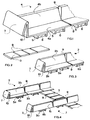
- Figs. 1 to 7 show a first embodiment of the invention
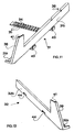
- Figs. 8 to 12 show a second embodiment of the invention
- Figs. 11 to 13 show still a third embodiment of the invention.
- Fig. 1 shows, in perspective view, the bar-element provided with a centrally placed vertical wall
- Fig. 2 shows, always in perspective view, the rectangular ledge-shaped bar-element
- Fig. 3 shows, always in perspective view, the bar-element provided with a sideboard
- Fig. 4 shows, always in perspective view, the couple constituted by the first and the second element associated among one another and kept stable by the rectangular ledge-shaped element.
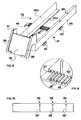
- Fig. 5 shows a plan of the transparent slab-element from plastic material, while Fig. 5' shows the same element viewed laterally along the d-d' line.
- Fig. 6 shows the section of a detail of a slab-element provided with a sideboard
- Fig. 7 shows the section of the element of Figs. 3 and 6, bestrided by the elongated element assembled on it.
- Fig. 8 shows a perspective view of a first element provided with a sideboard and provided with a bar-extension, connected to a second element, according to a second embodiment of the invention
- Fig. 9 shows, always in perspective view, the detail of the connection of said bar-extension with said second element
- Fig. 10 shows the plan of the detail of the transversal notches suitable to become as many stress raisers for the separation by bending and breaking of lengths of said elements
- Fig. 11 shows a perspetive view of said first element provided with the bar-extension
- Fig. 12 shows, always in perspective view, said second element.
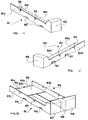
- Figs. 14 and 15 show, in perspective view, the first and the second elongated box-shapeded element, while Fig. 13 shows, always in perspective view, the first and the second element connected to one another and kept in the right position by two slab-elements, according to still a further embodiment of this invention.
- element 4 is constituted by a bearing base 4a and by a vertical wall 4b, placed at 90° and centrally positioned relatively to said base 4a.
- Three supporting hollow elements 5 are positioned on the lower face of said base 4a, suitable for housing and holding by adhesion the magnetic elements 6.
- an inclined flat element 7 is provided, suitable to carry possible inscriptions characterizing the products displayed, and suitable to constitute a supporting element for said elongated element 8, which is shown mounted on Fig. 7.
- Said element 4 is also provided with transversal notches 9, suitable to become as many stress raisers for the separation by bending and breaking of lengths of said element 4.
- Fig. 2 shows the rectangular ledge-shaped element 3, provided with transversal notches 9c, suitable to become as many stress raisers for the separation by bending and breaking of said element 3.
- Element 2 shown in perspective view on Fig. 3, is constituted by a bearing base 2a, a sideboard 2b placed at 90° along the longitudinal side of base 2a; besides, three support hollow elements 5a are positioned on the lower face of said base 2a, suitable for housing and holding by adhesion the magnetic elements 6a.
- an inclined flat element 7 is provided suitable to carry possibile inscriptions characterizing the products displayed and suitable to constitute a supporting element for said elongated element 8, shown assembled on Fig. 7.
- Said element 2 is also provided with transversal notches 9, suitable to become as many stress raisers for the separation by bending and breaking of lengths of said element 2.
- Element 1 shown on Fig. 4 connected to said element 2 to form a couple, is constituted by a bearing base 1a, not shown on the figure, a sideboard 1b placed at 90° along a longitudinal side of said base a and mirror-opposite to said sideboard b2 of said element 2.
- Two supporting hollow elements 5b suitable for housing and holding by adhesion the magnetic elements 6b, are positioned on the lower face of said base 1a.
- an inclined flat element 7 is provided, suitable to carry possible inscriptions characterizing the products displayed, and suitable to constitute a supporting element for said elongated element 8, shown assembled on Fig. 7.
- Said element 1 is also provided with transversal notches 9, suitable to become as many stress raisers for the separation by bending and breaking of lengths of said element 1.
- Said elements 1 and 2 which form said couple are kept at the distance wished and held in the right position by adhesion of a length of the lower faces of said bases 1a and 2a on the upper face of said element 3.
- the way provided with sideboards allows to shift the packages towards an end, usually the front one which is on sight, in order to improve the aesthetic appearance of the device even in the case of a way where there are empty spaces.
- the individual elements 1, 2 and 4 are provided with transversal notches 9 provided on sideboards 1b, 2b and 4b and on the bearing bases 1a, 2a and 4a, while element 3 is provided with transversal notches only. Said notches become as many stress raisers for the separation of element lengths by simple bending of the lengths to be removed in order to adjust the structure to the width and length of the bearing surface of same.
- the notches provided on sideboards 1b, 2b and 4b are preferably "V"-shaped, so as to lend the structure special aesthetic effects.
- elements 1, 2 and 4 which shall remain on sight when the structure is utilized, elements are applied for holding the packages which are constituted by a reverse "V"-arched wall or the like, wherein wall 10 is an end board and the inclined part 7 constitutes a surface useful for carrying inscriptions and/or words related to the characteristics and/or the price of the packages displayed.
- Fig. 5 is a plan of the slab-element from flexible transparent plastic material 8, provided with notches 12 which allow to perform the bending of element 8 according to the shape wished.
- Fig. 5' is a side view of the same slab-element 8, along the line d-d'.
- Fig. 6 shows the section of an element constituted by a reverse "V" arched wall or the like, shown also in perspective on Figs. 1, 3 and 4, provided with a vertical wall 10 and an inclined wall 7, which circumscribes on its external lower bearing surface end a "s" space suitable for housing the bent slab-element shown assembled on Fig. 7.
- element 31 is constituted by a rectangular section 31a provided (or inegrally realized) with a sideboard 31b placed at 90°, which runs all along the longitudinal side of said element 31.
- Said element 31 is also provided with a substantially rectangular bar-extension 34, fixed perpendicularly to the bearing base 31a of said element 31, and provided on its upper surface with a set of protruding prismatic elements 35, equispaced and parallel to one another.
- Said bar-extension is also provided with one or more transversal notches 45, suitable to become as many stress raisers for the separation by bending and breaking of the protruding lengths 46 of said extension, once elements 31 and 32 have been positioned and fixed at the distance wished.
- Said element 31 is also provided with transversal notches 36 and 36', respectively provided in sideboard 31a, suitable to become as many stress raisers for the separation by bending and breaking of lengths of said element 31, in order to adjust the overall dimensions of the product-holding device according to the needs.
- said element 31 is provided with one or more protruding hook-elements or the like, positioned on the external side of said sideboard 31b.
- Element 32 is constituted by a rectangular section 32a provided (or integrally realized) with a sideboard 32b placed at 90°, running all along a longitudinal side of said element 32 and such as to be mirror-opposite to said sideboard 31b of element 31.
- said element 32 is provided, on the lower face of its bearing base 32a, with a set of grooves 37, suitable for housing and embedding said raised elements 32 provided on the upper surface of said bar-extension 34, as shown in transparence on Fig. 8 and in detail on Fig. 9, in order to fix said element 32 at the distance wished relatively to element 31, forming a first couple and obtaing a stable structure.
- Said element 32 of said first couple is also provided with one or more notches 44, provided on the external side of said sideboard 32b, suitable for housing and holding the protruding elements, provided on element 31, of a second couple, allowing in this way to join two or more couples to one another, realizing in this way a modular device.
- each element 31 and 32 the ends which shall remain on sight, respectively indicated by 38 and 39, are realized according to an inclined plane and provided with a first strip bent at 90° towards the inside and by a counter-strip, parallel and so spaced from said first strip as to create a space 41, within which the edged of plates, labels and the like 42 can be slidingly iserted, as shown on Fig. 8, suitable to characterize the products on display; said plates 42 are therefore kept in position and are quickly and easily removable by simple unthreading.
- a longitudinal way creates on which one can stably insert containers or prismatic packages of various products; the stability of packages is ensured by the sideboards and the continuity of the flat parallel surfaces 31a and 32a of said elements 31 and 32.
- Said longitudinal way, circumscribed by the vertical sideboards 31 and 32 is suitable to hold not only box-shaped containers or prismatic packages as said, but also containers of various shapes such as jars, bottles, etc., providing possibly additional support elements placed on said parallel flat surfaces 31a and 32a of said elements 31 and 32 having a shape suitable for holding asymmetrical containers having irregular shapes.
- the individual elements are provided with stress raisers 36 and 45 and transversal notches 36' and 45, provided on sideboards 31b and 32 b, in flat sections 31a and 32a, and in bar-extensions 34. Said notches become as many stress raisers for the separation of lengths of said elements and said extensions by simple bending of the lengths to be removed in order to adjust the structure to the width and length of the bearing surface of same.
- stress raisers 36 and 45 provided in sideboards 31b and 32b and in extensions 34 are preferably "V"-shaped, so as to lend the structure also particular aesthetic effects.
- Fig. 14 shows in perspective view the first element 61 of hollow, elongated, box-like shape, integrally constituted by a flat elongated base 61a, an elongated sideboard 61b placed at 90° relatively to base 61a, and a downwards bent strip 61c.
- Said first element 61 is also provided with two hollow spaces 66 provided on the external face of the lateral sideboard 61b; the front end 63 of said element 61 is made according to an inlined place and is slightly protruding relatively to said sideboard 61b.
- Said element 61 is also provided with two transversal notches 65 provided on sideboard 61, suitable to become as many stress raisers by cutting of lengths of said element 61.
- Fig. 15 shows, in perspective view, the second hollow elongated box-shaped element 62 integrally constituted by a base 62a having also an elongated shape, a sideboards 62b placed at 90° relatively to said base 62a and mirror-opposing said sideboard 61b, a downwards bent strip 62c, placed at 90° relatively to said base 62a along the side opposite to said sideboard 62b.
- Element 62 is also provided with two protruding elements 67, positioned on the external face of said sideboard 62b and in correspondence with said hollow spaces 66 on sideboard 61b; besides, the front end 68 of said element 62 is made according to an inclined plane and its upper part is protruding relatively to sideboards 62b.
- Element 62 is also provided with two transversal notches 65 cut in sideboard 62, suitable to become as many stress raisers for the separation, by cutting, of lengths of said element 62.
- Fig. 13 shows, always in perspective view, elements 61 and 62 assembled to one another and held in position by means of two rectangular plate-elements 69 and 50; said plate-elements 69 and 50 are suitable to stably fasten elements 61 and 62 assembled to one another to form a first couple, by adhesion of the first element 69 on to the front faces 63 and 68 of said elements 61 and 62, as well as by adhesion of the second element 50 in flat position on a length of the upper faces of said elongated bases 61a and 62a of said elements 61 and 62.
- the hollow spaces 66 provided on sideboard 61b of element 61 making part of the first couple are suitable for housing and embedding the protruding elements provided on the second element of a second couple, allowing to assemble two or more couples among one another, circumscribing a plurality of parallel ways, suitable to support box-shaped containers and product of various kind.
Landscapes
- Details Of Rigid Or Semi-Rigid Containers (AREA)
Applications Claiming Priority (6)
| Application Number | Priority Date | Filing Date | Title |
|---|---|---|---|
| ITMI930185U | 1993-03-10 | ||
| IT93MI000184U IT229702Y1 (it) | 1993-03-10 | 1993-03-10 | Dispositivo porta prodotti ad elementi componibili, per la presentazio ne-esposizione ordinata di scatole e confezioni di prodotti in genere |
| IT93MI000183U IT229701Y1 (it) | 1993-03-10 | 1993-03-10 | Dispositivo porta prodotti ad elementi modulari e componibili |
| ITMI930184U | 1993-03-10 | ||
| ITMI930183U | 1993-03-10 | ||
| IT93MI000185U IT229703Y1 (it) | 1993-03-10 | 1993-03-10 | Dispositivo porta prodotti ad elementi componibili per la presentazion e-esposizione ordinata di scatole e confezioni di prodotti in genere |
Publications (1)
| Publication Number | Publication Date |
|---|---|
| EP0614638A2 true EP0614638A2 (de) | 1994-09-14 |
Family
ID=27274000
Family Applications (1)
| Application Number | Title | Priority Date | Filing Date |
|---|---|---|---|
| EP19940102748 Withdrawn EP0614638A2 (de) | 1993-03-10 | 1994-02-24 | Vorrichtung mit Unterteilungen für die geordnete Präsentation von Schachteln und Produktverpackungen |
Country Status (1)
| Country | Link |
|---|---|
| EP (1) | EP0614638A2 (de) |
Cited By (9)
| Publication number | Priority date | Publication date | Assignee | Title |
|---|---|---|---|---|
| FR2735669A1 (fr) * | 1995-06-20 | 1996-12-27 | Gosselin Plv | Structure modulaire pour l'amenagement d'une surface, notamment d'une etagere ou d'un tiroir |
| FR2746616A1 (fr) * | 1996-04-02 | 1997-10-03 | Hurez Bernard Paul | Couloirs de rangement et de presentation a geometries variables |
| FR2754157A1 (fr) * | 1996-10-04 | 1998-04-10 | Mbcg Soc | Nouveau dispositif de presentation pour flaconnages et les flaconnages ainsi presentes |
| FR2851441A1 (fr) * | 2003-02-26 | 2004-08-27 | Media 6 Gestion | Organe support de presentation de marchandises et dispositif de presentation pour la mise en oeuvre de tels organes |
| WO2004112550A1 (en) * | 2003-06-19 | 2004-12-29 | The Procter & Gamble Company | Shelf tray apparatus for absorbent articles packaged in flexible film |
| FR2868925A1 (fr) * | 2004-04-16 | 2005-10-21 | Media 6 Gestion Soc Par Action | Dispositif pour la presentation de marchandises et systeme de presentation et de separation de marchandises mettant en oeuvre un tel dispositif |
| FR2940031A1 (fr) * | 2008-12-22 | 2010-06-25 | Media 6 | Systeme de calage pour l'agencement ordonne de produits sur un presentoir, notamment de produits pre-charges |
| US9398817B2 (en) | 2010-12-29 | 2016-07-26 | Big Skies Limited | Apparatus for facing products |
| KR20230159761A (ko) * | 2022-05-13 | 2023-11-22 | 김학배 | 창문설치용 선반 |
-
1994
- 1994-02-24 EP EP19940102748 patent/EP0614638A2/de not_active Withdrawn
Cited By (10)
| Publication number | Priority date | Publication date | Assignee | Title |
|---|---|---|---|---|
| FR2735669A1 (fr) * | 1995-06-20 | 1996-12-27 | Gosselin Plv | Structure modulaire pour l'amenagement d'une surface, notamment d'une etagere ou d'un tiroir |
| FR2746616A1 (fr) * | 1996-04-02 | 1997-10-03 | Hurez Bernard Paul | Couloirs de rangement et de presentation a geometries variables |
| FR2754157A1 (fr) * | 1996-10-04 | 1998-04-10 | Mbcg Soc | Nouveau dispositif de presentation pour flaconnages et les flaconnages ainsi presentes |
| FR2851441A1 (fr) * | 2003-02-26 | 2004-08-27 | Media 6 Gestion | Organe support de presentation de marchandises et dispositif de presentation pour la mise en oeuvre de tels organes |
| WO2004112550A1 (en) * | 2003-06-19 | 2004-12-29 | The Procter & Gamble Company | Shelf tray apparatus for absorbent articles packaged in flexible film |
| US6889856B2 (en) | 2003-06-19 | 2005-05-10 | The Procter & Gamble Company | Shelf tray apparatus for absorbent articles packaged in flexible film |
| FR2868925A1 (fr) * | 2004-04-16 | 2005-10-21 | Media 6 Gestion Soc Par Action | Dispositif pour la presentation de marchandises et systeme de presentation et de separation de marchandises mettant en oeuvre un tel dispositif |
| FR2940031A1 (fr) * | 2008-12-22 | 2010-06-25 | Media 6 | Systeme de calage pour l'agencement ordonne de produits sur un presentoir, notamment de produits pre-charges |
| US9398817B2 (en) | 2010-12-29 | 2016-07-26 | Big Skies Limited | Apparatus for facing products |
| KR20230159761A (ko) * | 2022-05-13 | 2023-11-22 | 김학배 | 창문설치용 선반 |
Similar Documents
| Publication | Publication Date | Title |
|---|---|---|
| US4765492A (en) | Display assemblies for integrated modular store fixture system | |
| US6883671B2 (en) | Merchandise shipping and display system | |
| JP5798488B2 (ja) | 棚システム | |
| US4282975A (en) | Jewelry display tray | |
| US4550838A (en) | Modular display rack | |
| CA2810680C (en) | Bin-type display fixture | |
| US6006927A (en) | Paint chip display system | |
| ES2691714T5 (es) | Instalación de presentación, en particular para productos | |
| EP0614638A2 (de) | Vorrichtung mit Unterteilungen für die geordnete Präsentation von Schachteln und Produktverpackungen | |
| US20030034319A1 (en) | Apparatus for compartmentalizing a shelf | |
| US4175807A (en) | Modular constructional units for a combined storage bin and display assembly | |
| US4396237A (en) | Package displaying dispenser | |
| US5853091A (en) | Display frame/interlocking storage rack component | |
| US4006824A (en) | Display and dispensing stand | |
| DK0999773T3 (da) | Udstillingsstativ | |
| US6059113A (en) | Display package with corrugated insert | |
| US5322159A (en) | Hanging display improvement for nesting containers | |
| US6520339B1 (en) | Article storage assembly with an attached article display case | |
| US20060226100A1 (en) | Customizable display unit | |
| US5472100A (en) | Greeting card display rack | |
| JP3202118B2 (ja) | 商品陳列装置 | |
| US4897948A (en) | Display systems | |
| JPH049308Y2 (de) | ||
| KR200320551Y1 (ko) | 상품 진열 상자 | |
| US5216835A (en) | Floral display and transportation rack |
Legal Events
| Date | Code | Title | Description |
|---|---|---|---|
| PUAI | Public reference made under article 153(3) epc to a published international application that has entered the european phase |
Free format text: ORIGINAL CODE: 0009012 |
|
| AK | Designated contracting states |
Kind code of ref document: A2 Designated state(s): DE ES FR GB |
|
| STAA | Information on the status of an ep patent application or granted ep patent |
Free format text: STATUS: THE APPLICATION IS DEEMED TO BE WITHDRAWN |
|
| 18D | Application deemed to be withdrawn |
Effective date: 19960830 |