EP0614643A1 - Duschabtrennung - Google Patents
Duschabtrennung Download PDFInfo
- Publication number
- EP0614643A1 EP0614643A1 EP94102953A EP94102953A EP0614643A1 EP 0614643 A1 EP0614643 A1 EP 0614643A1 EP 94102953 A EP94102953 A EP 94102953A EP 94102953 A EP94102953 A EP 94102953A EP 0614643 A1 EP0614643 A1 EP 0614643A1
- Authority
- EP
- European Patent Office
- Prior art keywords
- groove
- sliding
- sliding door
- extension arm
- shower partition
- Prior art date
- Legal status (The legal status is an assumption and is not a legal conclusion. Google has not performed a legal analysis and makes no representation as to the accuracy of the status listed.)
- Granted
Links
Images
Classifications
-
- A—HUMAN NECESSITIES
- A47—FURNITURE; DOMESTIC ARTICLES OR APPLIANCES; COFFEE MILLS; SPICE MILLS; SUCTION CLEANERS IN GENERAL
- A47K—SANITARY EQUIPMENT; ACCESSORIES THEREFOR, e.g. TOILET ACCESSORIES
- A47K3/00—Baths; Showers; Appurtenances therefor
- A47K3/28—Showers or bathing douches
- A47K3/30—Screens or collapsible cabinets for showers or baths
- A47K3/34—Slidable screens
Definitions
- the present invention relates to a shower partition with a sliding door, which is formed from sliding door leaves, each having a surrounding frame, the upper and lower spar is slidably guided in horizontal rails.
- the sliding door which enables entry into the shower partition, consists of several sliding door leaves, which, when pushed together, lie one behind the other, with a view of the front, and when opened, they close the entrance.
- the horizontal profile rails and the spars forming the surrounding frames are usually hollow profiles made of an aluminum alloy.
- the critical areas are the facing surfaces of the horizontal profile rail and the spar of the surrounding frame. This area is practically inaccessible and therefore cannot be cleaned.
- the lower area is particularly to be cleaned, since normally no water penetrates into the upper area.
- the present invention has for its object to provide a shower partition of the type mentioned in a structurally simple manner so that the critical area between the horizontal profile bar and the spars of the frame is easily accessible for cleaning.
- each sliding door leaf is assigned at least one extension arm, which is fixed with one end in a groove of the spar of the frame of the respective sliding door leaf but rotatably and engages with the other end in a groove of the profile rail, so that the associated End region of the sliding door leaf can be deflected from the sliding position into a cleaning position parallel and spaced apart from it.
- the extension arm is made of an elastically deformable material so that it can engage with one end in a groove in the respective spar, but can be rotated when a force is applied.
- a material is, for example, plastic, so that the shape and material spring properties can be exploited.
- the mutually facing surfaces of the horizontal bar of the surrounding frame and the profile rail lie against one another or they are at a very short distance from one another. If the lower area of each sliding door leaf is pushed away from the profile rail by applying force, the angle enclosed by the extension arm and the profile rail increases. Since the extension arm is latched but rotatably fixed in a groove of the respective spar, each sliding door leaf remains in the depressed position so that cleaning can take place. The return to the sliding position takes place by pressing on the profile rail.
- two opening arms arranged in the end regions are assigned to each sliding door leaf.
- this creates a parallel guidance.
- a boom is formed on the end portion of the extension arm assigned to the respective spar, which has at its free end a locking cam which engages in the sliding position in a groove of the spar and which in the course of Transfer of the respective sliding door leaf into the cleaning position jumps over a web delimiting the groove and bears on the outside thereof.
- the latching and rotatable fixing of the extension arm in a groove of the spar is particularly simple if a flat insert piece is firmly inserted into the groove of the spar, which is provided with an opening in which a locking tab of the extension arm is clamped.
- the locking tab is expediently polygonal in the projection, for example in the form of a flattened hexagon, so that it can be inserted through, for example, a square opening in the insert and the connection is then made by twisting.
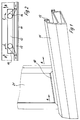
- FIG 1 the lower horizontal rail 11 is shown with the groove 13 open at the bottom.
- the sliding door leaf is identified by reference number 21.
- the lower bar bears the reference number 10.
- the sliding door leaf 21 can be moved in the direction of arrow A and counter to this direction.
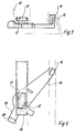
- Figure 2 shows that in each groove 12 of the respective spar 10 of the sliding door leaf 21 two arms 14 are locked, but rotatable. If the spar 10 of the sliding door leaf 1 is moved away from the groove 13 of the profile rail 11 in the direction of arrow B, the arms 14 rotate in opposite directions, as indicated by the two arrows C. The distance according to Figures 5 and 6 is then retained by the locking determination. Analogously, the two arms 14 act as a parallel guide.
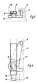
- the horizontal profile rail 11 and the horizontal bar 10 of the surrounding frame of a sliding door leaf 21 are shown in FIGS. 3 to 6.
- the profile rail 11 is provided with an open groove 13 and the horizontal spar 10 with an open groove 12.
- the groove 12 is T-shaped in cross section.
- the front end regions of an extension arm 14 engage in the grooves 12, 13. This is provided at the end associated with the T-groove 12 of the horizontal spar 10 with a pin which is transverse to its plane and to which a locking tab 15 is formed which, seen in the projection, is designed as a flat hexagon.
- the extension arm 14 carries on the same side an upstanding guide pin 16 which engages in the groove 13 of the profile rail.
- the locking tab 15 is clamped in a square opening of a flat insert 18, which is firmly in the T-groove 12 of the horizontal bar 10 is inserted so that the extension arm 14 does not move within the bar 10.
- FIG. 4 clearly shows that the extension arm 14 can be turned clockwise and then assumes the position shown in FIGS. 5 and 6. As a result, the distance between the profile rail 11 and the horizontal spar 10 is increased so that you can reach into the gap with your hand.
- FIG. 6 clearly shows that the opening movement is limited by the shape of the locking tab 15.
- a boom 19 is formed on the extension arm 14, which is provided with a locking cam 20 on the side facing the horizontal bar 10.
- the locking cam 20 of the arm 19 engages in the groove 12 of the horizontal spar 10.
- the free end of the locking cam 20 is semicircular, as shown in Figures 3 and 5. This makes it possible for the locking cam 20 to jump over the web facing away from the guide pin 16 and delimiting the groove 12 during the rotational movement of the deployment arm 14. It then lies on the outside of this web and prevents the sliding door leaf from automatically falling back into the sliding position.
- extension arm 14 For reasons of the simplified representation, only one extension arm 14 is shown in FIGS. 3 to 6. However, two extension arms 14 are provided for each sliding door leaf 21.
- the extension arm, not shown, is then mirror-inverted and inserted into the horizontal spar 10. This means that parallel guidance is achieved.
- the extension arm and the insert 18 are made of a suitable plastic.
Landscapes
- Health & Medical Sciences (AREA)
- Public Health (AREA)
- Epidemiology (AREA)
- General Health & Medical Sciences (AREA)
- Residential Or Office Buildings (AREA)
- Wing Frames And Configurations (AREA)
- Percussion Or Vibration Massage (AREA)
- Massaging Devices (AREA)
Abstract
Description
- Die vorliegende Erfindung bezieht sich auf eine Duschabtrennung mit einer Schiebetür, die aus Schiebetürflügeln gebildet ist, die jeweils einen Umfassungsrahmen aufweisen, deren oberer und unterer Holm in horizontalen Profilschienen verschiebbar geführt ist.
- Duschabtrennungen sind allgemein bekannt. Die den Einstieg in die Duschabtrennung ermöglichende Schiebetür besteht aus mehreren Schiebetürflügeln, die im zusammengeschobenen Zustand, mit Blick auf die Frontseite, hintereinander liegen und im auseinandergefahrenen Zustand den Einstieg verschließen. Die horizontalen Profilschienen und die die Umfassungsrahmen bildenden Holme sind üblicherweise Hohlprofile aus einer Aluminiumlegierung.
- Als kritischer Bereich sind die einander zugewandten Flächen der horizontalen Profilschiene und des Holmes des Umfassungsrahmens. Dieser Bereich ist praktisch unzugänglich und kann deshalb nicht gereinigt werden. Zu reinigen ist besonders der untere Bereich, da in den oberen Bereich normalerweise kein Wasser eindringt. Der vorliegenden Erfindung liegt die Aufgabe zugrunde, eine Duschabtrennung der eingangs genannten Art in konstruktiv einfacher Weise so auszubilden, daß der kritische Bereich zwischen der horizontalen Profilleiste und den Holmen der Umfassungsrahmen zwecks einer Reinigung gut zugänglich ist.
- Die gestellte Aufgabe wird gelöst, indem jedem Schiebetürflügel mindestens ein Ausstellarm zugeordnet ist, der mit einem Ende in eine Nut des Holmes des Umfassungsrahmens des jeweiligen Schiebetürflügels rastend jedoch drehbar festgelegt ist und mit dem anderen Ende in eine Nut der Profilschiene eingreift, so daß der zugeordnete Endbereich des Schiebetürflügels von der Schiebestellung in eine dazu parallele und abständige Reinigungsstellung auslenkbar ist.
- Der Ausstellarm ist aus einem elastisch verformbaren Material gefertigt, so daß er mit einem Ende zwar schließend in eine Nut des jeweiligen Holmes eingreifen kann jedoch beim Aufbringen einer Kraft drehbar ist. Ein solches Material ist beispielsweise Kunststoff, so daß die form- und materialfedernden Eigenschaften ausgenutzt werden können. In der normalen Schiebestellung der Schiebetürflügel liegen die einander zugewandten Flächen des horizontalen Holmes des Umfassungsrahmens und die Profilschiene aneinander oder sie stehen in einem ganz geringen Abstand zueinander. Wird durch Kraftaufbringung der untere Bereich eines jeden Schiebetürflügels von der Profilschiene weggedrückt, vergrößert sich der von dem Ausstellarm und der Profilschiene eingeschlossene Winkel. Da der Ausstellarm rastend jedoch drehbar in einer Nut des jeweiligen Holmes festgelegt ist, verbleibt jeder Schiebetürflügel in der abgedrückten Stellung, so daß die Reinigung erfolgen kann. Die Rückführung in die Schiebestellung erfolgt durch Andrücken an die Profilschiene.
- Zweckmäßigerweise sind jedem Schiebetürflügel zwei in den Endbereichen angeordnete Ausstellarme zugeordnet. Dadurch wird sinngemäß in funktioneller Hinsicht eine Parallelführung gebildet. In weiterer Ausgestaltung ist vorgesehen, daß an dem dem jeweiligen Holm zugeordneten Endbereich des Ausstellarmes ein Ausleger angeformt ist, der an seinem freien Ende einen Rastnocken aufweist, der in der Schiebestellung in eine Nut des Holmes rastend eingreift und der im Zuge des Überführens des jeweiligen Schiebetürflügels in die Reinigungsstellung einen die Nut begrenzenden Steg überspringt und außen an diesem anliegt. Dadurch ist in konstruktiv einfacher Weise sichergestellt, daß sowohl in der Schiebestellung als auch der Reinigungsstellung die Stellung des Schiebetürflügels fixiert ist, so daß es zu keinen ungewollten Bewegungen der Schiebetürflügel kommt. Die rastende und drehbare Festlegung des Ausstellarmes in einer Nut des Holmes ist besonders einfach, wenn in die Nut des Holmes ein flaches Einsatzstück fest eingesetzt ist, welches mit einer Durchbrechung versehen ist, in der eine Verriegelungslasche des Ausstellarmes festgeklemmt ist. Die Verriegelungslasche ist zweckmäßigerweise, in der Projektion mehreckig ausgebildet, beispielsweise in Form eines abgeflachten Sechseckes, so daß sie durch eine beispielsweise viereckige Durchbrechung des Einsatzstückes gesteckt werden kann und durch Verdrehung dann die Verbindung hergestellt wird.
- Weitere Kennzeichen und Merkmale einer vorteilhaften Ausgestaltung der vorliegenden Erfindung sind Gegenstand von weiteren Unteransprüchen und ergeben sich aus der nachfolgenden Beschreibung eines bevorzugten Ausführungsbeispiels.
- Es zeigen:
- Figur 1
- eine Teilansicht in perspektivischer Darstellung,
- Figur 2
- eine Schemaskizze als Draufsicht,
- Figur 3
- den in die Nuten der Profilschiene und des Holmes des Umfassungsrahmens eingreifenden Ausstellarm im Aufriß rein schematisch,
- Figur 4
- eine der Figur 1 entsprechende Draufsicht,
- Figur 5
- eine der Figur 1 entsprechende Darstellung, jedoch in der Reinigungsstellung,
- Figur 6
- eine der Figur 3 entsprechende Draufsicht.
- In der Figur 1 ist die untere horizontale Profilschiene 11 mit der nach unten offenen Nut 13 dargestellt. Der Schiebetürflügel ist durch das Bezugszeichen 21 gekennzeichnet. Der untere Holm trägt das Bezugszeichen 10. Der Schiebetürflügel 21 ist in Pfeilrichtung A und entgegen dieser Richtung verschiebbar. Die Figur 2 zeigt, daß in jeder Nut 12 des jeweiligen Holmes 10 des Schiebetürflügels 21 zwei Ausleger 14 rastend, jedoch drehbar, festgelegt sind. Wird der Holm 10 des Schiebetürflügels 1 von der Nut 13 der Profilschiene 11 in Pfeilrichtung B wegbewegt, drehen sich die Ausleger 14 in entgegengesetzten Richtungen, wie durch die beiden Pfeile C angedeutet ist. Der Abstand gemaß den Figuren 5 und 6 bleibt dann durch die rastende Festlegung erhalten. Sinngemäß wirken die beiden Ausleger 14 wie eine Parallelführung.
- Andeutungsweise ist in den Figuren 3 bis 6 die horizontale Profilschiene 11 und der horizontale Holm 10 des Umfassungsrahmens eines Schiebetürflügels 21 dargestellt. Die Profilschiene 11 ist mit einer offenen Nut 13 und der horizontale Holm 10 mit einer offenen Nut 12 versehen. Die Nut 12 ist im Querschnitt T-förmig ausgebildet. In die Nuten 12, 13 greifen die Stirnendbereiche eines Ausstellarmes 14 ein. Dieser ist an dem der T-Nut 12 des horizontalen Holmes 10 zugeordneten Ende mit einem quer zu seiner Ebene stehenden Zapfen versehen, an den eine Verriegelungslasche 15 angeformt ist, die, in der Projektion gesehen, als flaches Sechseck ausgebildet ist. Am gegenüberliegenden Ende trägt der Ausstellarm 14 an der gleichen Seite einen aufragenden Führungszapfen 16, der in die Nut 13 der Profilschiene eingreift. Die Verriegelungslasche 15 ist in einer viereckigen Durchbrechung eines flachen Einsatzstückes 18 festgeklemmt, welches fest in die T-Nut 12 des horizontalen Holmes 10 eingesetzt ist, damit sich der Ausstellarm 14 innerhalb des Holmes 10 nicht verschiebt. Die Figur 4 zeigt deutlich, daß der Ausstellarm 14 im Uhrzeigersinn gedreht werden kann und dann die in den Figuren 5 und 6 gezeigte Stellung einnimmt. Dadurch wird der Abstand zwischen der Profilschiene 11 und dem horizontalen Holm 10 so vergrößert, daß man mit der Hand in den Spalt hineinfassen kann. Die Figur 6 zeigt deutlich, daß durch die Form der Verriegelungslasche 15 die Ausstellbewegung begrenzt ist. An dem der Verriegelungslasche 15 zugeordneten Stirnende ist am Ausstellarm 14 ein Ausleger 19 angeformt, der an der dem horizontalen Holm 10 zugewandten Seite mit einem Rastnocken 20 versehen ist. In der Schiebestellung der Schiebetürflügel 21 greift der Rastnocken 20 des Auslegers 19 in die Nut 12 des horizontalen Holms 10 ein. Das freie Stirnende des Rastnockens 20 ist halbkreisförmig ausgebildet, wie die Figuren 3 und 5 zeigen. Dadurch ist es möglich, daß bei der Drehbewegung des Ausstellarmes 14 der Rastnocken 20 den dem Führungszapfen 16 abgewandten, die Nut 12 begrenzenden Steg überspringt. Er liegt dann außenseitig an diesem Steg an und verhindert, daß der Schiebetürflügel selbsttätig in die Schiebestellung zurückfällt.
- Aus Gründen der vereinfachten Darstellung ist in den Figuren 3 bis 6 nur ein Ausstellarm 14 dargestellt. Es sind jedoch für jeden Schiebetürflügel 21 zwei Ausstellarme 14 vorgesehen. Der nicht dargestellte Ausstellarm ist dann spiegelbildlich ausgebildet und in den horizontalen Holm 10 eingesetzt. Dadurch wird sinngemäß eine Parallelführung erreicht. Der Ausstellarm und das Einsatzstück 18 sind aus einem geeigneten Kunststoff gefertigt.
Claims (7)
- Duschabtrennung mit einer Schiebetür, die aus Schiebetürflügeln gebildet ist, die jeweils einen Umfassungsrahmen aufweisen, deren oberer und unterer Holm in horizontalen Profilschienen verschiebbar geführt sind, gekennzeichnet durch mindestens einen jedem Schiebetürflügel zugeordneten Ausstellarm (14), der mit einem Ende in eine Nut (12) des Holmes (10) des Umfassungsrahmens des jeweiligen Schiebetürflügels rastend jedoch drehbar festgelegt ist und mit dem anderen Ende in eine Nut (13) der Profilschiene (11) eingreift, so daß der zugeordnete Endbereich des Schiebetürflügels von der Schiebestellung in eine dazu parallele und abständige Reinigungsstellung auslenkbar ist.
- Duschabtrennung nach Anspruch 1, dadurch gekennzeichnet, daß jedem Schiebetürflügel zwei in den Endbereichen angeordnete Ausstellarme (14) zugeordnet sind.
- Duschabtrennung nach Anspruch 1, dadurch gekennzeichnet, daß an dem dem jeweiligen Holm (10) zugeordneten Endbereich des Ausstellarmes (14) ein Ausleger (19) angeformt ist, der an seinem freien Ende einen Rastnocken (20) aufweist, der in der Schiebestellung in die Nut (12) des Holmes (10) eingreift und der im Zuge des Überführens des jeweiligen Schiebetürflügels in die Reinigungsstellung einen die Nut (12) des Holmes (10) begrenzenden Steg überspringt und außen an diesen anliegt.
- Duschabtrennung nach Anspruch 1, dadurch gekennzeichnet, daß in die Nut (12) des Holmes (10) ein im Querschnitt flaches Einsatzstück (18) fest eingesetzt ist, welches mit einer Durchbrechung versehen ist, in der eine Verriegelungslasche (15) des Ausstellarmes festgeklemmt ist.
- Duschabtrennung nach Anspruch 1, dadurch gekennzeichnet, daß der Ausstellarm (14) an der dem Schiebetürflügel abgewandten Endbereich einen aufragenden Führungszapfen (16) aufweist, der in eine Nut (13) der Profilschiene (11) eingreift.
- Duschabtrennung nach einem oder mehreren der vorhergehenden Ansprüche, dadurch gekennzeichnet, daß die Durchbrechung (17) des Einsatzstückes (18) mehreckig, vorzugsweise viereckig ausgebildet ist und daß die eingreifende Verriegelungslasche (15) sechseckförmig mit ungleichen Kantenlängen ausgebildet ist.
- Duschabtrennung nach einem oder mehreren der vorhergehenden Ansprüche, dadurch gekennzeichnet, daß der Ausstellarm (14) und der Ausleger (19) als einstückiges Kunst stoffteil ausgebildet sind.
Applications Claiming Priority (2)
| Application Number | Priority Date | Filing Date | Title |
|---|---|---|---|
| DE9303156U DE9303156U1 (de) | 1993-03-04 | 1993-03-04 | Duschabtrennung |
| DE9303156U | 1993-03-04 |
Publications (2)
| Publication Number | Publication Date |
|---|---|
| EP0614643A1 true EP0614643A1 (de) | 1994-09-14 |
| EP0614643B1 EP0614643B1 (de) | 1996-10-09 |
Family
ID=6890171
Family Applications (1)
| Application Number | Title | Priority Date | Filing Date |
|---|---|---|---|
| EP94102953A Expired - Lifetime EP0614643B1 (de) | 1993-03-04 | 1994-02-28 | Duschabtrennung |
Country Status (3)
| Country | Link |
|---|---|
| EP (1) | EP0614643B1 (de) |
| AT (1) | ATE143785T1 (de) |
| DE (2) | DE9303156U1 (de) |
Cited By (1)
| Publication number | Priority date | Publication date | Assignee | Title |
|---|---|---|---|---|
| CN104314426A (zh) * | 2014-09-10 | 2015-01-28 | 平湖市欧文洁具有限公司 | 一种可防滑的单开式浴门 |
Families Citing this family (2)
| Publication number | Priority date | Publication date | Assignee | Title |
|---|---|---|---|---|
| DE102005003394B4 (de) * | 2005-01-24 | 2008-01-17 | KORALLE Sanitärprodukte GmbH | Führungssystem, insbesondere für Dusch- und Badewannenabtrennungen |
| AT517283B1 (de) | 2015-05-20 | 2018-10-15 | Tif Gmbh | Duschabtrennung mit Schiebetüre und Führungselement |
Citations (5)
| Publication number | Priority date | Publication date | Assignee | Title |
|---|---|---|---|---|
| GB2134167A (en) * | 1983-01-21 | 1984-08-08 | Guenter & Co Oni Metall | Shower cubicle sealing door |
| DE8618978U1 (de) * | 1986-07-15 | 1987-02-19 | Prader, Walter, Taufkirchen | Führungsschiene |
| EP0384215A1 (de) * | 1989-02-24 | 1990-08-29 | Koralle-Sanitärprodukte GmbH + Co. | Duschkabinen-Schiebetür IV |
| EP0439795A1 (de) * | 1990-01-30 | 1991-08-07 | Koralle-Sanitärprodukte GmbH + Co. | Duschabtrennung |
| DE4011849A1 (de) * | 1990-04-12 | 1991-10-17 | Hueppe Gmbh & Co | Untere fuehrung fuer eine schiebetrennwand, insbesondere fuer duschabtrennungen |
Family Cites Families (5)
| Publication number | Priority date | Publication date | Assignee | Title |
|---|---|---|---|---|
| DE2747480C2 (de) * | 1977-10-22 | 1979-08-30 | Heinz Georg Thun Baus (Schweiz) | Untere Führung für eine Schiebetrennwand |
| DE3540960C1 (en) * | 1985-11-19 | 1987-05-27 | Hueppe Gmbh | Shower partition with displaceable door elements |
| DE3722776A1 (de) * | 1987-07-09 | 1989-01-26 | Walter Prader | Untere fuehrung fuer eine trennwand fuer feuchtraeume |
| DE8900097U1 (de) * | 1988-12-28 | 1989-03-09 | Schulte-Duschkabinenbau GmbH & Co KG, 5768 Sundern | Duschabtrennung |
| DE4100252C1 (en) * | 1990-09-25 | 1991-11-21 | Altura Leiden Holding B.V., Maastricht, Nl | Partition for bath or shower - has door guide arm which engages bottom guide using slot |
-
1993
- 1993-03-04 DE DE9303156U patent/DE9303156U1/de not_active Expired - Lifetime
-
1994
- 1994-02-28 AT AT94102953T patent/ATE143785T1/de not_active IP Right Cessation
- 1994-02-28 EP EP94102953A patent/EP0614643B1/de not_active Expired - Lifetime
- 1994-02-28 DE DE59400784T patent/DE59400784D1/de not_active Expired - Fee Related
Patent Citations (5)
| Publication number | Priority date | Publication date | Assignee | Title |
|---|---|---|---|---|
| GB2134167A (en) * | 1983-01-21 | 1984-08-08 | Guenter & Co Oni Metall | Shower cubicle sealing door |
| DE8618978U1 (de) * | 1986-07-15 | 1987-02-19 | Prader, Walter, Taufkirchen | Führungsschiene |
| EP0384215A1 (de) * | 1989-02-24 | 1990-08-29 | Koralle-Sanitärprodukte GmbH + Co. | Duschkabinen-Schiebetür IV |
| EP0439795A1 (de) * | 1990-01-30 | 1991-08-07 | Koralle-Sanitärprodukte GmbH + Co. | Duschabtrennung |
| DE4011849A1 (de) * | 1990-04-12 | 1991-10-17 | Hueppe Gmbh & Co | Untere fuehrung fuer eine schiebetrennwand, insbesondere fuer duschabtrennungen |
Cited By (2)
| Publication number | Priority date | Publication date | Assignee | Title |
|---|---|---|---|---|
| CN104314426A (zh) * | 2014-09-10 | 2015-01-28 | 平湖市欧文洁具有限公司 | 一种可防滑的单开式浴门 |
| CN104314426B (zh) * | 2014-09-10 | 2016-01-20 | 平湖市欧文洁具有限公司 | 一种可防滑的单开式浴门 |
Also Published As
| Publication number | Publication date |
|---|---|
| DE59400784D1 (de) | 1996-11-14 |
| EP0614643B1 (de) | 1996-10-09 |
| ATE143785T1 (de) | 1996-10-15 |
| DE9303156U1 (de) | 1993-04-22 |
Similar Documents
| Publication | Publication Date | Title |
|---|---|---|
| DE2637974C2 (de) | Zusammenlegbarer Kindersitz für eine Einkaufskarre | |
| DE3637738C2 (de) | ||
| DE2461046A1 (de) | Frachtbehaelter | |
| DE2735787A1 (de) | Fuehrungselement fuer nachgiebig zu lagernde schiebetuerelemente sowie damit ausgeruestetes schiebetuerelement | |
| DE69806303T2 (de) | Rahmen mit Vorrichtung zur Unterstützung und Verbindung von Profilelementen und Gehausewänden | |
| EP0566983B1 (de) | Koffer | |
| EP0681081A1 (de) | Abschlusselement für Wandöffnungen in Gebäuden od. dgl. | |
| DE19603656A1 (de) | Verriegelbare Gleitlaufschiene für Fahrzeugsitze | |
| EP0614643B1 (de) | Duschabtrennung | |
| EP0016958B1 (de) | Rahmenprofil für ein Fenster, eine Tür od. dgl. | |
| DE19510941C2 (de) | Wandhalterung für einen Sanitärgegenstand | |
| EP0856626A2 (de) | Klemmbefestigungsvorrichtung für Beschlagteile | |
| DE69213144T2 (de) | Verschlusseinrichtung für eine umwendbare Tür, und Schrank mit solcher Einrichtung, für ein Elektrisches Gerät | |
| DE9114374U1 (de) | Treibstangenbeschlag für Fenster, Türen o.dgl. | |
| DE2029743A1 (de) | Metalleiter | |
| EP1193822A2 (de) | Sammelschienenträger | |
| DE3008556C2 (de) | Kippriegel- und Verschlußvorrichtung für Drehkippflügel-Fenster und -Türen oder dgl. | |
| DE3445234C2 (de) | ||
| DE9216213U1 (de) | Schließplatte | |
| DE4444413A1 (de) | Bausatz für Skelettkonstrukionen wie Regale, Rahmen, Ständer u. dgl. | |
| EP0338339A2 (de) | Sichtfenster für einen Schaltschrank oder einen Baugruppenträger | |
| DE9101068U1 (de) | Trennwand, insbesondere für Messe- und Ausstellungsstände | |
| DE19902400A1 (de) | Gebäudefenster oder Gebäudefenstertür sowie Blendrahmen für ein solches Fenster bzw. eine solche Fenstertür | |
| DE1630365C3 (de) | Öffnung fur Fenster, Türen od dgl an geschweißten Wagenkastengenppen, ins besondere von Großraumkraftwagen | |
| DE19723872A1 (de) | Zusammenbausystem für Duschkabinen |
Legal Events
| Date | Code | Title | Description |
|---|---|---|---|
| PUAI | Public reference made under article 153(3) epc to a published international application that has entered the european phase |
Free format text: ORIGINAL CODE: 0009012 |
|
| 17P | Request for examination filed |
Effective date: 19940719 |
|
| AK | Designated contracting states |
Kind code of ref document: A1 Designated state(s): AT CH DE FR GB LI |
|
| GRAG | Despatch of communication of intention to grant |
Free format text: ORIGINAL CODE: EPIDOS AGRA |
|
| 17Q | First examination report despatched |
Effective date: 19960212 |
|
| GRAH | Despatch of communication of intention to grant a patent |
Free format text: ORIGINAL CODE: EPIDOS IGRA |
|
| GRAH | Despatch of communication of intention to grant a patent |
Free format text: ORIGINAL CODE: EPIDOS IGRA |
|
| RBV | Designated contracting states (corrected) |
Designated state(s): AT CH DE FR GB LI |
|
| RAP1 | Party data changed (applicant data changed or rights of an application transferred) |
Owner name: KORALLE SANITAERPRODUKTE GMBH |
|
| GRAA | (expected) grant |
Free format text: ORIGINAL CODE: 0009210 |
|
| AK | Designated contracting states |
Kind code of ref document: B1 Designated state(s): AT CH DE FR GB LI |
|
| REF | Corresponds to: |
Ref document number: 143785 Country of ref document: AT Date of ref document: 19961015 Kind code of ref document: T |
|
| REG | Reference to a national code |
Ref country code: CH Ref legal event code: NV Representative=s name: ISLER & PEDRAZZINI AG |
|
| REF | Corresponds to: |
Ref document number: 59400784 Country of ref document: DE Date of ref document: 19961114 |
|
| GBT | Gb: translation of ep patent filed (gb section 77(6)(a)/1977) |
Effective date: 19961104 |
|
| ET | Fr: translation filed | ||
| PLBE | No opposition filed within time limit |
Free format text: ORIGINAL CODE: 0009261 |
|
| STAA | Information on the status of an ep patent application or granted ep patent |
Free format text: STATUS: NO OPPOSITION FILED WITHIN TIME LIMIT |
|
| 26N | No opposition filed | ||
| REG | Reference to a national code |
Ref country code: GB Ref legal event code: IF02 |
|
| PGFP | Annual fee paid to national office [announced via postgrant information from national office to epo] |
Ref country code: GB Payment date: 20040213 Year of fee payment: 11 |
|
| PGFP | Annual fee paid to national office [announced via postgrant information from national office to epo] |
Ref country code: FR Payment date: 20040218 Year of fee payment: 11 Ref country code: AT Payment date: 20040218 Year of fee payment: 11 |
|
| PG25 | Lapsed in a contracting state [announced via postgrant information from national office to epo] |
Ref country code: GB Free format text: LAPSE BECAUSE OF NON-PAYMENT OF DUE FEES Effective date: 20050228 Ref country code: AT Free format text: LAPSE BECAUSE OF NON-PAYMENT OF DUE FEES Effective date: 20050228 |
|
| GBPC | Gb: european patent ceased through non-payment of renewal fee |
Effective date: 20050228 |
|
| PG25 | Lapsed in a contracting state [announced via postgrant information from national office to epo] |
Ref country code: FR Free format text: LAPSE BECAUSE OF NON-PAYMENT OF DUE FEES Effective date: 20051031 |
|
| REG | Reference to a national code |
Ref country code: FR Ref legal event code: ST Effective date: 20051031 |
|
| REG | Reference to a national code |
Ref country code: CH Ref legal event code: PCAR Free format text: ISLER & PEDRAZZINI AG;POSTFACH 1772;8027 ZUERICH (CH) |
|
| PGFP | Annual fee paid to national office [announced via postgrant information from national office to epo] |
Ref country code: CH Payment date: 20080215 Year of fee payment: 15 |
|
| PGFP | Annual fee paid to national office [announced via postgrant information from national office to epo] |
Ref country code: DE Payment date: 20080130 Year of fee payment: 15 |
|
| REG | Reference to a national code |
Ref country code: CH Ref legal event code: PL |
|
| PG25 | Lapsed in a contracting state [announced via postgrant information from national office to epo] |
Ref country code: LI Free format text: LAPSE BECAUSE OF NON-PAYMENT OF DUE FEES Effective date: 20090228 Ref country code: CH Free format text: LAPSE BECAUSE OF NON-PAYMENT OF DUE FEES Effective date: 20090228 |
|
| PG25 | Lapsed in a contracting state [announced via postgrant information from national office to epo] |
Ref country code: DE Free format text: LAPSE BECAUSE OF NON-PAYMENT OF DUE FEES Effective date: 20090901 |