EP0614828A1 - Schiebeventil für Material in Pulverform oder in Form von kleinen Teilen - Google Patents
Schiebeventil für Material in Pulverform oder in Form von kleinen Teilen Download PDFInfo
- Publication number
- EP0614828A1 EP0614828A1 EP94200553A EP94200553A EP0614828A1 EP 0614828 A1 EP0614828 A1 EP 0614828A1 EP 94200553 A EP94200553 A EP 94200553A EP 94200553 A EP94200553 A EP 94200553A EP 0614828 A1 EP0614828 A1 EP 0614828A1
- Authority
- EP
- European Patent Office
- Prior art keywords
- valving member
- valve
- lip
- mouth
- wall
- Prior art date
- Legal status (The legal status is an assumption and is not a legal conclusion. Google has not performed a legal analysis and makes no representation as to the accuracy of the status listed.)
- Granted
Links
Images


Classifications
-
- B—PERFORMING OPERATIONS; TRANSPORTING
- B65—CONVEYING; PACKING; STORING; HANDLING THIN OR FILAMENTARY MATERIAL
- B65D—CONTAINERS FOR STORAGE OR TRANSPORT OF ARTICLES OR MATERIALS, e.g. BAGS, BARRELS, BOTTLES, BOXES, CANS, CARTONS, CRATES, DRUMS, JARS, TANKS, HOPPERS, FORWARDING CONTAINERS; ACCESSORIES, CLOSURES, OR FITTINGS THEREFOR; PACKAGING ELEMENTS; PACKAGES
- B65D90/00—Component parts, details or accessories for large containers
- B65D90/54—Gates or closures
- B65D90/58—Gates or closures having closure members sliding in the plane of the opening
- B65D90/587—Gates or closures having closure members sliding in the plane of the opening having a linear motion
-
- F—MECHANICAL ENGINEERING; LIGHTING; HEATING; WEAPONS; BLASTING
- F16—ENGINEERING ELEMENTS AND UNITS; GENERAL MEASURES FOR PRODUCING AND MAINTAINING EFFECTIVE FUNCTIONING OF MACHINES OR INSTALLATIONS; THERMAL INSULATION IN GENERAL
- F16K—VALVES; TAPS; COCKS; ACTUATING-FLOATS; DEVICES FOR VENTING OR AERATING
- F16K3/00—Gate valves or sliding valves, i.e. cut-off apparatus with closing members having a sliding movement along the seat for opening and closing
- F16K3/02—Gate valves or sliding valves, i.e. cut-off apparatus with closing members having a sliding movement along the seat for opening and closing with flat sealing faces; Packings therefor
- F16K3/0227—Packings
-
- F—MECHANICAL ENGINEERING; LIGHTING; HEATING; WEAPONS; BLASTING
- F16—ENGINEERING ELEMENTS AND UNITS; GENERAL MEASURES FOR PRODUCING AND MAINTAINING EFFECTIVE FUNCTIONING OF MACHINES OR INSTALLATIONS; THERMAL INSULATION IN GENERAL
- F16K—VALVES; TAPS; COCKS; ACTUATING-FLOATS; DEVICES FOR VENTING OR AERATING
- F16K3/00—Gate valves or sliding valves, i.e. cut-off apparatus with closing members having a sliding movement along the seat for opening and closing
- F16K3/02—Gate valves or sliding valves, i.e. cut-off apparatus with closing members having a sliding movement along the seat for opening and closing with flat sealing faces; Packings therefor
- F16K3/0281—Guillotine or blade-type valves, e.g. no passage through the valve member
-
- F—MECHANICAL ENGINEERING; LIGHTING; HEATING; WEAPONS; BLASTING
- F16—ENGINEERING ELEMENTS AND UNITS; GENERAL MEASURES FOR PRODUCING AND MAINTAINING EFFECTIVE FUNCTIONING OF MACHINES OR INSTALLATIONS; THERMAL INSULATION IN GENERAL
- F16K—VALVES; TAPS; COCKS; ACTUATING-FLOATS; DEVICES FOR VENTING OR AERATING
- F16K3/00—Gate valves or sliding valves, i.e. cut-off apparatus with closing members having a sliding movement along the seat for opening and closing
- F16K3/30—Details
- F16K3/316—Guiding of the slide
- F16K3/3165—Guiding of the slide with rollers or balls
Definitions
- This invention relates to a slide valve for material in powder or small-piece form, comprising a rigid frame with walls defining a passage mouth for the material and a valving member in the form of a horizontal flat plate movable horizontally through a slot provided in a said wall and having a width such as to close the passage mouth.
- valves A typical application of such valves is on the lower surface of silos or below a hopper for intercepting the descent of the material.
- valves A technical problem connected with such valves is to prevent the material seeping beyond the valving member when this is in its closure position and to also prevent the material seeping through the passage slot for the valving member when this is at rest and and is then pulled rearwards.
- This derives from the fact that said valves are generally of relatively very large dimensions (the mouth usually has dimensions exceeding 15 cm x 15 cm) and therefore require robust components formed by structural steel working, their parts in addition generally operating in the presence of material which can be very abrasive.
- An object of the present invention is therefore solve said technical problems within the framework of an operationally reliable solution which is constructionally simple and economical.
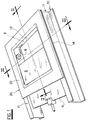
- Figure 1 is a perspective view of the valve.
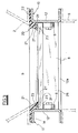
- Figure 2 is a section on the vertical plane II-II of Figure 1.
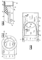
- Figure 3 is a section on the vertical plane III-III of Figure 1.
- Figure 4 is a plan view of an embodiment of the valve different from the preceding of Figure 1.
- Figure 5 is a plan view of a further embodiment of the valve different from the preceding.
- Figure 6 is a section on the plane VI-VI of Figure 5.
- Figure 7 is a sectional view similar to Figure 2, showing a further embodiment of the invention.
- the valve shown in Figures 1-3 comprises a rigid frame 10, in particular of metal, comprising four section bars of C cross-section arranged to define a square or rectangle. Each of the section bars 11 comprises a vertical wall 12. The four vertical walls 12 define a prismatic mouth 8 for passage of the material.
- One of the walls 12, indicated by 12a, possesses a horizontally extending slot 13 through which a valving member 9 in the form of a horizontal flat plate passes with horizontal movement.
- the valving member 9 is of such a size as to close the passage mouth 8 when viewed in plan. Specifically, the width of the valving member 9 is equal, save for a small clearance, to the distance between the two opposing walls 12 along which it slides, whereas the length of the valving member 9 is greater than the distance between the other two walls 12 so that, even when in its closure position, the valving member 9 projects beyond the mouth 8 through the slot 13.
- the mouth 8 is closed by pushing the valving member 9 forwards into the mouth 8, opening being achieved vice versa by pulling the valving member 9 rearwards.
- the valving member 9 is guided by idle wheels 6 pivoted to two lateral walls 12 to act against the lower surface of the valving member.
- the frame 10 is fixed between an upper convergent surface 2 (for example a hopper or the lower surface of a silo) and a lower transit surface 3 for the material.
- the material hence descends from the top downwards through the mouth 8 ( Figures 2 and 3).
- a gasket means 20 of elastomeric material is fixed to the frame 10 to extend in the form of a closed ring along the upper peripheral edge of the mouth 8.
- the gasket means 20 consequently comprises four sides extending along the four upper sides of the mouth 8.
- the gasket means 20 When viewed in vertical cross-section ( Figures 2 and 3), the gasket means 20 comprises a lip 21 which projects downwards towards the interior of the mouth 8.
- Said lip 21 extends along the four sides of the upper peripheral edge of the mouth 8, with its outer surface converging downwards.
- the lower surface of said lip 21 is in contact with the upper surface of the valving member 9 when this is inserted into the mouth 8.
- the gasket means 20 also comprises a horizontal flat rim 22 which is fixed to a corresponding upper horizontal rim 14 of the frame 10, the rim 14 being formed by the upper horizontal flanges of the section bars 11.
- the lip 21 is joined to the inner edge of the flat rim 22.
- the gasket means 20 also comprises, on that wall 12 opposite the wall 12a comprising the slot 13, a substantially vertical appendix 24 which adheres to said wall 12 and projects downwards below the lip 21 so that the front edge 9' of the valving member 9 abuts against said appendix 24 to increase the anti-seepage action.
- the lip 21 can comprise one or more longitudinal recesses 23 (ie extending parallel to the longitudinal extension of the sides of the mouth 8), to define one or more longitudinal ridges 21' to increase the sealing action of the lip 21 against the valving member.
- said recesses 23 are provided along three sides of the mouth 8 but not in that part of the lip positioned along that wall 12 opposite the wall 12a.
- the lip 21 projects downwards slightly beyond the ideal plane in which the upper surface of the valving member 9 moves. Consequently, when the valving member 9 is inserted into the mouth 8 into contact with the lip 21, this is urged upwards and by reaction presses against the valving member 9 with a certain preload.
- a rectilinear gasket 26 is also provided, fixed to the wall 12a below the valving member 9 and extending along the slot 13.
- the gasket 26 has an upper lip in contact with the upper surface of the valving member 9.
- the gasket 26 is also arranged to scrape the lower surface of the valving member 9 when this is pulled rearwards from the mouth 8. Consequently by virtue of the combination of the gasket 26 and the gasket means 20, any seepage through the slot 13 is prevented, both when the valving member 9 is at rest in its opening or closure position, and while it is being pulled rearwards.
- the upper surface of the valving member 9 can be of elastomeric material, said elastomer having a greater hardness than the elastomer of the gasket means 20. In this manner a surface can be obtained having excellent abrasion resistance while being sufficiently slidable when in contact with the lip 21.
- the gasket means 20 can be formed by moulding the elastomeric material in the fluid state onto the frame 10. Both good adhesion to the frame 10 and high constructional accuracy are achieved.
- valve of the invention has been described and claimed with reference to the most usual spatial arrangement, ie that in which the valving member 9 lies horizontally and the material to be intercepted lies above the valve.
- the valve can however be of a different spatial arrangement, for example it can be variously rotated from the illustrated position.
- the mouth 8 has a usual circular shape and the valving member 9 has a known rectangular plan shape with its front portion in the form of a semicircle.
- the embodiment shown in Figure 5 is new in that the mouth 8 has a convex arched side 8a opposite the side comprising the passage slot.
- the front side of the valving member 9 is of concave arched shape.
- This embodiment facilitates the descent of the material, particularly when the valve is close to closure, by preventing "bridges” and other obstructions which easily occur when the material passes through a long narrow slot.
- Figure 6 is a section showing the shape assumed in this type of valve by the gasket means 20 according to the invention, positioned on the side 8a.
- the frame 10 lies in a substantially horizontal plane, whereas the valving member 9 slides in a plane inclined to the horizontal, the inclination being directed downwards towards that wall 12 opposite the wall 12a (comprising the slot 13).
- the lip 21 has its upper surface 21' inclined downwards towards the centre of the passage mouth 8.
- the inclination of the valving member 9 together with that of the surface 21' facilitate descent of the material when the valving member is semi-closed, and in particular when close to closure.
- This embodiment can be applied to any of the valve types shown in Figures 1, 4 and 5.
Landscapes
- Engineering & Computer Science (AREA)
- General Engineering & Computer Science (AREA)
- Mechanical Engineering (AREA)
- Powder Metallurgy (AREA)
- Multiple-Way Valves (AREA)
- Lift Valve (AREA)
- Sliding Valves (AREA)
- Centrifugal Separators (AREA)
- Injection Moulding Of Plastics Or The Like (AREA)
Applications Claiming Priority (2)
| Application Number | Priority Date | Filing Date | Title |
|---|---|---|---|
| IT93RE000015U IT230975Y1 (it) | 1993-03-08 | 1993-03-08 | Valvola a ghigliottina per materiale in polvere o in piccola pezzatura. |
| ITRE930015U | 1993-03-08 |
Publications (3)
| Publication Number | Publication Date |
|---|---|
| EP0614828A1 true EP0614828A1 (de) | 1994-09-14 |
| EP0614828B1 EP0614828B1 (de) | 1998-06-17 |
| EP0614828B2 EP0614828B2 (de) | 2002-05-02 |
Family
ID=11398342
Family Applications (1)
| Application Number | Title | Priority Date | Filing Date |
|---|---|---|---|
| EP94200553A Expired - Lifetime EP0614828B2 (de) | 1993-03-08 | 1994-03-04 | Schiebeventil für Material in Pulverform oder in Form von kleinen Teilen |
Country Status (4)
| Country | Link |
|---|---|
| EP (1) | EP0614828B2 (de) |
| AT (1) | ATE167447T1 (de) |
| DE (1) | DE69411050T3 (de) |
| IT (1) | IT230975Y1 (de) |
Cited By (4)
| Publication number | Priority date | Publication date | Assignee | Title |
|---|---|---|---|---|
| EP2067529A1 (de) * | 2007-12-06 | 2009-06-10 | Mettler-Toledo AG | Umfüllvorrichtung für Laborbehälter |
| US20160236861A1 (en) * | 2013-10-02 | 2016-08-18 | Wamgroup S.P.A. | Slide valve for a hopper containing powdered material or material with a small grain size |
| US20170167621A1 (en) * | 2014-02-07 | 2017-06-15 | Process Components Limited | Slide valve |
| WO2022056602A1 (en) * | 2020-09-21 | 2022-03-24 | Schenck Process Australia Pty Limited | Isolation gate valve |
Families Citing this family (1)
| Publication number | Priority date | Publication date | Assignee | Title |
|---|---|---|---|---|
| DE102024127698A1 (de) * | 2024-09-25 | 2026-03-26 | Khd Humboldt Wedag Gmbh | Absperrschieber für eine Hochdruckwalzenpresse |
Citations (5)
| Publication number | Priority date | Publication date | Assignee | Title |
|---|---|---|---|---|
| FR1317186A (fr) * | 1962-03-12 | 1963-02-01 | Shell Int Research | Vanne à tiroir |
| GB2071813A (en) * | 1980-03-14 | 1981-09-23 | Peart E & Co Ltd | Seal and gate valve incorporating same |
| EP0092008A1 (de) * | 1982-04-14 | 1983-10-26 | Fabricated Metals, Inc. | Behälter mit Schmetterlingsklappe |
| FR2640598A1 (fr) * | 1988-12-16 | 1990-06-22 | Constantin Pierre | Dispositif obturateur d'orifices de transfert de produit, notamment d'un conteneur a un autre |
| US5046432A (en) * | 1989-04-28 | 1991-09-10 | Degelman Industries Limited | Unloading gate for bulk material handling containers |
Family Cites Families (2)
| Publication number | Priority date | Publication date | Assignee | Title |
|---|---|---|---|---|
| DE2431649C2 (de) † | 1974-07-02 | 1983-09-01 | Carl Still Gmbh & Co Kg, 4350 Recklinghausen | Gasdichter Schieber für Schüttgüter |
| DE2902430C2 (de) † | 1979-01-23 | 1984-07-26 | Rohrleitungs- u. Apparatebau D. Richter GmbH & Co, 5090 Leverkusen | Schieber-Verschlußvorrichtung für die Auslaßöffnung eines Behälters für Schüttgut mit einer Schieberplatte |
-
1993
- 1993-03-08 IT IT93RE000015U patent/IT230975Y1/it active IP Right Grant
-
1994
- 1994-03-04 EP EP94200553A patent/EP0614828B2/de not_active Expired - Lifetime
- 1994-03-04 DE DE69411050T patent/DE69411050T3/de not_active Expired - Lifetime
- 1994-03-04 AT AT94200553T patent/ATE167447T1/de not_active IP Right Cessation
Patent Citations (5)
| Publication number | Priority date | Publication date | Assignee | Title |
|---|---|---|---|---|
| FR1317186A (fr) * | 1962-03-12 | 1963-02-01 | Shell Int Research | Vanne à tiroir |
| GB2071813A (en) * | 1980-03-14 | 1981-09-23 | Peart E & Co Ltd | Seal and gate valve incorporating same |
| EP0092008A1 (de) * | 1982-04-14 | 1983-10-26 | Fabricated Metals, Inc. | Behälter mit Schmetterlingsklappe |
| FR2640598A1 (fr) * | 1988-12-16 | 1990-06-22 | Constantin Pierre | Dispositif obturateur d'orifices de transfert de produit, notamment d'un conteneur a un autre |
| US5046432A (en) * | 1989-04-28 | 1991-09-10 | Degelman Industries Limited | Unloading gate for bulk material handling containers |
Cited By (7)
| Publication number | Priority date | Publication date | Assignee | Title |
|---|---|---|---|---|
| EP2067529A1 (de) * | 2007-12-06 | 2009-06-10 | Mettler-Toledo AG | Umfüllvorrichtung für Laborbehälter |
| US7818946B2 (en) | 2007-12-06 | 2010-10-26 | Mettler-Toledo Ag | Transfer device for laboratory containers |
| US20160236861A1 (en) * | 2013-10-02 | 2016-08-18 | Wamgroup S.P.A. | Slide valve for a hopper containing powdered material or material with a small grain size |
| US9809382B2 (en) * | 2013-10-02 | 2017-11-07 | Wamgroup S.P.A. | Slide valve for a hopper containing powdered material or material with a small grain size |
| US20170167621A1 (en) * | 2014-02-07 | 2017-06-15 | Process Components Limited | Slide valve |
| WO2022056602A1 (en) * | 2020-09-21 | 2022-03-24 | Schenck Process Australia Pty Limited | Isolation gate valve |
| US12173808B2 (en) | 2020-09-21 | 2024-12-24 | Schenck Process Australia Pty Limited | Isolation gate valve |
Also Published As
| Publication number | Publication date |
|---|---|
| EP0614828B1 (de) | 1998-06-17 |
| ITRE930015V0 (it) | 1993-03-08 |
| DE69411050T2 (de) | 1999-01-28 |
| ATE167447T1 (de) | 1998-07-15 |
| EP0614828B2 (de) | 2002-05-02 |
| IT230975Y1 (it) | 1999-07-05 |
| DE69411050D1 (de) | 1998-07-23 |
| ITRE930015U1 (it) | 1994-09-08 |
| DE69411050T3 (de) | 2002-11-07 |
Similar Documents
| Publication | Publication Date | Title |
|---|---|---|
| US7487616B2 (en) | Rail car door sealing gasket | |
| US4785966A (en) | Slide gate assembly | |
| CA2357591A1 (en) | Fastener closure arrangement for flexible packages | |
| EP0614828A1 (de) | Schiebeventil für Material in Pulverform oder in Form von kleinen Teilen | |
| US20070164248A1 (en) | Valves | |
| CA2560666A1 (en) | Knife gate valve having elastomeric seals | |
| CN105764815B (zh) | 用于粉末状物料或小颗粒尺寸物料的滑阀 | |
| US4491253A (en) | Container with butterfly valve | |
| GB1344906A (en) | Closure assembly | |
| US4528913A (en) | Gravity outlet sliding gate seal | |
| US5553913A (en) | Motor vehicle sliding roof panel seal | |
| US3884390A (en) | Push-pull closure with probe to prevent clogging | |
| US2914000A (en) | Bottom-discharging hopper closure assembly | |
| JPS59435B2 (ja) | 排出スライドゲ−ト装置 | |
| EP0047273A1 (de) | Dichtungsmittel, zunächst für eine schütze oder ein schleusentor | |
| ATE150147T1 (de) | Schieberarmatur mit dichtung | |
| US4549497A (en) | Device for underwater sealing ports or similar, notably the bottom traps from hopper barges | |
| IE914570A1 (en) | Spherical valve | |
| EP1505007A1 (de) | Verschlussvorrichtung für fliessfähiges Material aufnehmende Behälter und Behälter mit derselben | |
| JPH031665Y2 (de) | ||
| EP0101272A3 (de) | Kippventil für zähe Fluide für Druckbehälter | |
| JP2548235Y2 (ja) | バケットエレベータの可動底板シール装置 | |
| PL1848906T3 (pl) | Zawór odcinający | |
| US20090007985A1 (en) | Apparatus for Transferring Bulk Material | |
| TW367299B (en) | Device for the discontinuous dosed application of granular material from a storage container |
Legal Events
| Date | Code | Title | Description |
|---|---|---|---|
| PUAI | Public reference made under article 153(3) epc to a published international application that has entered the european phase |
Free format text: ORIGINAL CODE: 0009012 |
|
| AK | Designated contracting states |
Kind code of ref document: A1 Designated state(s): AT BE CH DE DK ES FR GB IT LI NL SE |
|
| 17P | Request for examination filed |
Effective date: 19950214 |
|
| 17Q | First examination report despatched |
Effective date: 19960228 |
|
| GRAG | Despatch of communication of intention to grant |
Free format text: ORIGINAL CODE: EPIDOS AGRA |
|
| GRAG | Despatch of communication of intention to grant |
Free format text: ORIGINAL CODE: EPIDOS AGRA |
|
| GRAH | Despatch of communication of intention to grant a patent |
Free format text: ORIGINAL CODE: EPIDOS IGRA |
|
| GRAH | Despatch of communication of intention to grant a patent |
Free format text: ORIGINAL CODE: EPIDOS IGRA |
|
| GRAA | (expected) grant |
Free format text: ORIGINAL CODE: 0009210 |
|
| AK | Designated contracting states |
Kind code of ref document: B1 Designated state(s): AT BE CH DE DK ES FR GB IT LI NL SE |
|
| PG25 | Lapsed in a contracting state [announced via postgrant information from national office to epo] |
Ref country code: NL Free format text: LAPSE BECAUSE OF FAILURE TO SUBMIT A TRANSLATION OF THE DESCRIPTION OR TO PAY THE FEE WITHIN THE PRESCRIBED TIME-LIMIT Effective date: 19980617 Ref country code: LI Free format text: LAPSE BECAUSE OF FAILURE TO SUBMIT A TRANSLATION OF THE DESCRIPTION OR TO PAY THE FEE WITHIN THE PRESCRIBED TIME-LIMIT Effective date: 19980617 Ref country code: ES Free format text: THE PATENT HAS BEEN ANNULLED BY A DECISION OF A NATIONAL AUTHORITY Effective date: 19980617 Ref country code: CH Free format text: LAPSE BECAUSE OF FAILURE TO SUBMIT A TRANSLATION OF THE DESCRIPTION OR TO PAY THE FEE WITHIN THE PRESCRIBED TIME-LIMIT Effective date: 19980617 Ref country code: BE Free format text: LAPSE BECAUSE OF FAILURE TO SUBMIT A TRANSLATION OF THE DESCRIPTION OR TO PAY THE FEE WITHIN THE PRESCRIBED TIME-LIMIT Effective date: 19980617 Ref country code: AT Free format text: LAPSE BECAUSE OF FAILURE TO SUBMIT A TRANSLATION OF THE DESCRIPTION OR TO PAY THE FEE WITHIN THE PRESCRIBED TIME-LIMIT Effective date: 19980617 |
|
| REF | Corresponds to: |
Ref document number: 167447 Country of ref document: AT Date of ref document: 19980715 Kind code of ref document: T |
|
| REG | Reference to a national code |
Ref country code: CH Ref legal event code: EP |
|
| ITF | It: translation for a ep patent filed | ||
| REF | Corresponds to: |
Ref document number: 69411050 Country of ref document: DE Date of ref document: 19980723 |
|
| PG25 | Lapsed in a contracting state [announced via postgrant information from national office to epo] |
Ref country code: SE Free format text: LAPSE BECAUSE OF FAILURE TO SUBMIT A TRANSLATION OF THE DESCRIPTION OR TO PAY THE FEE WITHIN THE PRESCRIBED TIME-LIMIT Effective date: 19980917 Ref country code: DK Free format text: LAPSE BECAUSE OF FAILURE TO SUBMIT A TRANSLATION OF THE DESCRIPTION OR TO PAY THE FEE WITHIN THE PRESCRIBED TIME-LIMIT Effective date: 19980917 |
|
| ET | Fr: translation filed | ||
| NLV1 | Nl: lapsed or annulled due to failure to fulfill the requirements of art. 29p and 29m of the patents act | ||
| REG | Reference to a national code |
Ref country code: CH Ref legal event code: PL |
|
| PLBI | Opposition filed |
Free format text: ORIGINAL CODE: 0009260 |
|
| 26 | Opposition filed |
Opponent name: WAESCHLE GMBH Effective date: 19990218 |
|
| PLBF | Reply of patent proprietor to notice(s) of opposition |
Free format text: ORIGINAL CODE: EPIDOS OBSO |
|
| PLBF | Reply of patent proprietor to notice(s) of opposition |
Free format text: ORIGINAL CODE: EPIDOS OBSO |
|
| PLAW | Interlocutory decision in opposition |
Free format text: ORIGINAL CODE: EPIDOS IDOP |
|
| APAC | Appeal dossier modified |
Free format text: ORIGINAL CODE: EPIDOS NOAPO |
|
| APAE | Appeal reference modified |
Free format text: ORIGINAL CODE: EPIDOS REFNO |
|
| PLBQ | Unpublished change to opponent data |
Free format text: ORIGINAL CODE: EPIDOS OPPO |
|
| PLAB | Opposition data, opponent's data or that of the opponent's representative modified |
Free format text: ORIGINAL CODE: 0009299OPPO |
|
| PLBI | Opposition filed |
Free format text: ORIGINAL CODE: 0009260 |
|
| 26 | Opposition filed |
Opponent name: WAESCHLE GMBH & CO. KG Effective date: 19990218 |
|
| APAC | Appeal dossier modified |
Free format text: ORIGINAL CODE: EPIDOS NOAPO |
|
| APAE | Appeal reference modified |
Free format text: ORIGINAL CODE: EPIDOS REFNO |
|
| APAC | Appeal dossier modified |
Free format text: ORIGINAL CODE: EPIDOS NOAPO |
|
| PLAW | Interlocutory decision in opposition |
Free format text: ORIGINAL CODE: EPIDOS IDOP |
|
| REG | Reference to a national code |
Ref country code: GB Ref legal event code: IF02 |
|
| PUAH | Patent maintained in amended form |
Free format text: ORIGINAL CODE: 0009272 |
|
| STAA | Information on the status of an ep patent application or granted ep patent |
Free format text: STATUS: PATENT MAINTAINED AS AMENDED |
|
| 27A | Patent maintained in amended form |
Effective date: 20020502 |
|
| AK | Designated contracting states |
Kind code of ref document: B2 Designated state(s): AT BE CH DE DK ES FR GB IT LI NL SE |
|
| ET3 | Fr: translation filed ** decision concerning opposition | ||
| APAH | Appeal reference modified |
Free format text: ORIGINAL CODE: EPIDOSCREFNO |
|
| PGFP | Annual fee paid to national office [announced via postgrant information from national office to epo] |
Ref country code: IT Payment date: 20120327 Year of fee payment: 19 |
|
| PGFP | Annual fee paid to national office [announced via postgrant information from national office to epo] |
Ref country code: GB Payment date: 20130328 Year of fee payment: 20 |
|
| PGFP | Annual fee paid to national office [announced via postgrant information from national office to epo] |
Ref country code: DE Payment date: 20130531 Year of fee payment: 20 |
|
| PGFP | Annual fee paid to national office [announced via postgrant information from national office to epo] |
Ref country code: FR Payment date: 20130422 Year of fee payment: 20 |
|
| REG | Reference to a national code |
Ref country code: DE Ref legal event code: R071 Ref document number: 69411050 Country of ref document: DE |
|
| REG | Reference to a national code |
Ref country code: GB Ref legal event code: PE20 Expiry date: 20140303 |
|
| PG25 | Lapsed in a contracting state [announced via postgrant information from national office to epo] |
Ref country code: GB Free format text: LAPSE BECAUSE OF EXPIRATION OF PROTECTION Effective date: 20140303 Ref country code: DE Free format text: LAPSE BECAUSE OF EXPIRATION OF PROTECTION Effective date: 20140305 |