EP0614831A1 - Kettenförderer - Google Patents
Kettenförderer Download PDFInfo
- Publication number
- EP0614831A1 EP0614831A1 EP94102880A EP94102880A EP0614831A1 EP 0614831 A1 EP0614831 A1 EP 0614831A1 EP 94102880 A EP94102880 A EP 94102880A EP 94102880 A EP94102880 A EP 94102880A EP 0614831 A1 EP0614831 A1 EP 0614831A1
- Authority
- EP
- European Patent Office
- Prior art keywords
- belt
- chains
- chain
- drive
- bars
- Prior art date
- Legal status (The legal status is an assumption and is not a legal conclusion. Google has not performed a legal analysis and makes no representation as to the accuracy of the status listed.)
- Granted
Links
- 125000006850 spacer group Chemical group 0.000 claims description 9
- 230000000452 restraining effect Effects 0.000 claims description 2
- 230000000630 rising effect Effects 0.000 claims 1
- 238000003466 welding Methods 0.000 description 4
- 239000000314 lubricant Substances 0.000 description 3
- 230000000712 assembly Effects 0.000 description 2
- 238000000429 assembly Methods 0.000 description 2
- 235000016936 Dendrocalamus strictus Nutrition 0.000 description 1
- 230000005540 biological transmission Effects 0.000 description 1
- 230000015572 biosynthetic process Effects 0.000 description 1
- 239000000872 buffer Substances 0.000 description 1
- 230000007547 defect Effects 0.000 description 1
- 235000013305 food Nutrition 0.000 description 1
- 230000001788 irregular Effects 0.000 description 1
- 230000000284 resting effect Effects 0.000 description 1
- 238000010257 thawing Methods 0.000 description 1
Images


Classifications
-
- B—PERFORMING OPERATIONS; TRANSPORTING
- B65—CONVEYING; PACKING; STORING; HANDLING THIN OR FILAMENTARY MATERIAL
- B65G—TRANSPORT OR STORAGE DEVICES, e.g. CONVEYORS FOR LOADING OR TIPPING, SHOP CONVEYOR SYSTEMS OR PNEUMATIC TUBE CONVEYORS
- B65G17/00—Conveyors having an endless traction element, e.g. a chain, transmitting movement to a continuous or substantially-continuous load-carrying surface or to a series of individual load-carriers; Endless-chain conveyors in which the chains form the load-carrying surface
- B65G17/06—Conveyors having an endless traction element, e.g. a chain, transmitting movement to a continuous or substantially-continuous load-carrying surface or to a series of individual load-carriers; Endless-chain conveyors in which the chains form the load-carrying surface having a load-carrying surface formed by a series of interconnected, e.g. longitudinal, links, plates, or platforms
- B65G17/063—Conveyors having an endless traction element, e.g. a chain, transmitting movement to a continuous or substantially-continuous load-carrying surface or to a series of individual load-carriers; Endless-chain conveyors in which the chains form the load-carrying surface having a load-carrying surface formed by a series of interconnected, e.g. longitudinal, links, plates, or platforms the load carrying surface being formed by profiles, rods, bars, rollers or the like attached to more than one traction element
-
- B—PERFORMING OPERATIONS; TRANSPORTING
- B65—CONVEYING; PACKING; STORING; HANDLING THIN OR FILAMENTARY MATERIAL
- B65G—TRANSPORT OR STORAGE DEVICES, e.g. CONVEYORS FOR LOADING OR TIPPING, SHOP CONVEYOR SYSTEMS OR PNEUMATIC TUBE CONVEYORS
- B65G21/00—Supporting or protective framework or housings for endless load-carriers or traction elements of belt or chain conveyors
- B65G21/16—Supporting or protective framework or housings for endless load-carriers or traction elements of belt or chain conveyors for conveyors having endless load-carriers movable in curved paths
- B65G21/18—Supporting or protective framework or housings for endless load-carriers or traction elements of belt or chain conveyors for conveyors having endless load-carriers movable in curved paths in three-dimensionally curved paths
-
- B—PERFORMING OPERATIONS; TRANSPORTING
- B65—CONVEYING; PACKING; STORING; HANDLING THIN OR FILAMENTARY MATERIAL
- B65G—TRANSPORT OR STORAGE DEVICES, e.g. CONVEYORS FOR LOADING OR TIPPING, SHOP CONVEYOR SYSTEMS OR PNEUMATIC TUBE CONVEYORS
- B65G2201/00—Indexing codes relating to handling devices, e.g. conveyors, characterised by the type of product or load being conveyed or handled
- B65G2201/02—Articles
-
- B—PERFORMING OPERATIONS; TRANSPORTING
- B65—CONVEYING; PACKING; STORING; HANDLING THIN OR FILAMENTARY MATERIAL
- B65G—TRANSPORT OR STORAGE DEVICES, e.g. CONVEYORS FOR LOADING OR TIPPING, SHOP CONVEYOR SYSTEMS OR PNEUMATIC TUBE CONVEYORS
- B65G2207/00—Indexing codes relating to constructional details, configuration and additional features of a handling device, e.g. Conveyors
- B65G2207/24—Helical or spiral conveying path
Definitions
- the present invention relates to a chain conveyor of the type comprising an endless conveyor belt sliding along guide means which develop along a predetermined path, wherein the conveyor belt comprises a first and a second drive chain formed by annular elements.
- the annular elements of one chain are connected to corresponding annular elements of the other chain by means of cross bars defining the surface of the conveyor belt.
- Drive means are also provided, comprising at least one drive wheel which drives a chain of the belt.
- Chain conveyors of the abovementioned type, are widely used in a number of areas due to their intrinsic features which allow them to support heavy loads and to operate in different environments.
- the whole conveyor belt is supported and guided by means of the same drive chains which slide along guide channels which surround part of the profile of the chain itself. Consequently chain conveyors of this type have a number of disadvantages due to their structure and the consequent manner of supporting and guiding the conveyor belt.
- belt guide and slide elements in the form of a channel, or such as to surround substantially most of the profile of the rings of the chains, causes considerable dragging friction, not only due to the large surface of contact with the chains, but also to the additional friction caused by structural and assembly defects of the various parts which make up the system.
- the inevitable irregularities of shape and size of the rings may cause greater friction against the guide surfaces and consequently require the use of more powerful drive assemblies, particularly for conveyors which develop along paths of considerable length or with extremely complex or spiral paths.
- a further disadvantage consists in the excessive weight of the conveyor belt, due to the fact that the chains had to be dimensioned to resist the high drive stresses and due to the need to use cross bars with a considerable section in order to prevent their deformation and that of the conveyor belt itself on account of the long support distance of the bars, particularly in belts of greater width. Moreover, bars of greater section create once again greater weight for the belt to drive.
- a lubricating agent is poured into said channels.
- Said lubricant contaminates in many cases the product conveyed by the belt, also due to the fact that the conveying surface of the belt is formed by bars welded directly onto the rings of the chain, particularly if these bars are attached to the horizontal rings of the chain, and is therefore too close to said lubricated channels for guiding the chains.
- the object of the present invention is to provide a chain conveyor belt, by bans whereof it is possible to separate the drive function from that of supporting and guiding the belt, which are performed by separate parts, in this way allowing a considerable reduction in friction and hence the power required to drive the conveyor belt itself.
- a further object of the present invention is to provide a chain conveyor of the aforementioned kind, by means of which it is possible to reduce the weight of the conveyor belt considerably, at the same time maintaining its good structural rigidity, in this way also aiding in further reducing the power required for the driving and sliding of the belt.
- a further object of the Present invention is that of providing a chain conveyor as defined above, wherein the width of the belt can be calculated wholly independently of the position of the guide elements, and of the drive chains, in this way achieving broad freedom of design and use of the conveyor belt.
- Another object of the present invention is that of providing a chain conveyor wherein the risk of the lubricant contaminating the product conveyed by the belt is avoided.
- the general solution concept consists in providing a chain conveyor of the type comprising two lateral chains whose annular elements are connected by cross bars, and wherein use is made of support and guide means which do not involve the drive chains, which comprise longitudinal support elements on which the conveyor belt slides, resting directly with the cross bars.
- the longitudinal belt support and slide elements can be positioned either inside or outside the drive chains, with the advantage of freeing completely the dimensioning of the belt from the positioning of the guide elements and of the drive chains, at the same time reducing the causes for friction and the surfaces of contact due to the sliding of the conveyor belt.
- a chain conveyor according to the invention is moreover suitable for using cogged drive assemblies tangential to the chains, which can be advantageously arranged both in the plane of the conveyor belt, and in orthogonal planes.
- a chain conveyor according to the invention can moreover be provided with elements for lateral centering of the chains, fully independent of the means of supporting and guiding the belt itself.
- This allows advantageous use of the guide system according to the invention, particularly in chain conveyors intended for use in cold-storage rooms, or in leavening or freezer rooms for food products, in which the formation of ice on traditional guides has always entailed serious problems, particularly when the conveyor is started up after a period of defrosting of the room, due to the tendency for ice to form in the guide channels and to block the sliding of the chains.
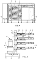
- Fig. 1 illustrates, by way of an example, a chain conveyor of the spiral type, closed in a cold-storage or leavening room 10; the conveyor comprises a support structure 11 for an endless conveyor belt 12 of the chain type, which develops along a spiral path which rises and descends respectively starting from a point 13 of reception of the products to be conveyed towards a transfer point 14, placed substantially at the same level as the previous one.
- One or more drive units 15, shown in figure 2 drive the conveyor belt along its closed path, in the manner specified hereinbelow.
- Each drive device 15 in the example of Fig. 2 substantially comprises a plurality of cogged wheels 16, connected to a vertical shaft 17 which is moved by a ratiomotor 18 via a transmission 19.
- Each cogged wheel 16 is arranged horizontally inside the conveyor belt 12, engaging with one of the ring chains, in the manner illustrated in Fig. 3.
- Each drive wheel 16 is moreover connected coaxially to an underlying cogged wheel 161 supported rotatably by the frame of the conveyor. The cogged wheel 161 in turn engages with a cogged wheel 162 connected to the drive shaft 17.
- the conveyor belt 12 substantially consists of two ring chains 20, 21 which develop parallel along the endless path of the conveyor.
- Each ring of a chain is connected to a corresponding ring of the other chain by cross bars 22 whose ends extend beyond the chains themselves. In this way the various cross bars 22 define the conveying surface of the belt.
- the conveyor belt can develop along rectilinear or curved sections according to the path to be followed.
- the conveyor belt 12 is no longer supported and guided in its sliding by the chains 20 and 21 which now perform the sole function of driving, but instead by longitudinal slide elements 23 and 24 formed for example by suitable plastic section bars. Said slide elements 23, 24 develop substantially for the entire path of the conveyor, only discontinued at the drive wheels 16. In this way the belt 12 slides supported by the same bars 22 whose support points, provided by the section bars 23 and 24, in the case of Figure 3, are situated inside the drive chains, and in any case in a position distanced from the ends of the single bars of the belt.
- Each guide section bar 23 and 24 is supported by the structure 10 of the conveyor, for example by means of appropriate angle bars 25, 26 in the manner shown, fixed to cross bars 27 which join the two lateral edges 28, 29 of the conveyor.
- the slide section bars 23, 24 support the cross bars 22 of the conveyor belt from below as shown. Given that the bars 22 of the belt may rise, or be subject to vibrations, two more longitudinal guide section bars 30, 31 are provided to hold the bars 22 above, along the edges of the conveyor belt.
- the upper restraining section bars 30 and 31 are preferably attached to the downward-bent ends of the two sides 28, 29 of the conveyor, in the manner shown, although other solutions are possible.
- angles 32, Fig. 5, or buffers 33', Fig. 4 have been provided on one of the chains to prevent lateral listing of the chains 20, 21 without causing strong or excessive dragging friction.
- angles 32 may be variously positioned for a rectilinear or curved section of the conveyor, as shown in Figure 5, arranging them on the internal and/or external sides of the chains, or alternatively only for the chain which is positioned on the outside of the curve, discontinuing them or arranging them differently, where necessary, for example at the drive wheels 16.
- Fig. 5 shows a particular arrangement of the chains 20 and 21 placed on the external sides of the guide section bars 23 and 24.
- Fig. 6 of the accompanying drawings instead shows an alternative whereby the ring chains 20 and 21 to which the bars 22 are welded, engage with drive wheels 16' arranged in vertical planes.
- the wheels 16' are connected in pairs to a motor drive unit 15' in the manner indicated schematically.
- Fig. 6 of the drawings also shows a possible different arrangement of the chains 20 and 21 both in relation to the longitudinal guide elements 23 and 24, and in relation to the ends of the cross bars 22.
- Fig. 6 shows a first central arrangement of the chains 20 and 21 on the external sides and in close proximity to the longitudinal guide elements 23 and 24, and a position inside guide elements 23' and 24' and further apart compared to the previous ones.
- the drive means may also act tangentially on a lateral chain of the belt, remaining horizontal and outside of the conveyor as shown in Fig. 7.
- FIG. 7 shows in particular a drive assembly consisting of a first and a second cogged wheel 34, 35 arranged coplanarily one in relation to the other and parallel to the belt on which a closed sprocket chain 36 is wound, said chain having in turn a plurality of hooking teeth 37 equidistant one from the other and hinged to pins 38 of the sprocket chain and extending towards the outside of the sprocket chain.
- Said teeth 37 are inserted, as shown in Figure 7, in the ring elements of one of the lateral chains of the belt.
- This assembly is able to drive the belt with regularity, in that it always has two teeth engaged on the chain of the belt during driving, which avoid the disadvantages caused by systems with a single wheel in which there is a single tooth engaged with the chain of the belt and due to which, when the tooth is detached from the chain and the next tooth is engaged, the motion of the belt becomes irregular.
- the cross bars 22 are attached directly to the vertical rings 20a whereas they are attached to the horizontal rings 20b by means of spacers 33 in order to position the bars 22 as high as possible in relation to the chain or other drive element, or in relation to any other element designed to restrain and guide the driving element of the belt.
- a further feature of the invention shown in Fig. 10, it is possible to provide cross bars 22 with end portions 22a, 22b curved downwards to be attached to respective horizontal rings 20b, 21b in order to define said spacers.
- This solution has the advantage of facilitating assembly of the bars 22 to the chains, in that welding in this case requires the mere attachment of the end tips of the bars to the chains, while the use of separate shims or spacers first requires welding of the latter to the chain and then the attachment of the bars to the spacers; this leads to faster and more economical welding.
- Fig. 6 also shows that the spacers 33 preferably have a rectangular section, which does not create potential friction in that it does not project outside of the rings of the chain. Said shims or spacers nevertheless may have any suitable form whatsoever.
Landscapes
- Engineering & Computer Science (AREA)
- Mechanical Engineering (AREA)
- Chain Conveyers (AREA)
- Framework For Endless Conveyors (AREA)
- Escalators And Moving Walkways (AREA)
- Lubrication Of Internal Combustion Engines (AREA)
- Devices For Conveying Motion By Means Of Endless Flexible Members (AREA)
- Auxiliary Devices For And Details Of Packaging Control (AREA)
- Registering, Tensioning, Guiding Webs, And Rollers Therefor (AREA)
- Intermediate Stations On Conveyors (AREA)
- Structure Of Belt Conveyors (AREA)
Applications Claiming Priority (2)
| Application Number | Priority Date | Filing Date | Title |
|---|---|---|---|
| ITMI930440 | 1993-03-08 | ||
| ITMI930440A IT1271991B (it) | 1993-03-08 | 1993-03-08 | Convongliatore a catene perfezionato |
Publications (2)
| Publication Number | Publication Date |
|---|---|
| EP0614831A1 true EP0614831A1 (de) | 1994-09-14 |
| EP0614831B1 EP0614831B1 (de) | 1998-06-24 |
Family
ID=11365279
Family Applications (1)
| Application Number | Title | Priority Date | Filing Date |
|---|---|---|---|
| EP94102880A Expired - Lifetime EP0614831B1 (de) | 1993-03-08 | 1994-02-25 | Kettenförderer |
Country Status (6)
| Country | Link |
|---|---|
| US (1) | US5454467A (de) |
| EP (1) | EP0614831B1 (de) |
| AT (1) | ATE167651T1 (de) |
| DE (1) | DE69411210T2 (de) |
| ES (1) | ES2120524T3 (de) |
| IT (1) | IT1271991B (de) |
Cited By (3)
| Publication number | Priority date | Publication date | Assignee | Title |
|---|---|---|---|---|
| EP1724217A2 (de) | 2004-06-24 | 2006-11-22 | Alit S.r.l. | Antriebsvorrichtung für ein eine Förderkette aufweisendes Förderband |
| EP2347979A1 (de) * | 2009-05-08 | 2011-07-27 | Alit S.r.l. | Vorrichtung zur Übertragung von Antriebsbewegung für Bandförderer |
| DE102020004666B3 (de) | 2020-07-31 | 2021-07-15 | Lipsia Automation GmbH | Trommelantrieb für rotierende Trommeln |
Families Citing this family (16)
| Publication number | Priority date | Publication date | Assignee | Title |
|---|---|---|---|---|
| IT1273734B (it) * | 1994-07-22 | 1997-07-09 | Tecno Pool Spa | Convogliatore a catene con dispositivo di guida migliorato |
| US5779027A (en) * | 1996-02-14 | 1998-07-14 | Rexnord Corporation | Sideflexing conveyor including lubrication inserts |
| US5992615A (en) * | 1998-01-12 | 1999-11-30 | Muchalov; Ivan | Curved conveyor section |
| US6227355B1 (en) | 1999-05-24 | 2001-05-08 | Stainless Steel Systems, Inc. | Sanitary conveyor apparatus |
| IT1315694B1 (it) * | 2000-05-16 | 2003-03-18 | Alit Srl | Struttura di trasportatore flessibile a catena |
| US6796418B1 (en) * | 2003-06-26 | 2004-09-28 | Kvp Corporation | Addition of intermediate supports for spiral conveyors |
| US7246697B2 (en) * | 2004-11-08 | 2007-07-24 | Dorner Mfg. Corp. | Washdown conveyor corner section with removable wear strips |
| NL2001010C2 (nl) * | 2007-11-16 | 2009-05-19 | Kaak Johan H B | Spiraaltransporteur. |
| KR20120091048A (ko) * | 2009-09-04 | 2012-08-17 | 라이트람, 엘엘씨 | 스파이럴 컨베이어 시스템 및 방법 |
| USD658842S1 (en) | 2011-08-24 | 2012-05-01 | Span Tech Llc | Spiral conveyor frame |
| WO2013074759A1 (en) * | 2011-11-15 | 2013-05-23 | Span Tech Llc | Conveyor disabler and related methods |
| CN102602661A (zh) * | 2012-03-26 | 2012-07-25 | 肇庆市珊瑚食品机械有限公司 | 旋转输送装置 |
| DE202012104466U1 (de) * | 2012-11-19 | 2013-05-28 | Krones Ag | Vorrichtung zum Bereitstellen von Formteilen in einer Getränkeabfüllanlage |
| US9884723B2 (en) | 2015-07-24 | 2018-02-06 | Ashworth Bros., Inc. | Spiral conveyor system |
| US9669998B2 (en) | 2015-08-12 | 2017-06-06 | Ivan Muchalov | Conveyor drive system |
| JP6506868B1 (ja) * | 2018-04-25 | 2019-04-24 | 米田工機株式会社 | 食品加工処理装置および食品加工処理方法 |
Citations (9)
| Publication number | Priority date | Publication date | Assignee | Title |
|---|---|---|---|---|
| US2877888A (en) * | 1956-01-03 | 1959-03-17 | Baker Perkins Inc | Conveyor belt |
| US3237756A (en) * | 1961-03-09 | 1966-03-01 | Velten & Pulver | Conveyor structure |
| US3270863A (en) * | 1964-06-22 | 1966-09-06 | Virgil E Ackles | Conveyor driving unit |
| US4040302A (en) * | 1975-01-03 | 1977-08-09 | Mitsubishi Jukogyo Kabushiki Kaisha | Chain drive for a transfer machine |
| US4244464A (en) * | 1979-12-05 | 1981-01-13 | Gebr. Van Capelleveen B.V. | Conveyor, in particular for eggs |
| GB2108459A (en) * | 1981-10-23 | 1983-05-18 | Facco Impianti Avicoli Srl | Guide track for a chain conveyor |
| DE8623146U1 (de) * | 1986-08-27 | 1986-10-09 | Rud-Kettenfabrik Rieger & Dietz Gmbh U. Co, 73432 Aalen | Kettenförderer |
| US4850475A (en) * | 1987-07-14 | 1989-07-25 | Joseph Lupo | Conveyor system including a chain drive for driving an endless belt in tensioned condition |
| EP0544085A1 (de) * | 1991-11-27 | 1993-06-02 | TECNO POOL S.p.A. | Kettenfördererantrieb |
Family Cites Families (4)
| Publication number | Priority date | Publication date | Assignee | Title |
|---|---|---|---|---|
| US2446890A (en) * | 1946-10-21 | 1948-08-10 | Latendorf Conveying Corp | Lateral bend power-driven conveyer |
| US2800218A (en) * | 1956-09-14 | 1957-07-23 | Drouin Alphonse | Lateral bend conveyor |
| US2990052A (en) * | 1957-11-18 | 1961-06-27 | Stockholms Bageriaktiebolag | Conveyor |
| JPH05132115A (ja) * | 1991-11-12 | 1993-05-28 | Kawasaki Seisakusho:Kk | スパイラルコンベア |
-
1993
- 1993-03-08 IT ITMI930440A patent/IT1271991B/it active IP Right Grant
-
1994
- 1994-02-25 AT AT94102880T patent/ATE167651T1/de not_active IP Right Cessation
- 1994-02-25 EP EP94102880A patent/EP0614831B1/de not_active Expired - Lifetime
- 1994-02-25 ES ES94102880T patent/ES2120524T3/es not_active Expired - Lifetime
- 1994-02-25 DE DE69411210T patent/DE69411210T2/de not_active Expired - Fee Related
- 1994-03-04 US US08/205,728 patent/US5454467A/en not_active Expired - Fee Related
Patent Citations (9)
| Publication number | Priority date | Publication date | Assignee | Title |
|---|---|---|---|---|
| US2877888A (en) * | 1956-01-03 | 1959-03-17 | Baker Perkins Inc | Conveyor belt |
| US3237756A (en) * | 1961-03-09 | 1966-03-01 | Velten & Pulver | Conveyor structure |
| US3270863A (en) * | 1964-06-22 | 1966-09-06 | Virgil E Ackles | Conveyor driving unit |
| US4040302A (en) * | 1975-01-03 | 1977-08-09 | Mitsubishi Jukogyo Kabushiki Kaisha | Chain drive for a transfer machine |
| US4244464A (en) * | 1979-12-05 | 1981-01-13 | Gebr. Van Capelleveen B.V. | Conveyor, in particular for eggs |
| GB2108459A (en) * | 1981-10-23 | 1983-05-18 | Facco Impianti Avicoli Srl | Guide track for a chain conveyor |
| DE8623146U1 (de) * | 1986-08-27 | 1986-10-09 | Rud-Kettenfabrik Rieger & Dietz Gmbh U. Co, 73432 Aalen | Kettenförderer |
| US4850475A (en) * | 1987-07-14 | 1989-07-25 | Joseph Lupo | Conveyor system including a chain drive for driving an endless belt in tensioned condition |
| EP0544085A1 (de) * | 1991-11-27 | 1993-06-02 | TECNO POOL S.p.A. | Kettenfördererantrieb |
Cited By (6)
| Publication number | Priority date | Publication date | Assignee | Title |
|---|---|---|---|---|
| EP1724217A2 (de) | 2004-06-24 | 2006-11-22 | Alit S.r.l. | Antriebsvorrichtung für ein eine Förderkette aufweisendes Förderband |
| EP1724217A3 (de) * | 2004-06-24 | 2006-11-29 | Alit S.r.l. | Antriebsvorrichtung für ein eine Förderkette aufweisendes Förderband |
| US7258227B2 (en) | 2004-06-24 | 2007-08-21 | Alit S.R.L. | Drive for conveyor belts |
| EP2347979A1 (de) * | 2009-05-08 | 2011-07-27 | Alit S.r.l. | Vorrichtung zur Übertragung von Antriebsbewegung für Bandförderer |
| DE102020004666B3 (de) | 2020-07-31 | 2021-07-15 | Lipsia Automation GmbH | Trommelantrieb für rotierende Trommeln |
| WO2022022878A1 (de) | 2020-07-31 | 2022-02-03 | Lipsia Automation GmbH | Trommelantrieb für rotierende trommeln |
Also Published As
| Publication number | Publication date |
|---|---|
| DE69411210D1 (de) | 1998-07-30 |
| ES2120524T3 (es) | 1998-11-01 |
| US5454467A (en) | 1995-10-03 |
| ITMI930440A0 (it) | 1993-03-08 |
| EP0614831B1 (de) | 1998-06-24 |
| DE69411210T2 (de) | 1999-03-04 |
| ATE167651T1 (de) | 1998-07-15 |
| ITMI930440A1 (it) | 1994-09-08 |
| IT1271991B (it) | 1997-06-10 |
Similar Documents
| Publication | Publication Date | Title |
|---|---|---|
| US5454467A (en) | Chain conveyor | |
| EP0717717B1 (de) | Kontinuierlicher senkrechtförderer | |
| JP3665645B2 (ja) | 高速度収納装置 | |
| US3682295A (en) | Edge driven conveyor system | |
| US6176367B1 (en) | Device for conveyance along assembly lines and the like | |
| US7063202B2 (en) | Moving walkway | |
| US4142625A (en) | Holding conveyor system | |
| US4040302A (en) | Chain drive for a transfer machine | |
| SU1170977A3 (ru) | Цепь дл механизма подачи горной машины | |
| US3450250A (en) | Conveyor system | |
| KR100523682B1 (ko) | 컨베이어 장치 | |
| US3297127A (en) | Continuously moving stairway | |
| EP0693444B1 (de) | Kettenförderer mit verbesserter Führung | |
| US3045808A (en) | Chain conveyor | |
| DE59800403D1 (de) | Fördervorrichtung für regalkanäle von regallageranlagen | |
| US6009993A (en) | Bucket conveyor apparatus having improved infeed station | |
| JP2631897B2 (ja) | 自動倉庫 | |
| US7217079B2 (en) | Slide fork | |
| JPS5932363B2 (ja) | 連続移動する製品処理装置で製品を搬送する無端チエ−ン | |
| US3252564A (en) | Conveyor systems | |
| CN212475000U (zh) | 一种新型高效移载系统 | |
| JP2684571B2 (ja) | パレットの移載装置 | |
| JPS59223623A (ja) | 無端コンベヤ装置上の荷物の方向変更装置 | |
| RU2255031C1 (ru) | Кольцевой конвейер | |
| US3537572A (en) | Belt structure |
Legal Events
| Date | Code | Title | Description |
|---|---|---|---|
| PUAI | Public reference made under article 153(3) epc to a published international application that has entered the european phase |
Free format text: ORIGINAL CODE: 0009012 |
|
| AK | Designated contracting states |
Kind code of ref document: A1 Designated state(s): AT BE CH DE DK ES FR GB GR IE IT LI LU MC NL PT SE |
|
| 17P | Request for examination filed |
Effective date: 19950217 |
|
| 17Q | First examination report despatched |
Effective date: 19960228 |
|
| GRAG | Despatch of communication of intention to grant |
Free format text: ORIGINAL CODE: EPIDOS AGRA |
|
| GRAG | Despatch of communication of intention to grant |
Free format text: ORIGINAL CODE: EPIDOS AGRA |
|
| GRAH | Despatch of communication of intention to grant a patent |
Free format text: ORIGINAL CODE: EPIDOS IGRA |
|
| GRAH | Despatch of communication of intention to grant a patent |
Free format text: ORIGINAL CODE: EPIDOS IGRA |
|
| GRAA | (expected) grant |
Free format text: ORIGINAL CODE: 0009210 |
|
| AK | Designated contracting states |
Kind code of ref document: B1 Designated state(s): AT BE CH DE DK ES FR GB GR IE IT LI LU MC NL PT SE |
|
| PG25 | Lapsed in a contracting state [announced via postgrant information from national office to epo] |
Ref country code: LI Free format text: LAPSE BECAUSE OF FAILURE TO SUBMIT A TRANSLATION OF THE DESCRIPTION OR TO PAY THE FEE WITHIN THE PRESCRIBED TIME-LIMIT Effective date: 19980624 Ref country code: GR Free format text: LAPSE BECAUSE OF NON-PAYMENT OF DUE FEES Effective date: 19980624 Ref country code: CH Free format text: LAPSE BECAUSE OF FAILURE TO SUBMIT A TRANSLATION OF THE DESCRIPTION OR TO PAY THE FEE WITHIN THE PRESCRIBED TIME-LIMIT Effective date: 19980624 Ref country code: BE Free format text: LAPSE BECAUSE OF FAILURE TO SUBMIT A TRANSLATION OF THE DESCRIPTION OR TO PAY THE FEE WITHIN THE PRESCRIBED TIME-LIMIT Effective date: 19980624 Ref country code: AT Free format text: LAPSE BECAUSE OF FAILURE TO SUBMIT A TRANSLATION OF THE DESCRIPTION OR TO PAY THE FEE WITHIN THE PRESCRIBED TIME-LIMIT Effective date: 19980624 |
|
| REF | Corresponds to: |
Ref document number: 167651 Country of ref document: AT Date of ref document: 19980715 Kind code of ref document: T |
|
| REG | Reference to a national code |
Ref country code: CH Ref legal event code: EP |
|
| REF | Corresponds to: |
Ref document number: 69411210 Country of ref document: DE Date of ref document: 19980730 |
|
| REG | Reference to a national code |
Ref country code: IE Ref legal event code: FG4D |
|
| PG25 | Lapsed in a contracting state [announced via postgrant information from national office to epo] |
Ref country code: SE Free format text: LAPSE BECAUSE OF FAILURE TO SUBMIT A TRANSLATION OF THE DESCRIPTION OR TO PAY THE FEE WITHIN THE PRESCRIBED TIME-LIMIT Effective date: 19980924 Ref country code: PT Free format text: LAPSE BECAUSE OF FAILURE TO SUBMIT A TRANSLATION OF THE DESCRIPTION OR TO PAY THE FEE WITHIN THE PRESCRIBED TIME-LIMIT Effective date: 19980924 Ref country code: DK Free format text: LAPSE BECAUSE OF FAILURE TO SUBMIT A TRANSLATION OF THE DESCRIPTION OR TO PAY THE FEE WITHIN THE PRESCRIBED TIME-LIMIT Effective date: 19980924 |
|
| REG | Reference to a national code |
Ref country code: ES Ref legal event code: FG2A Ref document number: 2120524 Country of ref document: ES Kind code of ref document: T3 |
|
| ET | Fr: translation filed | ||
| REG | Reference to a national code |
Ref country code: CH Ref legal event code: PL |
|
| RAP2 | Party data changed (patent owner data changed or rights of a patent transferred) |
Owner name: TECNO POOL S.P.A. |
|
| PG25 | Lapsed in a contracting state [announced via postgrant information from national office to epo] |
Ref country code: LU Free format text: LAPSE BECAUSE OF NON-PAYMENT OF DUE FEES Effective date: 19990225 Ref country code: IE Free format text: LAPSE BECAUSE OF NON-PAYMENT OF DUE FEES Effective date: 19990225 |
|
| NLT2 | Nl: modifications (of names), taken from the european patent patent bulletin |
Owner name: TECNO POOL S.P.A. |
|
| PLBE | No opposition filed within time limit |
Free format text: ORIGINAL CODE: 0009261 |
|
| STAA | Information on the status of an ep patent application or granted ep patent |
Free format text: STATUS: NO OPPOSITION FILED WITHIN TIME LIMIT |
|
| 26N | No opposition filed | ||
| PG25 | Lapsed in a contracting state [announced via postgrant information from national office to epo] |
Ref country code: MC Free format text: LAPSE BECAUSE OF NON-PAYMENT OF DUE FEES Effective date: 19990831 |
|
| REG | Reference to a national code |
Ref country code: IE Ref legal event code: MM4A |
|
| PGFP | Annual fee paid to national office [announced via postgrant information from national office to epo] |
Ref country code: GB Payment date: 20010219 Year of fee payment: 8 |
|
| PGFP | Annual fee paid to national office [announced via postgrant information from national office to epo] |
Ref country code: ES Payment date: 20010222 Year of fee payment: 8 |
|
| PGFP | Annual fee paid to national office [announced via postgrant information from national office to epo] |
Ref country code: NL Payment date: 20010227 Year of fee payment: 8 Ref country code: FR Payment date: 20010227 Year of fee payment: 8 |
|
| PGFP | Annual fee paid to national office [announced via postgrant information from national office to epo] |
Ref country code: DE Payment date: 20010228 Year of fee payment: 8 |
|
| REG | Reference to a national code |
Ref country code: GB Ref legal event code: IF02 |
|
| PG25 | Lapsed in a contracting state [announced via postgrant information from national office to epo] |
Ref country code: GB Free format text: LAPSE BECAUSE OF NON-PAYMENT OF DUE FEES Effective date: 20020225 |
|
| PG25 | Lapsed in a contracting state [announced via postgrant information from national office to epo] |
Ref country code: ES Free format text: LAPSE BECAUSE OF NON-PAYMENT OF DUE FEES Effective date: 20020226 |
|
| PG25 | Lapsed in a contracting state [announced via postgrant information from national office to epo] |
Ref country code: NL Free format text: LAPSE BECAUSE OF NON-PAYMENT OF DUE FEES Effective date: 20020901 |
|
| PG25 | Lapsed in a contracting state [announced via postgrant information from national office to epo] |
Ref country code: DE Free format text: LAPSE BECAUSE OF NON-PAYMENT OF DUE FEES Effective date: 20020903 |
|
| GBPC | Gb: european patent ceased through non-payment of renewal fee |
Effective date: 20020225 |
|
| PG25 | Lapsed in a contracting state [announced via postgrant information from national office to epo] |
Ref country code: FR Free format text: LAPSE BECAUSE OF NON-PAYMENT OF DUE FEES Effective date: 20021031 |
|
| NLV4 | Nl: lapsed or anulled due to non-payment of the annual fee |
Effective date: 20020901 |
|
| REG | Reference to a national code |
Ref country code: FR Ref legal event code: ST |
|
| REG | Reference to a national code |
Ref country code: ES Ref legal event code: FD2A Effective date: 20031122 |
|
| PGFP | Annual fee paid to national office [announced via postgrant information from national office to epo] |
Ref country code: IT Payment date: 20060228 Year of fee payment: 13 |
|
| PG25 | Lapsed in a contracting state [announced via postgrant information from national office to epo] |
Ref country code: IT Free format text: LAPSE BECAUSE OF NON-PAYMENT OF DUE FEES Effective date: 20070225 |