EP0615046A2 - Procédé pour le remplissage partiel de corps creux avec granulat - Google Patents
Procédé pour le remplissage partiel de corps creux avec granulat Download PDFInfo
- Publication number
- EP0615046A2 EP0615046A2 EP94890013A EP94890013A EP0615046A2 EP 0615046 A2 EP0615046 A2 EP 0615046A2 EP 94890013 A EP94890013 A EP 94890013A EP 94890013 A EP94890013 A EP 94890013A EP 0615046 A2 EP0615046 A2 EP 0615046A2
- Authority
- EP
- European Patent Office
- Prior art keywords
- probe
- granules
- frame
- hollow body
- filled
- Prior art date
- Legal status (The legal status is an assumption and is not a legal conclusion. Google has not performed a legal analysis and makes no representation as to the accuracy of the status listed.)
- Granted
Links
Images
Classifications
-
- E—FIXED CONSTRUCTIONS
- E06—DOORS, WINDOWS, SHUTTERS, OR ROLLER BLINDS IN GENERAL; LADDERS
- E06B—FIXED OR MOVABLE CLOSURES FOR OPENINGS IN BUILDINGS, VEHICLES, FENCES OR LIKE ENCLOSURES IN GENERAL, e.g. DOORS, WINDOWS, BLINDS, GATES
- E06B3/00—Window sashes, door leaves, or like elements for closing wall or like openings; Layout of fixed or moving closures, e.g. windows in wall or like openings; Features of rigidly-mounted outer frames relating to the mounting of wing frames
- E06B3/66—Units comprising two or more parallel glass or like panes permanently secured together
- E06B3/673—Assembling the units
- E06B3/67304—Preparing rigid spacer members before assembly
- E06B3/67317—Filling of hollow spacer elements with absorbants; Closing off the spacers thereafter
-
- G—PHYSICS
- G01—MEASURING; TESTING
- G01F—MEASURING VOLUME, VOLUME FLOW, MASS FLOW OR LIQUID LEVEL; METERING BY VOLUME
- G01F23/00—Indicating or measuring liquid level or level of fluent solid material, e.g. indicating in terms of volume or indicating by means of an alarm
- G01F23/0007—Indicating or measuring liquid level or level of fluent solid material, e.g. indicating in terms of volume or indicating by means of an alarm for discrete indicating and measuring
-
- Y—GENERAL TAGGING OF NEW TECHNOLOGICAL DEVELOPMENTS; GENERAL TAGGING OF CROSS-SECTIONAL TECHNOLOGIES SPANNING OVER SEVERAL SECTIONS OF THE IPC; TECHNICAL SUBJECTS COVERED BY FORMER USPC CROSS-REFERENCE ART COLLECTIONS [XRACs] AND DIGESTS
- Y10—TECHNICAL SUBJECTS COVERED BY FORMER USPC
- Y10T—TECHNICAL SUBJECTS COVERED BY FORMER US CLASSIFICATION
- Y10T29/00—Metal working
- Y10T29/49—Method of mechanical manufacture
- Y10T29/49764—Method of mechanical manufacture with testing or indicating
-
- Y—GENERAL TAGGING OF NEW TECHNOLOGICAL DEVELOPMENTS; GENERAL TAGGING OF CROSS-SECTIONAL TECHNOLOGIES SPANNING OVER SEVERAL SECTIONS OF THE IPC; TECHNICAL SUBJECTS COVERED BY FORMER USPC CROSS-REFERENCE ART COLLECTIONS [XRACs] AND DIGESTS
- Y10—TECHNICAL SUBJECTS COVERED BY FORMER USPC
- Y10T—TECHNICAL SUBJECTS COVERED BY FORMER US CLASSIFICATION
- Y10T29/00—Metal working
- Y10T29/53—Means to assemble or disassemble
- Y10T29/53039—Means to assemble or disassemble with control means energized in response to activator stimulated by condition sensor
-
- Y—GENERAL TAGGING OF NEW TECHNOLOGICAL DEVELOPMENTS; GENERAL TAGGING OF CROSS-SECTIONAL TECHNOLOGIES SPANNING OVER SEVERAL SECTIONS OF THE IPC; TECHNICAL SUBJECTS COVERED BY FORMER USPC CROSS-REFERENCE ART COLLECTIONS [XRACs] AND DIGESTS
- Y10—TECHNICAL SUBJECTS COVERED BY FORMER USPC
- Y10T—TECHNICAL SUBJECTS COVERED BY FORMER US CLASSIFICATION
- Y10T29/00—Metal working
- Y10T29/53—Means to assemble or disassemble
- Y10T29/53039—Means to assemble or disassemble with control means energized in response to activator stimulated by condition sensor
- Y10T29/53061—Responsive to work or work-related machine element
Definitions
- the invention relates to a method for partially filling hollow bodies with granules and a device for carrying out this method.
- spacer frames for insulating glass panes which consist of one or more pieces of hollow profile strips, with granular desiccant (molecular sieve)
- the problem often arises that the hollow profile strip (s) forming the spacer must not be filled to the end, to enable the connection of the hollow profile strip, for example by inserting straight connectors or corner connectors.
- the invention has for its object to provide a method of the type mentioned, with the hollow body, in particular hollow profile strips for spacer frames for insulating glass panes, without further ado only to the desired fill level, i.e. can be partially filled.
- this object is achieved in that a probe connected to a granulate storage container is inserted into the hollow body to such an extent that its front end is arranged in the hollow body at the point up to which the latter is to be filled with granulate that the Feeding of granules is stopped as soon as the hollow body has been filled with granules up to the front end of the probe, and the probe is then pulled out of the hollow body.
- Preferred embodiments of the method according to the invention are the subject of dependent claims 2 to 4.
- the application of the method according to the invention is very particularly preferred for filling spacer frames having three corners, which consist of at least one hollow profile strip, the fourth corner of which is still open, the fourth corner being able to be formed in that one of the two frame legs leading to the open corner is longer than the other and is bent, the free end then coming to rest next to the free end of the shorter frame leg.
- the invention is also advantageous for spacer frames in which at least one, e.g. the fourth corner is closed by inserting a corner bracket.
- the hollow profile strip must not be completely filled with desiccant.
- the longer leg may only be filled to below the bending area in order to complete the bending process not adversely affected (danger that the hollow profile bursts or desiccant is crushed into powder). Even if the fourth corner is closed with the help of a corner bracket, both legs must not be completely filled so that the corner bracket can be inserted.
- the shorter frame leg may also, if the last corner, e.g. the fourth corner of a spacer frame is formed by bending the longer frame leg, not to be completely filled when the frame is closed using a straight connector inserted into the open ends, as is known per se from US-A-4 912 837, or by butt welding (see US-A-4 704 512).
- the spacer frame for insulating glass panes formed from at least one hollow profile strip with granular drying agent
- the spacer frame having several, e.g. has three corners, preferably formed by bending, and at the last corner to be formed, e.g.
- the fourth corner is left open, granular desiccant being poured in via the open ends of one or both frame legs leading to this open position and then the frame being finally closed, preferably one frame leg being longer than the other and the elongated frame leg being below its bending point and / or the shortened frame leg are partially filled, then it is preferably carried out in such a way that the method according to one or more of claims 1 to 4 is applied, and that the frame after the filling process after bending the longer frame leg at the bending point by a straight connector or is closed by welding the open ends.
- the invention further extends to a method variant in which the movement of granules in the probe is monitored and the filling process is stopped as soon as the movement of granules in the probe stops.
- This variant of the method of the invention can be further developed by monitoring the movement of granules by means of a movement sensor assigned to the line or the probe.
- a device which is particularly suitable for carrying out the method according to the invention with a storage container for granules and a holder for the hollow body to be filled can be characterized according to the invention in that at least one probe which can be inserted into the hollow body to be filled is provided such that the probe is connected to the storage container via a line for granules, the line or the probe is assigned a sensor for monitoring movements of the granules and that a line for applying negative pressure is connected to the probe at a distance from its free end.
- the method and the device according to the invention are based on the knowledge that the inflow of granules through the probe into the hollow body, which is, for example, a hollow profile strip for spacer frames of insulating glass, automatically stops when the filled granulate enters the end of the probe inserted into the hollow body has reached. If the movement of granules in the probe or in a line upstream of it is monitored, the cessation of movement of granules in the probe or the feed line can be used to generate a control signal which e.g. completed the filling process.
- the inflow of granules through the probe into the hollow body which is, for example, a hollow profile strip for spacer frames of insulating glass
- negative pressure is applied to the probe while it is pulled out of the hollow body and kept ready for insertion into the next hollow body to be filled, granules contained in the probe are prevented from flowing out of the latter and either gets lost or fills the hollow body further than is desired.
- Applying negative pressure causes that Granulate wedged like a plug between the connection point of the vacuum line and the open end of the probe, so that no or practically no granulate can flow out of the probe. If the negative pressure is released again, the wedging is eliminated, the plug disintegrates and granulate can flow back into a hollow body or a hollow profile strip.
- the extent and depth with which the probe is inserted into a hollow body or into a hollow profile strip can be adjusted in various ways. Either the advance of the probe is monitored by a displacement measuring device when it is inserted into the hollow body, or a stop is provided which limits the depth of insertion of the probe into the hollow body or into the hollow profile strip.
- This stop can be a stop that lies against the front free end of the hollow body or the hollow profile strip, which is to be filled with granules.
- the stop can also be adjustable to the insertion depth, i.e. adjust the extent to which the hollow body or the hollow profile strip is filled with granules to the desired size.
- spacer frames for example, can be filled with granular desiccant containing three Corners are bent and the fourth corner is still open.
- Such spacer frames can be produced, for example, in the bending device known from US-A-5 136 871, the bending of the fourth corner described in US-A-5 136 871 to close the spacer initially being omitted. Then one of the two legs 2 of the spacer frame 1 leading to the still open corner protrudes beyond the fourth corner to be made by the piece 5, by which the other leg 3 of the spacer frame 1 leading to the corner still to be made is shorter.
- hollow profile strips for spacer frames or spacer frames can be filled by the method according to the invention or in the device according to the invention, the corners of which are all or only partially formed by corner connectors inserted into the hollow profile strip sections.
- the working technique according to the invention can be advantageously used wherever relatively narrow hollow bodies, i.e. to be filled to a desired extent (filling level) with granular material.
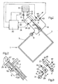
- the device shown in Fig. 1 consists of an arbitrarily designed bracket 6, 7 for the spacer frame 1, wherein the brackets 6,7 are designed, for example, as clamps which grip the legs 2 and 3 of the spacer frame 1 leading to the open corner.
- the device according to the invention also has a storage container 10 for granular desiccant which is to be filled into the spacer frame 1.
- the granular desiccant is via lines 11, 12 of shut-off devices 13, 14 regulated, led to two probes 20 and 21, which are inserted with their free ends in the legs 2 and 3 of the spacer frame 1 when the spacer frame 1 is to be filled with granular desiccant.
- two sensors 26 and 27 are arranged, which detect the movement of granular desiccant in the Detect lines 11, 12 and thus through the probes 20, 21 and emit a signal when the movement of granular desiccant stops. Examples of suitable sensors are described in US-A-4 670 954 or in USA-5 134 279.
- the device further comprises a controller 30, which among other things. Receives signals via the lines 31, 32 from the sensors 26, 27 mentioned and which in turn controls the shut-off devices 13, 14 in the lines 11, 12.
- lines can be connected to the lines 11, 12 or to the probes 20, 21, through which lines the flow of granular desiccant through the lines 11, 12 and through the probes 20, 21 in the legs 2 and 3 of the spacer frame 1 supporting gas, for example dried air can be blown in.
- Lines 40, 41 which lead to a vacuum source, are connected to the probes 20 and / or 21.
- Shut-off devices 42, 43 are provided in the lines 40, 41, the opening and closing movements of which are also controlled by the controller 30.
- FIG. 2 shows the probe 20 again on an enlarged scale.
- FIG. 2 also shows that in the region of the mouth of the line 40, which leads to the vacuum source, a gas- or air-permeable material at the probe 20, but the passage of granular material preventing plate 44 such as a sieve or the like is provided.
- the plate 44 prevents the creation of Vacuum to line 40, ie granular desiccant is sucked into the line 40 from the interior of the probe 20 when the shut-off element 42 is open.
- Fig. 2 also shows that the insertion depth X of the probe 20 in the leg 2 of the spacer frame 1 can be determined by a stop 50 which is adjustable in the embodiment shown by a pressure medium motor 51 (arrow 52).
- a stop 50 for limiting the insertion depth X of the probe 20 in the leg 2
- fixed stops or measuring devices can also be provided, which measure the advance of the holder 25 with the probe 20 when the probe 20 is inserted into the leg 2 and after it has been reached the feed depth X at the desired insertion depth.
- the probe 20 is inserted into the leg 2 so far that its free front end from the open end 2 'of Leg 2, through which the probe 20 has been inserted, has a distance X which is slightly greater than the length of the section 5 of the leg 2, which is to be bent at the point 4 to form the corner.
- FIG 3 shows another embodiment of the device according to the invention, in which the two probes 20 and 21 are provided on separate brackets 25 and 25 '.
- This embodiment has the advantage that the probes 20 and 21 can be inserted independently into the legs 2 and 3 of a spacer frame 1 leading to the open corner. This is important, for example, if the leg 3 of the spacer frame 1 is not to be completely filled with granular desiccant in order not to impede the butt welding process, or to engage a straight connector to finally close the spacer frame 1 after bending the To allow section 5 of the frame leg 2.
- the spacer frame 1 is inserted manually or mechanically into the device and held in place by the clamps 6 and 7.
- the spacer frame 1 is preferably aligned so that it is aligned substantially vertically, with the corner still open facing upwards.
- the probes 20 and 21 are inserted into the open ends of the legs 2 and 3 leading to the open corner until the front ends of the probes 20 and 21 protrude into the legs 2 and 3 up to the point where the legs 2 and 3 are filled with granular desiccant. This is shown in FIG. 2 for the probe 20, the insertion depth of the probe 20 being the distance X there.
- the probes 20 and 21 are pulled out of the open ends of the legs 2 and 3 of the spacer frame 1 while the negative pressure is still applied to them.
- the spacer frame 1 thus filled with granular desiccant is now further processed by forming the fourth corner by bending section 5 of the leg 2 (e.g. immediately in the device by means of a bending device, not shown, see US-A-4 912 837). Now the spacer frame is closed, the connection of the free ends of the hollow gusset forming the spacer frame 1 either by a straight connector (see US-A-4 912 837), or by means of a welding device (see US-A-4 704 512) Filling device or a downstream device can be performed.
- hollow bodies for example legs of spacer frames or also hollow profile strips for producing spacer frames, can be filled with granular material - in the case of spacer frames granular desiccant - precisely to the desired filling level without any particular effort.
- the procedure according to the invention and the device according to the invention offer considerable advantages over the filling of a predetermined amount into the spacer frame or the time-dependent filling in order to achieve a metered filling which only partially fills the hollow body, since they cause errors due to losses of granular material or changes avoids the flow velocity of the granular material and always takes the actual filling level into account.
- the method according to the invention avoids that, for example, spacer frames for insulating glass panes are filled too much or too little.
- the method according to the invention can also be carried out in a correspondingly equipped device for producing spacer frames for insulating glass panes by repeatedly bending hollow profile strips.
- the described device of the invention can be easily integrated into a device for producing spacer frames by bending hollow profile strips.
- the invention can be represented as follows, for example:
- a spacer frame which consists of a hollow profile strip bent three times and is still open at the fourth corner, one leg 2 being longer than the other leg leading to the open corner, is filled with granular desiccant via a probe 20 inserted into the leg 2.
- the front end of the probe 20 projects into the leg 2 to the desired filling level.
- the sensor 27 controls the extraction of the probe 20. In this case, vacuum is applied to the probe 20 via a line 40, so that no more desiccant emerges from the probe 20.
Landscapes
- Engineering & Computer Science (AREA)
- Civil Engineering (AREA)
- Structural Engineering (AREA)
- Physics & Mathematics (AREA)
- Fluid Mechanics (AREA)
- General Physics & Mathematics (AREA)
- Basic Packing Technique (AREA)
- Securing Of Glass Panes Or The Like (AREA)
- Processing And Handling Of Plastics And Other Materials For Molding In General (AREA)
- Medical Preparation Storing Or Oral Administration Devices (AREA)
- Manufacturing Of Micro-Capsules (AREA)
Applications Claiming Priority (2)
| Application Number | Priority Date | Filing Date | Title |
|---|---|---|---|
| AT0048993A AT399501B (de) | 1993-03-12 | 1993-03-12 | Verfahren zum teilweisen füllen von hohlkörpern mit granulat und vorrichtung zur durchführung des verfahrens |
| AT489/93 | 1993-03-12 |
Publications (3)
| Publication Number | Publication Date |
|---|---|
| EP0615046A2 true EP0615046A2 (fr) | 1994-09-14 |
| EP0615046A3 EP0615046A3 (fr) | 1995-05-24 |
| EP0615046B1 EP0615046B1 (fr) | 1997-05-28 |
Family
ID=3491968
Family Applications (1)
| Application Number | Title | Priority Date | Filing Date |
|---|---|---|---|
| EP94890013A Expired - Lifetime EP0615046B1 (fr) | 1993-03-12 | 1994-01-19 | Procédé pour le remplissage partiel de corps creux avec granulat |
Country Status (5)
| Country | Link |
|---|---|
| US (1) | US5390406A (fr) |
| EP (1) | EP0615046B1 (fr) |
| AT (2) | AT399501B (fr) |
| DE (3) | DE59402864D1 (fr) |
| ES (1) | ES2102800T3 (fr) |
Cited By (2)
| Publication number | Priority date | Publication date | Assignee | Title |
|---|---|---|---|---|
| WO2021005149A1 (fr) | 2019-07-11 | 2021-01-14 | Lisec Austria Gmbh | Procédé et dispositif de remplissage de baguettes profilées creuses |
| WO2024132428A1 (fr) | 2022-12-19 | 2024-06-27 | Lisec Austria Gmbh | Procédé et dispositif de remplissage de profilés creux avec un matériau de remplissage |
Families Citing this family (3)
| Publication number | Priority date | Publication date | Assignee | Title |
|---|---|---|---|---|
| USD443145S1 (en) | 1999-08-18 | 2001-06-05 | Omnova Wallcovering (Uk) Limited | Light-reflective wall covering |
| US6622456B2 (en) * | 2001-11-06 | 2003-09-23 | Truseal Telenologies, Inc. | Method and apparatus for filling the inner space of insulating glass units with inert gases |
| WO2009064919A1 (fr) * | 2007-11-13 | 2009-05-22 | Infinite Edge Technologies, Llc | Écarteur sous forme de boîtier pourvu de parois latérales |
Family Cites Families (17)
| Publication number | Priority date | Publication date | Assignee | Title |
|---|---|---|---|---|
| US3624628A (en) * | 1969-11-24 | 1971-11-30 | Mc Graw Edison Co | Battery-filling apparatus with electronic signaling unit |
| US3799622A (en) * | 1971-12-28 | 1974-03-26 | Universal Dynamics Corp | Multi-station loader for particulate material |
| US3841138A (en) * | 1972-10-25 | 1974-10-15 | Reynolds Metals Co | Apparatus and method for forming an elongated tubular member |
| US4347876A (en) * | 1979-07-19 | 1982-09-07 | Richards Structural Steel Co., Ltd. | Handling and/or treatment of particulate materials |
| DE3346671C1 (de) * | 1983-12-23 | 1985-07-04 | Karl 7531 Neuhausen Lenhardt | Verfahren zum Formen der Ecken von Abstandhalterrahmen fuer randverklebte Isolierglasscheiben |
| AT389662B (de) * | 1985-02-25 | 1990-01-10 | Lisec Peter Glastech Ind | Vorrichtung zum stumpfschweissen |
| AT383582B (de) * | 1985-03-18 | 1987-07-27 | Lisec Peter | Vorrichtung zum fuellen von hohlkoerpern mit granulat |
| US4698891A (en) * | 1985-04-10 | 1987-10-13 | Ryszard Borys | Separator for insulated window glass |
| DE3740922A1 (de) * | 1987-12-03 | 1989-06-22 | Bayer Isolierglasfab Kg | Verfahren und vorrichtung zur herstellung eines abstandhalter-rahmens |
| DE3909398A1 (de) * | 1988-05-10 | 1989-11-16 | Seitz Enzinger Noll Masch | Fuellelement |
| US4997013A (en) * | 1988-05-20 | 1991-03-05 | Peckels Arganius E | Liquid fill level indicator |
| AT391861B (de) * | 1988-06-30 | 1990-12-10 | Mawak Warenhandel | Verfahren und vorrichtung zum fuellen von hohlprofilleisten |
| DE3842579A1 (de) * | 1988-12-17 | 1990-06-28 | Holstein & Kappert Maschf | Fuellmaschine zum abfuellen von fluessigkeiten in gefaesse |
| AT399587B (de) * | 1989-11-27 | 1995-06-26 | Lisec Peter | Schüttgutstromdetektor |
| DE3942808A1 (de) * | 1989-12-23 | 1991-06-27 | Bayer Isolierglasfab Kg | Verfahren und vorrichtung zum herstellen eines abstandhalter-rahmens |
| ES2049542T5 (es) * | 1990-06-07 | 1999-06-01 | Peter Lisec | Procedimiento y dispositivo para doblar regletas huecas perfiladas en marcos de separacion para hojas de vidrio aislante. |
| DE4127052A1 (de) * | 1991-08-16 | 1993-02-18 | Kronseder Maschf Krones | Verfahren und vorrichtung zum fuellen von behaeltern |
-
1993
- 1993-03-12 AT AT0048993A patent/AT399501B/de not_active IP Right Cessation
-
1994
- 1994-01-19 ES ES94890013T patent/ES2102800T3/es not_active Expired - Lifetime
- 1994-01-19 DE DE59402864T patent/DE59402864D1/de not_active Expired - Fee Related
- 1994-01-19 EP EP94890013A patent/EP0615046B1/fr not_active Expired - Lifetime
- 1994-01-19 AT AT94890013T patent/ATE153736T1/de not_active IP Right Cessation
- 1994-01-27 DE DE9401400U patent/DE9401400U1/de not_active Expired - Lifetime
- 1994-01-27 DE DE4402450A patent/DE4402450C2/de not_active Expired - Fee Related
- 1994-02-10 US US08/194,385 patent/US5390406A/en not_active Expired - Fee Related
Cited By (3)
| Publication number | Priority date | Publication date | Assignee | Title |
|---|---|---|---|---|
| WO2021005149A1 (fr) | 2019-07-11 | 2021-01-14 | Lisec Austria Gmbh | Procédé et dispositif de remplissage de baguettes profilées creuses |
| US12180781B2 (en) | 2019-07-11 | 2024-12-31 | Lisec Austria Gmbh | Method and device for filling hollow profile strips |
| WO2024132428A1 (fr) | 2022-12-19 | 2024-06-27 | Lisec Austria Gmbh | Procédé et dispositif de remplissage de profilés creux avec un matériau de remplissage |
Also Published As
| Publication number | Publication date |
|---|---|
| EP0615046A3 (fr) | 1995-05-24 |
| EP0615046B1 (fr) | 1997-05-28 |
| DE59402864D1 (de) | 1997-07-03 |
| ES2102800T3 (es) | 1997-08-01 |
| DE4402450C2 (de) | 1998-02-12 |
| ATE153736T1 (de) | 1997-06-15 |
| ATA48993A (de) | 1994-10-15 |
| DE9401400U1 (de) | 1994-03-31 |
| AT399501B (de) | 1995-05-26 |
| US5390406A (en) | 1995-02-21 |
| DE4402450A1 (de) | 1994-09-15 |
Similar Documents
| Publication | Publication Date | Title |
|---|---|---|
| EP0146883B1 (fr) | Procédé pour former les coins des cadres espaceurs pour vitrages isolants collés aux bords | |
| EP0298227B1 (fr) | Procédé pour remplir et ensuite souder un récipient ainsi que dispositif et récipient pour la mise en oeuvre du procédé | |
| DE3740922C2 (fr) | ||
| EP1923527A1 (fr) | Raccordement de remplissage pour un coffrage pour le remplissage de béton | |
| EP0699888B1 (fr) | Détermination du diamètre ou de l'épaisseur d'éléments d'une paroi | |
| DE3224862C2 (de) | Vorrichtung zum Füllen von Abstandhalterrahmen mit hygroskopischem Material | |
| EP0615046B1 (fr) | Procédé pour le remplissage partiel de corps creux avec granulat | |
| DE2829444C2 (de) | Verfahren und Vorrichtung zur Herstellung eines Abstandhalterrahmens für Mehrscheiben-Isolierglas | |
| EP0733768B1 (fr) | Procédé et dispositif de dosage de gaz | |
| EP3997298B1 (fr) | Procédé et dispositif de remplissage de baguettes profilées creuses | |
| EP0746988A1 (fr) | Procédé et dispositif pour remplir des tubes à papier avec du tabac | |
| EP3477037B1 (fr) | Dispositif et procédé de remplissage d'une branche du cadre d'écartement ou d'un cadre d'écartement | |
| DE2015414A1 (en) | Joining hollow sections to form window frames etc | |
| AT525628B1 (de) | Verfahren und Vorrichtung zum Füllen von Hohlprofilleisten mit Füllmaterial | |
| DE3710694A1 (de) | Verfahren und vorrichtung zum befuellen von geraden hohlprofilstaeben fuer abstandhalterrahmen in isolierglasscheiben mit einem koernigen trockenmittel | |
| DE10064187C1 (de) | Vorrichtung zum Messen des Durchmessers von im Boden mittels eines Düsenstrahlverfahrens hergestellten Stütz- oder Wandelementen | |
| DE8708939U1 (de) | Vorrichtung zum Befüllen und anschließenden Verschweißen eines Behälters | |
| DE69421573T2 (de) | Vorrichtung zum Befüllen von Abstandhalterrahmen in Isolierverglasungen mit Trockenmitteln | |
| WO1999015741A1 (fr) | Dispositif pour positionner un objet | |
| DE19653282C1 (de) | Verfahren und Vorrichtung zum Einbringen einer Horizontalabdichtung in ein Mauerwerk | |
| EP0580040B1 (fr) | Procédé et dispositif pour le remplissage et la fabrication d'un cadre d'espacement pour vitres isolantes | |
| DE1659436C (de) | Eckverbindung zweier Kunststoffhohlprofilstäbe eines Fensterrahmens, Türrahmens od. dgl | |
| DE102019123335B4 (de) | Andockverschluss und Verfahren zum kontaminationsfreien Verbinden einer ersten flexiblen Umhüllung mit einer zweiten flexiblen Umhüllung, flexible Umhüllung mit einem derartigen Andockverschluss sowie Vorrichtung und Verfahren zum Befüllen von flexiblen Umhüllungen | |
| EP0939033A1 (fr) | Procédé et dispositif de remplissage d'un tube a double chambre | |
| DE1902387C3 (de) | Vorrichtung zum Herstellen, Füllen und Verschließen von Beuteln |
Legal Events
| Date | Code | Title | Description |
|---|---|---|---|
| PUAI | Public reference made under article 153(3) epc to a published international application that has entered the european phase |
Free format text: ORIGINAL CODE: 0009012 |
|
| AK | Designated contracting states |
Kind code of ref document: A2 Designated state(s): AT BE CH DE DK ES FR GB GR IE IT LI LU MC NL PT SE |
|
| PUAL | Search report despatched |
Free format text: ORIGINAL CODE: 0009013 |
|
| AK | Designated contracting states |
Kind code of ref document: A3 Designated state(s): AT BE CH DE DK ES FR GB GR IE IT LI LU MC NL PT SE |
|
| 17P | Request for examination filed |
Effective date: 19950502 |
|
| GRAG | Despatch of communication of intention to grant |
Free format text: ORIGINAL CODE: EPIDOS AGRA |
|
| GRAH | Despatch of communication of intention to grant a patent |
Free format text: ORIGINAL CODE: EPIDOS IGRA |
|
| 17Q | First examination report despatched |
Effective date: 19961104 |
|
| GRAH | Despatch of communication of intention to grant a patent |
Free format text: ORIGINAL CODE: EPIDOS IGRA |
|
| GRAA | (expected) grant |
Free format text: ORIGINAL CODE: 0009210 |
|
| AK | Designated contracting states |
Kind code of ref document: B1 Designated state(s): AT BE CH DE DK ES FR GB GR IE IT LI LU MC NL PT SE |
|
| PG25 | Lapsed in a contracting state [announced via postgrant information from national office to epo] |
Ref country code: GR Free format text: LAPSE BECAUSE OF FAILURE TO SUBMIT A TRANSLATION OF THE DESCRIPTION OR TO PAY THE FEE WITHIN THE PRESCRIBED TIME-LIMIT Effective date: 19970528 Ref country code: DK Effective date: 19970528 |
|
| REF | Corresponds to: |
Ref document number: 153736 Country of ref document: AT Date of ref document: 19970615 Kind code of ref document: T |
|
| ITF | It: translation for a ep patent filed | ||
| REG | Reference to a national code |
Ref country code: CH Ref legal event code: NV Representative=s name: TROESCH SCHEIDEGGER WERNER AG Ref country code: CH Ref legal event code: EP |
|
| GBT | Gb: translation of ep patent filed (gb section 77(6)(a)/1977) |
Effective date: 19970528 |
|
| REF | Corresponds to: |
Ref document number: 59402864 Country of ref document: DE Date of ref document: 19970703 |
|
| REG | Reference to a national code |
Ref country code: ES Ref legal event code: FG2A Ref document number: 2102800 Country of ref document: ES Kind code of ref document: T3 |
|
| PG25 | Lapsed in a contracting state [announced via postgrant information from national office to epo] |
Ref country code: PT Effective date: 19970828 |
|
| ET | Fr: translation filed | ||
| PG25 | Lapsed in a contracting state [announced via postgrant information from national office to epo] |
Ref country code: LU Free format text: LAPSE BECAUSE OF NON-PAYMENT OF DUE FEES Effective date: 19980119 |
|
| PG25 | Lapsed in a contracting state [announced via postgrant information from national office to epo] |
Ref country code: BE Free format text: LAPSE BECAUSE OF NON-PAYMENT OF DUE FEES Effective date: 19980131 |
|
| PG25 | Lapsed in a contracting state [announced via postgrant information from national office to epo] |
Ref country code: IE Free format text: LAPSE BECAUSE OF NON-PAYMENT OF DUE FEES Effective date: 19980330 |
|
| PLBE | No opposition filed within time limit |
Free format text: ORIGINAL CODE: 0009261 |
|
| STAA | Information on the status of an ep patent application or granted ep patent |
Free format text: STATUS: NO OPPOSITION FILED WITHIN TIME LIMIT |
|
| REG | Reference to a national code |
Ref country code: IE Ref legal event code: FD4D Ref document number: 74296 Country of ref document: IE |
|
| 26N | No opposition filed | ||
| BERE | Be: lapsed |
Owner name: LISEC PETER Effective date: 19980131 |
|
| PG25 | Lapsed in a contracting state [announced via postgrant information from national office to epo] |
Ref country code: MC Free format text: LAPSE BECAUSE OF NON-PAYMENT OF DUE FEES Effective date: 19980731 |
|
| PGFP | Annual fee paid to national office [announced via postgrant information from national office to epo] |
Ref country code: FR Payment date: 20011220 Year of fee payment: 9 Ref country code: DE Payment date: 20011220 Year of fee payment: 9 |
|
| PGFP | Annual fee paid to national office [announced via postgrant information from national office to epo] |
Ref country code: SE Payment date: 20011228 Year of fee payment: 9 |
|
| REG | Reference to a national code |
Ref country code: GB Ref legal event code: IF02 |
|
| PGFP | Annual fee paid to national office [announced via postgrant information from national office to epo] |
Ref country code: ES Payment date: 20020122 Year of fee payment: 9 |
|
| PGFP | Annual fee paid to national office [announced via postgrant information from national office to epo] |
Ref country code: GB Payment date: 20020123 Year of fee payment: 9 |
|
| PGFP | Annual fee paid to national office [announced via postgrant information from national office to epo] |
Ref country code: AT Payment date: 20020125 Year of fee payment: 9 |
|
| PGFP | Annual fee paid to national office [announced via postgrant information from national office to epo] |
Ref country code: NL Payment date: 20020131 Year of fee payment: 9 |
|
| PGFP | Annual fee paid to national office [announced via postgrant information from national office to epo] |
Ref country code: CH Payment date: 20020327 Year of fee payment: 9 |
|
| PG25 | Lapsed in a contracting state [announced via postgrant information from national office to epo] |
Ref country code: GB Free format text: LAPSE BECAUSE OF NON-PAYMENT OF DUE FEES Effective date: 20030119 Ref country code: AT Free format text: LAPSE BECAUSE OF NON-PAYMENT OF DUE FEES Effective date: 20030119 |
|
| PG25 | Lapsed in a contracting state [announced via postgrant information from national office to epo] |
Ref country code: SE Free format text: LAPSE BECAUSE OF NON-PAYMENT OF DUE FEES Effective date: 20030120 Ref country code: ES Free format text: LAPSE BECAUSE OF NON-PAYMENT OF DUE FEES Effective date: 20030120 |
|
| PG25 | Lapsed in a contracting state [announced via postgrant information from national office to epo] |
Ref country code: LI Free format text: LAPSE BECAUSE OF NON-PAYMENT OF DUE FEES Effective date: 20030131 Ref country code: CH Free format text: LAPSE BECAUSE OF NON-PAYMENT OF DUE FEES Effective date: 20030131 |
|
| PG25 | Lapsed in a contracting state [announced via postgrant information from national office to epo] |
Ref country code: NL Free format text: LAPSE BECAUSE OF NON-PAYMENT OF DUE FEES Effective date: 20030801 Ref country code: DE Free format text: LAPSE BECAUSE OF NON-PAYMENT OF DUE FEES Effective date: 20030801 |
|
| EUG | Se: european patent has lapsed | ||
| GBPC | Gb: european patent ceased through non-payment of renewal fee | ||
| REG | Reference to a national code |
Ref country code: CH Ref legal event code: PL |
|
| PG25 | Lapsed in a contracting state [announced via postgrant information from national office to epo] |
Ref country code: FR Free format text: LAPSE BECAUSE OF NON-PAYMENT OF DUE FEES Effective date: 20030930 |
|
| NLV4 | Nl: lapsed or anulled due to non-payment of the annual fee |
Effective date: 20030801 |
|
| REG | Reference to a national code |
Ref country code: FR Ref legal event code: ST |
|
| REG | Reference to a national code |
Ref country code: ES Ref legal event code: FD2A Effective date: 20030120 |
|
| PG25 | Lapsed in a contracting state [announced via postgrant information from national office to epo] |
Ref country code: IT Free format text: LAPSE BECAUSE OF NON-PAYMENT OF DUE FEES;WARNING: LAPSES OF ITALIAN PATENTS WITH EFFECTIVE DATE BEFORE 2007 MAY HAVE OCCURRED AT ANY TIME BEFORE 2007. THE CORRECT EFFECTIVE DATE MAY BE DIFFERENT FROM THE ONE RECORDED. Effective date: 20050119 |