EP0615093A1 - Indicateur pour une bouteille d'air sous pression - Google Patents
Indicateur pour une bouteille d'air sous pression Download PDFInfo
- Publication number
- EP0615093A1 EP0615093A1 EP94102633A EP94102633A EP0615093A1 EP 0615093 A1 EP0615093 A1 EP 0615093A1 EP 94102633 A EP94102633 A EP 94102633A EP 94102633 A EP94102633 A EP 94102633A EP 0615093 A1 EP0615093 A1 EP 0615093A1
- Authority
- EP
- European Patent Office
- Prior art keywords
- indicator
- compressed air
- air bottle
- cylindrical
- wall
- Prior art date
- Legal status (The legal status is an assumption and is not a legal conclusion. Google has not performed a legal analysis and makes no representation as to the accuracy of the status listed.)
- Granted
Links
- 239000002184 metal Substances 0.000 claims description 32
- 239000011888 foil Substances 0.000 claims description 30
- 238000005422 blasting Methods 0.000 claims description 10
- 230000002093 peripheral effect Effects 0.000 claims description 6
- 230000000903 blocking effect Effects 0.000 claims description 5
- 229910000831 Steel Inorganic materials 0.000 claims description 2
- 239000010959 steel Substances 0.000 claims description 2
- 230000007704 transition Effects 0.000 claims description 2
- 238000009530 blood pressure measurement Methods 0.000 abstract description 3
- 230000007423 decrease Effects 0.000 description 2
- 230000000284 resting effect Effects 0.000 description 2
- 230000008034 disappearance Effects 0.000 description 1
- 238000004519 manufacturing process Methods 0.000 description 1
- 239000000463 material Substances 0.000 description 1
- 230000000717 retained effect Effects 0.000 description 1
- 238000007789 sealing Methods 0.000 description 1
- 230000001960 triggered effect Effects 0.000 description 1
Images

Classifications
-
- F—MECHANICAL ENGINEERING; LIGHTING; HEATING; WEAPONS; BLASTING
- F17—STORING OR DISTRIBUTING GASES OR LIQUIDS
- F17C—VESSELS FOR CONTAINING OR STORING COMPRESSED, LIQUEFIED OR SOLIDIFIED GASES; FIXED-CAPACITY GAS-HOLDERS; FILLING VESSELS WITH, OR DISCHARGING FROM VESSELS, COMPRESSED, LIQUEFIED, OR SOLIDIFIED GASES
- F17C13/00—Details of vessels or of the filling or discharging of vessels
- F17C13/02—Special adaptations of indicating, measuring, or monitoring equipment
- F17C13/025—Special adaptations of indicating, measuring, or monitoring equipment having the pressure as the parameter
-
- A—HUMAN NECESSITIES
- A62—LIFE-SAVING; FIRE-FIGHTING
- A62C—FIRE-FIGHTING
- A62C13/00—Portable extinguishers which are permanently pressurised or pressurised immediately before use
- A62C13/76—Details or accessories
-
- G—PHYSICS
- G01—MEASURING; TESTING
- G01L—MEASURING FORCE, STRESS, TORQUE, WORK, MECHANICAL POWER, MECHANICAL EFFICIENCY, OR FLUID PRESSURE
- G01L1/00—Measuring force or stress, in general
- G01L1/12—Measuring force or stress, in general by measuring variations in the magnetic properties of materials resulting from the application of stress
-
- F—MECHANICAL ENGINEERING; LIGHTING; HEATING; WEAPONS; BLASTING
- F17—STORING OR DISTRIBUTING GASES OR LIQUIDS
- F17C—VESSELS FOR CONTAINING OR STORING COMPRESSED, LIQUEFIED OR SOLIDIFIED GASES; FIXED-CAPACITY GAS-HOLDERS; FILLING VESSELS WITH, OR DISCHARGING FROM VESSELS, COMPRESSED, LIQUEFIED, OR SOLIDIFIED GASES
- F17C2223/00—Handled fluid before transfer, i.e. state of fluid when stored in the vessel or before transfer from the vessel
- F17C2223/01—Handled fluid before transfer, i.e. state of fluid when stored in the vessel or before transfer from the vessel characterised by the phase
- F17C2223/0107—Single phase
- F17C2223/0123—Single phase gaseous, e.g. CNG, GNC
-
- F—MECHANICAL ENGINEERING; LIGHTING; HEATING; WEAPONS; BLASTING
- F17—STORING OR DISTRIBUTING GASES OR LIQUIDS
- F17C—VESSELS FOR CONTAINING OR STORING COMPRESSED, LIQUEFIED OR SOLIDIFIED GASES; FIXED-CAPACITY GAS-HOLDERS; FILLING VESSELS WITH, OR DISCHARGING FROM VESSELS, COMPRESSED, LIQUEFIED, OR SOLIDIFIED GASES
- F17C2250/00—Accessories; Control means; Indicating, measuring or monitoring of parameters
- F17C2250/04—Indicating or measuring of parameters as input values
- F17C2250/0404—Parameters indicated or measured
- F17C2250/043—Pressure
Definitions
- the invention relates to an indicator for compressed air bottles or the like. to indicate that the pressure in the compressed air bottle has fallen below a defined value.
- interchangeable compressed gas cylinders are provided for inflating.
- pressurized gas cylinders it sometimes takes a long time from screwing into appropriate devices to use, in which case the pressurized bottle cannot normally be seen as to whether the required degree of filling is still present.
- Pressure gauges were therefore provided, which are screwed into the threaded bores of the compressed gas cylinder and which constantly show the prevailing pressure.
- the seals often tend to leak, since e.g. the seal may be crushed due to excessive torque when screwing in the pressure gauge.
- the threads of the pressure gauge and the compressed gas bottle often weld together over time, so that refilling or repairing the compressed gas bottle is no longer possible.
- a warning device for displaying a pressure increase in a container is also already known.
- the container casing there has an opening which is closed in a gas-tight and pressure-tight manner by an elastically deformable cover, with an opening on the cover Tappet for signal triggering, which engages with appropriate mechanics such that a siren, the actuation of which is controlled by compressed air from the tappet by means of a piston, can be triggered.
- a siren the actuation of which is controlled by compressed air from the tappet by means of a piston
- the pressurized wall of the compressed air bottle with such a small wall thickness that it is subject to certain deformations under pressure or without pressure loads that can be used to actuate an indicator or serve to measure pressure.
- the pressure in such compressed air bottles is 60-200 bar, so that the thin-walled parts of the compressed air bottle can be easily deformed in the desired manner.
- the indicator has an indicator element which is connected directly or indirectly to the flexible part of the wall of the compressed air bottle in such a way that it takes on different positions depending on the deformation of the flexible part.
- an indicator is provided on the opposite side of a compressed air bottle with a cylindrical shape and rounded ends, a threaded connection being provided on one end for filling or for releasing the air.
- This indicator consists of a cylindrical cap, which can be colored, for example green, which is put over a blasting mechanism that is started as soon as the pressure in the gas bottle falls below a certain level. This means that when the pressure falls below a certain level, the indicator cap is released and the blasting mechanism underneath is visible, which can also be colored, preferably red, so that there is a clear indication of the usability of the compressed gas cylinder at a glance.
- the blasting mechanism is formed by the thin wall part designed as a metal foil, which is attached like a balloon to the corresponding end of the compressed air bottle.
- this balloon engages behind a catch that runs around the inside of the indicator cap, ie an annular projection that runs around the inside the cap is constantly under the pressure of a coil spring.
- the cylindrical compressed air bottle is flattened on the side opposite the connecting thread, the indicator being located in the flattened part of the compressed air bottle, but being completely separated from the actual interior.
- the cylindrical wall extends beyond the actual floor area, so that a cylindrical interior is created.
- the indicator and trigger mechanism are housed in this interior.
- the indicator has a cylindrical shape that fills the open interior of the compressed air bottle.
- the indicator has an indicator pin pointing away from the compressed air bottle. Blind holes are drilled on the same side of the indicator, in which spiral springs are inserted, which are supported against a locking plate that closes off the interior.
- the closure plate has an opening in the middle from which the indicator pin protrudes if the compressed air bottle is filled.
- the actual bottom of the compressed air bottle is also thin-walled and flexible, so that depending on the degree of filling and the associated different pressure, it has an outward curvature or forms a flat surface and thus shifts the indicator in its position.
- the indicator pin closes flush with the surface of the closure plate.
- the wall of the compressed air bottle bulges slightly in the interior, so that the indicator pin is pressed out through the opening in the closure plate.
- the side surfaces of the indicator pen can be colored.
- the spiral spring presses the indicator into the original position, so that the indicator pin is flush with the closure plate again. The disappearance of the colored side surfaces thus already signals to the user that the required degree of filling of the compressed air bottle is not given.
- an indicator for compressed air bottles it is provided to provide a threaded connection for the indicator mechanism on the compressed air bottle, but the opening to the interior of the compressed air bottle is firmly closed with a metal foil which is provided on the upper edge of the thread, so that there is no connection to the outside via this threaded connection and the metal foil forms part of the pressurized wall of the compressed air bottle.
- a screw cap is screwed onto the external thread, inside which the indicator mechanism is located.
- the sealing cap is drilled through above the metal foil, the inside diameter of the through-hole being reduced in two stages from the inside to the outside. In the widest part of the hole there is a cylindrical body that rests on the metal foil.
- Another cylindrical body is firmly connected to the cylindrical body, which has a diameter that corresponds to the part of the through hole with the smallest diameter.
- This second cylindrical body is flush with the cap when the compressed gas bottle is filled.
- a spiral spring is inserted, which is supported on the second stage of the through hole and on the first cylindrical body.
- an indicator plate is glued, which has a larger diameter than the through hole.
- the circular surface of the second cylindrical element is flush with the cap, but in the unfilled state, the pressure of the coil spring and the lack of internal pressure in the compressed air bottle on the first cylindrical element lower the metal foil and thus the second cylindrical element, and the indicator plate tears off because it cannot be drawn into the cap through the edge of the through hole in the cap, so that when it is not there is an indication that the required pressure is not available.
- a threaded connection for the indicator mechanism to be provided on the compressed air bottle, the opening to the interior of the compressed air bottle also being firmly closed with a metal foil which is provided at the upper edge of the opening, so that there is no connection to the outside via this threaded connection and the metal foil forms part of the pressurized wall of the compressed air bottle.
- a screw cap is screwed onto the external thread of the bottle neck-like opening of the compressed air bottle, inside which the indicator mechanism is located.
- the closure cap has a cover surface, in the center of which is formed a through hole that becomes narrower in two steps from the inside to the outside, a first cylindrical element being held in the wider step of the through hole and resting firmly on the metal foil.
- the first cylindrical element carries a second cylindrical element in the center, which has a smaller diameter than the narrower part of the through hole in the cover surface, a spiral spring being arranged around the second cylindrical element.
- the side wall of the closure cap is formed so as to project beyond the cover surface, so that a cylindrical interior is formed, which is covered at the top by a closure plate resting on top of the peripheral edge of the side wall.
- the closure plate is firmly connected to the side wall, either screwed or welded to it.
- the cylindrically shaped indicator element is arranged, the outer diameter of which corresponds to the outer diameter of a through hole in the closure plate, so that the indicator element can, at least partially, emerge from the closure plate in the display case.
- the opening in the closure plate is designed to become narrower in two stages, the outer diameter of the indicator element corresponding to the narrower part of the through hole in the closure plate.
- the indicator element is designed as a pot-like hollow body and preferably has four laterally projecting locking elements which are elastically attached to the indicator element and each have a contact section which can be placed on a holding section in the closure plate.
- the locking elements are elastically pivoted in the indicator element.
- the indicator element is hollow cylindrical, and the second cylindrical element can be inserted into the indicator element like a piston. In the position in which the second cylindrical element is located when the pressure bottle is properly filled, it is inserted so far into the indicator element that the Blocking elements are blocked.
- FIG. 1 to 3 show an embodiment of an indicator 100 for compressed air bottles 10, the indicator 100 of which is designed as an indicator cap 11 with a blasting mechanism 12.
- the compressed air bottle 10 has a cylindrical shape with rounded ends 13 and 14.
- a connecting element 15 with an air outlet opening 16 is provided at one rounded end 13, and the indicator cap 11 with the blasting mechanism 12 is located on the opposite rounded side 14.
- the indicator 100 has a connecting element 16 which is tight and tight with the compressed air bottle 10 connected is.
- This connecting element 16 consists of a cylindrical main part 17 which has an inner bore 18 which leads into the interior 19 of the compressed air bottle 10.
- At the end 20 of the connecting part 16 facing the compressed air bottle 10 there is a peripheral disk 21 which is adapted to the curvature of the compressed air bottle 10.
- the resulting large contact surface of the connecting part 16 to the compressed air bottle 10 is used for stable attachment.
- a kind of balloon made of sheet steel, for example is attached to the inner bore 18 and is firmly and tightly connected to the connecting piece 16 and thus to the compressed air bottle 10.
- the pressure in the balloon 23 is equal to the pressure in the compressed air bottle 10.
- a spiral spring 24 on the connecting part 16 whereby the blasting mechanism 12 is formed.
- the indicator cap 11 is located above this blasting mechanism 12. This is placed on the compressed air bottle 10 in the unfilled state.
- the balloon 23 expands slightly and thus fixes the indicator cap 11, since this has a detent 25 that runs around the interior, so that at this point the indicator cap 11 has a smaller diameter than the balloon 23 and thus this holds on.
- the embodiment according to FIG. 4 has an indicator pin 30 as indicator 100.
- the compressed air bottle 31 of this embodiment has a cylindrical shape, with a connecting element 32 and an air outlet opening 33 being provided on one side.
- the side wall 35 is led beyond the thin bottom wall 36, so that a cylindrical interior 37 is formed.
- the bottom wall 36 is made of a thin material that can bulge under pressure.
- the indicator element 38 which has a shape that fills the cylindrical interior 37.
- An indicator pin 30 is provided in the center on the side 39 facing away from the compressed air bottle 31.
- blind holes 40 are made in the indicator element 38, in which spiral springs 41 are inserted.
- the interior 37 is covered by a closure plate 42 which is firmly connected to the outer wall 35.
- the coil springs 41 are supported between the bottom of the blind holes 40 and the inside of the closure plate 42.
- the length of the indicator pin 30 is dimensioned such that the indicator pin 30 is flush with the closure plate 42 in the unfilled state.
- the bottom wall 36 is slightly curved, so that the indicator pin thus protrudes from the opening of the closure plate 42.
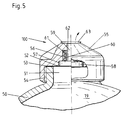
- the embodiment according to FIG. 5 has an opening 51 on the compressed air bottle 50 which is provided with a metal foil 52 which is firmly connected to the peripheral edge 53 of the threaded opening 51.
- a closure cap 55 is screwed onto the thread 54 of the thread opening 51.
- This cap 55 has in the center a two-stage through hole 56 which becomes narrower from the inside to the outside.
- a cylindrical element 58 is supported, which rests on the metal foil 52.
- This cylindrical element 58 has a second cylindrical element 59 in the center, which has the same diameter as the narrowest part of the through-hole 56.
- the metal foil 52 In the central part 60 of the through-hole 56 there is a spiral spring 61 which surrounds the second cylindrical element 59 and is located on the cylindrical element 58 and the cap 55 supports.
- the metal foil 52 In the filled state, the metal foil 52 is flat, so that the second cylindrical element 59 is flush with the closure cap 55.
- an indicator plate 63 On the circular surface 62 of the second element 59, which is visible cylindrically in the through hole 56, an indicator plate 63 is glued, which has a larger diameter than the through hole 56.
- the metal foil 52 In the unfilled state of the compressed air bottle 50, the metal foil 52 is curved inwards so that the cylindrical elements 58 and 59 have moved in the direction of the compressed air bottle 50, under the influence of the spiral spring 61, and the indicator plate 63 has been torn off.
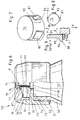
- the right side of FIG. 6 shows the unfilled state and the left side the filled state.
- the compressed air bottle 50 has an opening 51 which is firmly closed with a metal foil 52 which is firmly connected to the rim 53 of the bottle neck-like opening 51 which runs around the top.
- a closure cap 55 is screwed onto the external thread 54 of the bottle-neck-like opening 51.
- the metal foil is arranged so that there is no connection of the pressure space to the outside via the opening 51, since the metal foil forms the flexible part of the wall of the compressed air bottle 50.
- the closure cap 55 has a cover surface 65 which overlaps the opening 51 and thus the metal foil 52 and in the center of which a through bore 66 is formed which becomes narrower in two stages from the inside to the outside.
- a first cylindrical element 68 is held, which rests firmly on the metal foil 52.
- the metal foil is completely covered and supported by the first cylindrical element 68 and the cover surface 65.
- the first cylindrical element 68 carries a second cylindrical element 69 in the center. This second cylindrical element 69 has a smaller diameter than the narrower step 70 of the through bore 66 in the cover surface 65.
- a spiral spring 71 is arranged around the second cylindrical element 69.
- the lateral wall 72 of the closure cap 55 is formed so as to project beyond the cover surface and encloses a cylindrical interior space 73 open at the top.
- a closure plate 74 placed on top of the peripheral edge of the side wall 72, which is firmly connected to the side wall 72 by being screwed to the side wall 72 with a downwardly projecting section 75.
- An indicator element 76 is arranged in the interior 73 and is cylindrical in shape.
- a two-stage narrowing through opening 77 is formed in the closure plate 74, the outside diameter of the indicator element 76 corresponding to the inside diameter of the narrower part 78 of the through opening 77, while the lower second part 79 of the through hole has a larger inside diameter.
- the indicator element 76 is designed as a pot-like hollow body and has four locking elements 80, 81, 82, 83 arranged in the side wall. These are separated from the side wall 74 of the indicator element by incisions running in the longitudinal direction of the indicator element such that they are only connected to the indicator element via a connecting line 85 and are therefore arranged elastically on the latter. Each locking element has an extension at its free end, which carries a contact surface 86 on the outside.
- the transition between the first step 78 and the second step 79 of the through hole 77 in the closure plate 74 is designed as an inclined surface 87, which corresponds in its shape to the contact surface 86 of each locking element 80, 81, 82, 83.
- the lower edge 78 of the indicator element 76 is supported on the spiral spring 71, which in turn is supported on the first cylindrical element 68.
- the coil spring 71 therefore presses against the indicator element from below 76, which would pass through the through hole 77 in the closure plate 74, if the contact surfaces 86 of the locking elements 80, 81, 82, 83 were not in contact with the inclined surface 87 in the closure plate 74 and thus the indicator element 76 were retained.
- the locking elements 80, 81, 82, 83 are prevented from pivoting inwards and releasing the indicator element 76, since the indicator element 76 is hollow-cylindrical and the second cylindrical element 69 is inserted into the indicator element like a piston.
- the second cylindrical element 69 In the position in which the second cylindrical element 69 is when the compressed air bottle 50 is properly filled, the second cylindrical element 69 is inserted into the indicator element 76 to such an extent that the locking elements 80, 81, 82, 83 are blocked against pivoting inward. These can then not pivot out of their blocking position and with the contact surface 86, the support section formed by the inclined surface 87 in the locking plate 74, so that the indicator element 76 is held firmly in the locking plate 74.
- the second cylindrical element 68 moves out of the indicator element 76 in the direction designated X in the drawing .
- the locking elements 80, 81, 82, 83 can move inward in the Y direction into the interior of the indicator element 76 and the indicator element 76 is no longer held in the closure plate 74.
- the indicator element 76 is pushed through the through opening 77 in the closure plate 74.
- the indicator element either protrudes or it is completely ejected. In any case, it is immediately apparent from the outside that the pressure has fallen below a certain predetermined limit.
Landscapes
- Engineering & Computer Science (AREA)
- Mechanical Engineering (AREA)
- General Engineering & Computer Science (AREA)
- Health & Medical Sciences (AREA)
- Public Health (AREA)
- Business, Economics & Management (AREA)
- Emergency Management (AREA)
- Physics & Mathematics (AREA)
- General Physics & Mathematics (AREA)
- Closures For Containers (AREA)
- Compressor (AREA)
- Air-Conditioning For Vehicles (AREA)
- Cooling, Air Intake And Gas Exhaust, And Fuel Tank Arrangements In Propulsion Units (AREA)
- Filling Or Discharging Of Gas Storage Vessels (AREA)
- Measuring Fluid Pressure (AREA)
Applications Claiming Priority (2)
| Application Number | Priority Date | Filing Date | Title |
|---|---|---|---|
| DE9303295U | 1993-03-06 | ||
| DE9303295U DE9303295U1 (de) | 1993-03-06 | 1993-03-06 | Indikator für Druckluftflaschen |
Publications (2)
| Publication Number | Publication Date |
|---|---|
| EP0615093A1 true EP0615093A1 (fr) | 1994-09-14 |
| EP0615093B1 EP0615093B1 (fr) | 1997-09-17 |
Family
ID=6890284
Family Applications (1)
| Application Number | Title | Priority Date | Filing Date |
|---|---|---|---|
| EP94102633A Expired - Lifetime EP0615093B1 (fr) | 1993-03-06 | 1994-02-22 | Indicateur pour une bouteille d'air sous pression |
Country Status (4)
| Country | Link |
|---|---|
| US (1) | US5493900A (fr) |
| EP (1) | EP0615093B1 (fr) |
| AT (1) | ATE158393T1 (fr) |
| DE (2) | DE9303295U1 (fr) |
Cited By (2)
| Publication number | Priority date | Publication date | Assignee | Title |
|---|---|---|---|---|
| DE19731991A1 (de) * | 1997-07-05 | 1997-12-18 | Wolfgang Merkel | Füllstandanzeiger für Gasflaschen |
| US6589087B2 (en) | 2001-09-07 | 2003-07-08 | Halkey-Roberts Corporation | Automatic inflator with status indicator |
Families Citing this family (2)
| Publication number | Priority date | Publication date | Assignee | Title |
|---|---|---|---|---|
| FR2796125B1 (fr) * | 1999-07-09 | 2001-08-10 | Liotard Metallurg | Reservoir resistant a l'eclatement dont une cloison se rompt au-dela d'une certaine pression |
| CN2544359Y (zh) * | 2002-06-07 | 2003-04-09 | 宋有洲 | 室内防暴捕捉器 |
Citations (5)
| Publication number | Priority date | Publication date | Assignee | Title |
|---|---|---|---|---|
| FR1258750A (fr) * | 1959-06-09 | 1961-04-14 | Pyrene Co Ltd | Perfectionnement apporté aux récipients sous pression |
| US4023415A (en) * | 1974-04-18 | 1977-05-17 | G. E. Garcia | Pressure monitoring device |
| FR2429601A1 (fr) * | 1978-06-30 | 1980-01-25 | Procedes Modernes Impression | Dispositif de securite pour extincteur d'incendie |
| FR2555290A1 (fr) * | 1983-11-21 | 1985-05-24 | Clesse Mandet Sa | Dispositif de visualisation de l'etat de charge d'un poste d'alimentation en gaz |
| US5027740A (en) * | 1990-01-19 | 1991-07-02 | Robert Kramer | Valve cap pressure drop indicator |
Family Cites Families (8)
| Publication number | Priority date | Publication date | Assignee | Title |
|---|---|---|---|---|
| DE216532C (fr) * | ||||
| DE205996C (fr) * | ||||
| US3950983A (en) * | 1973-07-05 | 1976-04-20 | Treadwell Corporation | Air leak detector |
| DE3035766C2 (de) * | 1980-09-23 | 1985-08-14 | Vtg Vereinigte Tanklager Und Transportmittel Gmbh, 2000 Hamburg | Warneinrichtung zur Anzeige einer Druckerhöhung in einem Behälter |
| US4528840A (en) * | 1984-02-06 | 1985-07-16 | Wass Lloyd G | Hydrostatic test stand |
| NO155717C (no) * | 1984-07-13 | 1987-05-13 | Moss Glasvaerk As | Innretning for pneumatisk kontroll av beholdere med hensyn til tetthet og sperrende defekter. |
| GB2164453B (en) * | 1984-09-10 | 1989-05-24 | Trace Societe De Traitement Au | Apparatus for leak testing at least one wall portion and/or a volume delimited by said wall portion |
| US5105653A (en) * | 1991-02-15 | 1992-04-21 | Konter Richard J | Pressure testing device for vehicle radiators and cooling systems |
-
1993
- 1993-03-06 DE DE9303295U patent/DE9303295U1/de not_active Expired - Lifetime
-
1994
- 1994-02-03 US US08/191,859 patent/US5493900A/en not_active Expired - Lifetime
- 1994-02-22 EP EP94102633A patent/EP0615093B1/fr not_active Expired - Lifetime
- 1994-02-22 AT AT94102633T patent/ATE158393T1/de not_active IP Right Cessation
- 1994-02-22 DE DE59404060T patent/DE59404060D1/de not_active Expired - Fee Related
Patent Citations (5)
| Publication number | Priority date | Publication date | Assignee | Title |
|---|---|---|---|---|
| FR1258750A (fr) * | 1959-06-09 | 1961-04-14 | Pyrene Co Ltd | Perfectionnement apporté aux récipients sous pression |
| US4023415A (en) * | 1974-04-18 | 1977-05-17 | G. E. Garcia | Pressure monitoring device |
| FR2429601A1 (fr) * | 1978-06-30 | 1980-01-25 | Procedes Modernes Impression | Dispositif de securite pour extincteur d'incendie |
| FR2555290A1 (fr) * | 1983-11-21 | 1985-05-24 | Clesse Mandet Sa | Dispositif de visualisation de l'etat de charge d'un poste d'alimentation en gaz |
| US5027740A (en) * | 1990-01-19 | 1991-07-02 | Robert Kramer | Valve cap pressure drop indicator |
Cited By (2)
| Publication number | Priority date | Publication date | Assignee | Title |
|---|---|---|---|---|
| DE19731991A1 (de) * | 1997-07-05 | 1997-12-18 | Wolfgang Merkel | Füllstandanzeiger für Gasflaschen |
| US6589087B2 (en) | 2001-09-07 | 2003-07-08 | Halkey-Roberts Corporation | Automatic inflator with status indicator |
Also Published As
| Publication number | Publication date |
|---|---|
| DE9303295U1 (de) | 1994-07-07 |
| ATE158393T1 (de) | 1997-10-15 |
| US5493900A (en) | 1996-02-27 |
| EP0615093B1 (fr) | 1997-09-17 |
| DE59404060D1 (de) | 1997-10-23 |
Similar Documents
| Publication | Publication Date | Title |
|---|---|---|
| AT409121B (de) | Aufblasvorrichtung, insbesondere für eine rettungsweste | |
| DE7517471U (de) | Vorrichtung zum betaetigen eines steuerorgans bei wahrnehmung einer erschuetterung | |
| DE3104081A1 (de) | "druckpruefgeraet fuer druckluftreifen" | |
| DE69421510T2 (de) | Ventilanordnung | |
| DE69621956T2 (de) | Ventilkappe mit reifendruckanzeige | |
| DE4111862A1 (de) | Druckmessgeraet | |
| EP1423671A1 (fr) | Dispositif d'indication de pression | |
| DE3030794A1 (de) | Luftverlust-warnvorrichtung fuer einen luftreifen | |
| EP0583746A1 (fr) | Dispositif d'indication pour un appareil de gonflage, notamment pour un conteneur ou un flotteur d'un ensemble de sauvetage | |
| EP1109684B1 (fr) | Dispositif d'amortissement pneumatique a fermeture automatique | |
| EP0535299A1 (fr) | Dispositif de gonflage, notamment pour un récipient ou un flotteur d'un appareil de sauvetage | |
| EP0615093A1 (fr) | Indicateur pour une bouteille d'air sous pression | |
| DE2810996A1 (de) | Abgabeventil fuer aufgeschlagene sahne | |
| EP0038978B1 (fr) | Dispositif de réglage de pression avec indicateur pour au moins deux récipients sous pression interconnectés | |
| DE202004000564U1 (de) | Elektronisches Manometer | |
| DE2219097A1 (de) | Druckanzeiger für Luftreifen | |
| EP0532945B1 (fr) | Réservoir sous pression | |
| EP0004595A2 (fr) | Soupape réglable pour installation d'extinction du feu | |
| DE1475786C3 (de) | Hydropneumatic her Druckspeicher | |
| EP0909917A2 (fr) | Système de stockage de gaz | |
| DE2324170A1 (de) | Behaelterverschluss mit druckausgleichventil, insbesondere fuer kraftfahrzeugkraftstoffbehaelter | |
| DE2122023C3 (de) | Füllvorrichtung für aufblasbare Insassen-Rückhaltesysteme in Kraftfahrzeugen | |
| DE29821537U1 (de) | Luftventil | |
| DE2448698A1 (de) | Reifen- bzw. schlauchventil | |
| EP3805627A1 (fr) | Dispositif de protection pour récipient à gaz comprimé |
Legal Events
| Date | Code | Title | Description |
|---|---|---|---|
| PUAI | Public reference made under article 153(3) epc to a published international application that has entered the european phase |
Free format text: ORIGINAL CODE: 0009012 |
|
| AK | Designated contracting states |
Kind code of ref document: A1 Designated state(s): AT BE CH DE DK FR GB IT LI NL SE |
|
| 17P | Request for examination filed |
Effective date: 19940725 |
|
| 17Q | First examination report despatched |
Effective date: 19950502 |
|
| GRAG | Despatch of communication of intention to grant |
Free format text: ORIGINAL CODE: EPIDOS AGRA |
|
| GRAH | Despatch of communication of intention to grant a patent |
Free format text: ORIGINAL CODE: EPIDOS IGRA |
|
| GRAH | Despatch of communication of intention to grant a patent |
Free format text: ORIGINAL CODE: EPIDOS IGRA |
|
| GRAA | (expected) grant |
Free format text: ORIGINAL CODE: 0009210 |
|
| AK | Designated contracting states |
Kind code of ref document: B1 Designated state(s): AT BE CH DE DK FR GB IT LI NL SE |
|
| PG25 | Lapsed in a contracting state [announced via postgrant information from national office to epo] |
Ref country code: NL Free format text: LAPSE BECAUSE OF FAILURE TO SUBMIT A TRANSLATION OF THE DESCRIPTION OR TO PAY THE FEE WITHIN THE PRESCRIBED TIME-LIMIT Effective date: 19970917 Ref country code: IT Free format text: LAPSE BECAUSE OF FAILURE TO SUBMIT A TRANSLATION OF THE DESCRIPTION OR TO PAY THE FEE WITHIN THE PRESCRIBED TIME-LIMIT;WARNING: LAPSES OF ITALIAN PATENTS WITH EFFECTIVE DATE BEFORE 2007 MAY HAVE OCCURRED AT ANY TIME BEFORE 2007. THE CORRECT EFFECTIVE DATE MAY BE DIFFERENT FROM THE ONE RECORDED. Effective date: 19970917 Ref country code: FR Free format text: LAPSE BECAUSE OF FAILURE TO SUBMIT A TRANSLATION OF THE DESCRIPTION OR TO PAY THE FEE WITHIN THE PRESCRIBED TIME-LIMIT Effective date: 19970917 Ref country code: DK Free format text: LAPSE BECAUSE OF NON-PAYMENT OF DUE FEES Effective date: 19970917 |
|
| REF | Corresponds to: |
Ref document number: 158393 Country of ref document: AT Date of ref document: 19971015 Kind code of ref document: T |
|
| REG | Reference to a national code |
Ref country code: CH Ref legal event code: EP |
|
| GBT | Gb: translation of ep patent filed (gb section 77(6)(a)/1977) |
Effective date: 19970919 |
|
| REF | Corresponds to: |
Ref document number: 59404060 Country of ref document: DE Date of ref document: 19971023 |
|
| PG25 | Lapsed in a contracting state [announced via postgrant information from national office to epo] |
Ref country code: SE Effective date: 19971217 |
|
| EN | Fr: translation not filed | ||
| PG25 | Lapsed in a contracting state [announced via postgrant information from national office to epo] |
Ref country code: LI Free format text: LAPSE BECAUSE OF NON-PAYMENT OF DUE FEES Effective date: 19980228 Ref country code: CH Free format text: LAPSE BECAUSE OF NON-PAYMENT OF DUE FEES Effective date: 19980228 Ref country code: BE Free format text: LAPSE BECAUSE OF NON-PAYMENT OF DUE FEES Effective date: 19980228 |
|
| NLV1 | Nl: lapsed or annulled due to failure to fulfill the requirements of art. 29p and 29m of the patents act | ||
| PLBE | No opposition filed within time limit |
Free format text: ORIGINAL CODE: 0009261 |
|
| STAA | Information on the status of an ep patent application or granted ep patent |
Free format text: STATUS: NO OPPOSITION FILED WITHIN TIME LIMIT |
|
| BERE | Be: lapsed |
Owner name: BERNHARDT APPARATEBAU G.M.B.H. U. CO. Effective date: 19980228 |
|
| 26N | No opposition filed | ||
| REG | Reference to a national code |
Ref country code: CH Ref legal event code: PL |
|
| REG | Reference to a national code |
Ref country code: GB Ref legal event code: IF02 |
|
| PGFP | Annual fee paid to national office [announced via postgrant information from national office to epo] |
Ref country code: GB Payment date: 20050211 Year of fee payment: 12 |
|
| PGFP | Annual fee paid to national office [announced via postgrant information from national office to epo] |
Ref country code: AT Payment date: 20050218 Year of fee payment: 12 |
|
| PGFP | Annual fee paid to national office [announced via postgrant information from national office to epo] |
Ref country code: DE Payment date: 20050421 Year of fee payment: 12 |
|
| PG25 | Lapsed in a contracting state [announced via postgrant information from national office to epo] |
Ref country code: GB Free format text: LAPSE BECAUSE OF NON-PAYMENT OF DUE FEES Effective date: 20060222 Ref country code: AT Free format text: LAPSE BECAUSE OF NON-PAYMENT OF DUE FEES Effective date: 20060222 |
|
| PG25 | Lapsed in a contracting state [announced via postgrant information from national office to epo] |
Ref country code: DE Free format text: LAPSE BECAUSE OF NON-PAYMENT OF DUE FEES Effective date: 20060901 |
|
| GBPC | Gb: european patent ceased through non-payment of renewal fee |
Effective date: 20060222 |