EP0615111A1 - Signalgeber - Google Patents
Signalgeber Download PDFInfo
- Publication number
- EP0615111A1 EP0615111A1 EP93104058A EP93104058A EP0615111A1 EP 0615111 A1 EP0615111 A1 EP 0615111A1 EP 93104058 A EP93104058 A EP 93104058A EP 93104058 A EP93104058 A EP 93104058A EP 0615111 A1 EP0615111 A1 EP 0615111A1
- Authority
- EP
- European Patent Office
- Prior art keywords
- signal
- threshold value
- transferred
- evaluation circuit
- transmitter
- Prior art date
- Legal status (The legal status is an assumption and is not a legal conclusion. Google has not performed a legal analysis and makes no representation as to the accuracy of the status listed.)
- Granted
Links
Images
Classifications
-
- F—MECHANICAL ENGINEERING; LIGHTING; HEATING; WEAPONS; BLASTING
- F02—COMBUSTION ENGINES; HOT-GAS OR COMBUSTION-PRODUCT ENGINE PLANTS
- F02P—IGNITION, OTHER THAN COMPRESSION IGNITION, FOR INTERNAL-COMBUSTION ENGINES; TESTING OF IGNITION TIMING IN COMPRESSION-IGNITION ENGINES
- F02P7/00—Arrangements of distributors, circuit-makers or -breakers, e.g. of distributor and circuit-breaker combinations or pick-up devices
- F02P7/06—Arrangements of distributors, circuit-makers or -breakers, e.g. of distributor and circuit-breaker combinations or pick-up devices of circuit-makers or -breakers, or pick-up devices adapted to sense particular points of the timing cycle
- F02P7/067—Electromagnetic pick-up devices, e.g. providing induced current in a coil
- F02P7/07—Hall-effect pick-up devices
-
- G—PHYSICS
- G01—MEASURING; TESTING
- G01D—MEASURING NOT SPECIALLY ADAPTED FOR A SPECIFIC VARIABLE; ARRANGEMENTS FOR MEASURING TWO OR MORE VARIABLES NOT COVERED IN A SINGLE OTHER SUBCLASS; TARIFF METERING APPARATUS; MEASURING OR TESTING NOT OTHERWISE PROVIDED FOR
- G01D3/00—Indicating or recording apparatus with provision for the special purposes referred to in the subgroups
- G01D3/02—Indicating or recording apparatus with provision for the special purposes referred to in the subgroups with provision for altering or correcting the law of variation
- G01D3/022—Indicating or recording apparatus with provision for the special purposes referred to in the subgroups with provision for altering or correcting the law of variation having an ideal characteristic, map or correction data stored in a digital memory
-
- G—PHYSICS
- G01—MEASURING; TESTING
- G01D—MEASURING NOT SPECIALLY ADAPTED FOR A SPECIFIC VARIABLE; ARRANGEMENTS FOR MEASURING TWO OR MORE VARIABLES NOT COVERED IN A SINGLE OTHER SUBCLASS; TARIFF METERING APPARATUS; MEASURING OR TESTING NOT OTHERWISE PROVIDED FOR
- G01D3/00—Indicating or recording apparatus with provision for the special purposes referred to in the subgroups
- G01D3/08—Indicating or recording apparatus with provision for the special purposes referred to in the subgroups with provision for safeguarding the apparatus, e.g. against abnormal operation, against breakdown
Definitions
- the invention relates to a signal generator according to claim 1 (EP 0 024 836 B1).
- Known signal transmitters of the type mentioned scan teeth or segments and gaps of a rotating transmitter part, which initially creates an analog electrical image of the surface of the transmitter part. This analog sensor signal is then converted into a series of discrete, digital status messages (tooth, gap, reference tooth or reference gap). At least one decision threshold is required for this conversion. Two thresholds are also common, which are distinguished from one another, for example, by a hysteresis amount.
- a signal transmitter is known from EP 0 024 836 B1, in which the analog sensor signal is compared with a threshold value which corresponds to the mean value formed from the smallest and largest signal value (the positive and negative peak value) of the sensor signal.
- DE 37 14 271 A1 discloses an inductive signal transmitter with an evaluation circuit which compares the sensor signal with two threshold values which are formed by a comparator which has a switching hysteresis.
- the signal generators mentioned can only be used in dynamic operation, since they require a certain speed or a certain number of revolutions for the formation of evaluable threshold values, that is to say they only emit a usable digital sensor signal after a few revolutions or from a minimum speed.
- the object of the invention is to design such signal transmitters in such a way that they emit a usable sensor signal even at the start of operation in static operation (in motor vehicle internal combustion engines: when the engine is at a standstill with the supply voltage applied to the signal transmitter).
- This object is achieved in that a non-volatile memory is provided, in which the at least one threshold value can be transferred and can be transferred back to the evaluation circuit when the operation starts again.
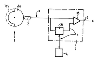
- This exemplary embodiment describes a camshaft sensor for a motor vehicle internal combustion engine.
- a transmitter part 1 is fixedly connected, which rotates with the camshaft about its own axis when the internal combustion engine is running.
- This transmitter part has a segment 1a and a segment gap 1b, both of which each extend over half the circumference of the transmitter part.
- a stationary sensor 2 is arranged opposite the transmitter part 1, which is designed, for example, as an angular pulse transmitter with evaluation of the phase shift between the excitation signal and the response signal, as described, for example, in DE-A-25 32 226.
- this transducer delivers an analog signal s with corresponding continuous transitions from the start of operation (switched on supply voltage and standstill of the internal combustion engine) through motor operation (working internal combustion engine) to the end of operation (switching off the supply voltage).
- This signal is fed to an evaluation circuit 3, which has a device 3a for forming a threshold value r from the sensor signal s, which for example corresponds to the mean value from the extreme values of the sensor signal s.
- the sensor signal s is compared in a comparator 3b, at the output of which a digital transmitter signal g appears, for example a HIGH signal when the sensor is facing the segment 1a, or a LOW signal when the transducer faces the segment gap.
- the threshold value is always set so that the segment and gap are reliably recognized as such.
- a non-volatile memory 4 is connected to the evaluation circuit 3 or to the device 3a for forming the threshold value r, into which the determined threshold value is transferred after each determination, or at least at the end of operation, and is transferred back to the device 3a at the start of operation.
- Non-volatile means that the stored value is retained even if the supply voltage is switched off.
- a transmission of the threshold value after each determination has the advantage that the end of the operation does not have to be saved, but the supply voltage can be switched off immediately without further measures .
- a threshold value r is immediately available at the start of operation (after the supply voltage is switched on again), with which the sensor signal s can be compared, and a statement can be made as to whether the sensor is currently facing a segment or a gap, even before the engine is started. If a sufficiently fast microprocessor is available, the evaluation circuit 3 (with threshold value formation device 3a and comparator 3b) and the memory 4 can be integrated in it, so that only the sensor 2 is provided as an "external" component, which is directly connected to the Microprocessor is connected. In this case, a program for a known optimization or readjustment of the threshold value depending on the curve shape of the sensor signal can also be provided.
- the last pair of threshold values determined is stored in a non-volatile manner and transferred to the evaluation circuit again when the next start of operation.
Landscapes
- Engineering & Computer Science (AREA)
- Physics & Mathematics (AREA)
- General Physics & Mathematics (AREA)
- Technology Law (AREA)
- Electromagnetism (AREA)
- Chemical & Material Sciences (AREA)
- Combustion & Propulsion (AREA)
- Mechanical Engineering (AREA)
- General Engineering & Computer Science (AREA)
- Combined Controls Of Internal Combustion Engines (AREA)
- Testing Of Engines (AREA)
Abstract
Description
- Die Erfindung betrifft einen Signalgeber nach Anspruch 1 (EP 0 024 836 B1).
- Bekannte Signalgeber der genannten Art tasten Zähne bzw. Segmente und Lücken eines drehenden Geberteils ab, wodurch zunächst ein analoges elektrisches Abbild der Oberfläche des Geberteils entsteht. Anschließend wird dieses analoge Sensorsignal in eine Folge diskreter, digitaler Zustandsmeldungen (Zahn, Lücke, Referenzzahn bzw. Referenzlücke) umgewandelt. Für diese Umwandlung wird mindestens eine Entscheidungsschwelle benötigt. Üblich sind auch zwei Schwellen, die beispielsweise durch einen Hysteresebetrag voneinander unterschieden sind.
- Aus der EP 0 024 836 B1 ist ein Signalgeber bekannt, bei welchem das analaoge Sensorsignal mit einem Schwellwert verglichen wird, der dem aus dem kleinsten und größten Signalwert (dem positiven und negativen Spitzenwert) des Sensorsignals gebildeten Mittelwert entspricht.
- Aus der DE 37 14 271 A1 ist ein induktiver Signalgeber mit einer Auswerteschaltung bekannt, die das Sensorsignal mit zwei Schwellwerten vergleicht, welche durch einen Komparator, der eine Schalthysterese aufweist, gebildet werden.
- In der nicht vorveröffentlichten europäischen Patentanmeldung 92116742.5 ist ein Signalgeber beschrieben, bei dem das Sensorsignal mit zwei Schwellwerten verglichen wird, die durch Addition eines bestimmten Betrages zum unteren Spitzenwert des Sensorsignals bzw. durch Subtraktion vom oberen Spitzenwert gebildet werden.
- Die genannten Signalgeber sind nur im dynamischen Betriebsfall verwendbar, da sie eine bestimmte Drehzahl bzw. eine bestimmte Zahl von Umdrehungen für die Bildung auswertbarer Schwellwerte benötigen, also erst nach einigen Umdrehungen bzw. ab einer Mindestdrehzahl ein verwertbares digitales Gabersignal abgeben.
- Bei Motorsteuerungen in Kraftfahrzeugen ist es sehr wichtig, so früh wie möglich, am besten bereits bei Betriebsbeginn (bei eingeschalteter Versorgungsspannung und vor dem Anlassen der Brennkraftmaschine), zu wissen, in welchem Zyklus (in welcher Stellung) sich der Motor befindet, um bestimmen zu können, welcher Zylinder als erster oder nächster mit Kraftstoff versorgt bzw. gezündet werden soll.
- Aufgabe der Erfindung ist es, derartige Signalgeber so auszubilden, daß sie auch bei Betriebsbeginn im statischen Betriebsfall (bei Kfz-Brennkraftmaschinen: bei Motorstillstand mit an dem Signalgeber liegender Versorgungsspannung), ein verwertbares Gebersignal abgeben.
- Diese Aufgabe wird dadurch gelöst, daß ein nichtflüchtiger Speicher vorgesehen ist, in welchen der wenigstens eine Schwellwert übertragbar und bei erneutem Betriebsbeginn in die Auswerteschaltung rückübertragbar ist.
- Damit wird erreicht, daß bei Betriebsbeginn, also bereits beim Einschalten der Versorgungsspannung (Zündung) und vor dem Anlassen des Motors, der wenigstens eine Schwellwert vorliegt, mit welchem das ebenfalls statisch bereits vorliegende Sensorsignal verglichen werden kann.
- Ein Ausführungsbeispiel der Erfindung ist im folgenden unter Bezugnahme auf die schematische Zeichnung näher erläutert.
- Dieses Ausführungsbeispiel beschreibt einen Nockenwellengeber für eine Kraftfahrzeug-Brennkraftmaschine.
- Mit der nicht dargestellten Nockenwelle ist ein Geberteil 1 fest verbunden, welches sich bei laufender Brennkraftmaschine mit der Nockenwelle um die eigene Achse dreht. Dieses Geberteil weist ein Segment 1a und eine Segmentlücke 1b auf, die sich beide jeweils über den halben Umfang des Geberteils erstrecken.
- Dem Geberteil 1 gegenüber ist ein ortsfester Aufnehmer 2 angeordnet, der beispielsweise als Winkelimpulsgeber mit Auswertung der Phasenverschiebung zwischen Anregungssignal und Antwortsignal, wie beispielsweise in der DE-A-25 32 226 beschrieben, ausgebildet ist.
- Dieser Aufnehmer liefert an seinem Ausgang von Betriebsbeginn (eingeschaltete Versorgungsspannung und Stillstand der Brennkraftmaschine) über Motorbetrieb (arbeitende Brennkraftmaschine) bis Betriebsende (Abschalten der Versorgungsspannung) ein analoges Signal s mit entsprechenden stetigen Übergängen. Dieses Signal wird einer Auswerteschaltung 3 zugeführt, die eine Einrichtung 3a zur Bildung eines Schwellwertes r aus dem Sensorsignal s aufweist, der beispielsweise dem Mittelwert aus den Extremwerten des Sensorsignals s entspricht.
Mit diesem Schwellwert r wird das Sensorsignal s in einem Komparator 3b verglichen, an dessen Ausgang ein digitales Gebersignal g erscheint, beispielsweise ein HIGH-Signal, wenn dem Aufnehmer das Segment 1a gegenübersteht, oder ein LOW-Signal, wenn dem Aufnehmer die Segmentlücke gegenübersteht. - Unabhängig vom Abstand des Geberteils 1 vom Aufnehmer 2, von welchem die Amplituden (die Extremwerte) des Sensorsignals s bestimmt werden, wird der Schwellwert immer so gelegt, daß Segment und Lücke als solche sicher erkannt werden.
- Mit der Auswerteschaltung 3 bzw. mit der Einrichtung 3a zur Bildung des Schwellwertes r ist ein nichtflüchtiger Speicher 4 verbunden, in den der ermittelte Schwellwert nach jeder Ermittlung, zumindest aber bei Betriebsende übertragen und bei Betriebsbeginn wieder in die Einrichtung 3a zurückubertragen wird. (Nichtflüchtig bedeutet, daß der gespeicherte Wert auch dann erhalten bleibt, wenn die Versorgungsspannung abgeschaltet wird.) Eine Übertragung des Schwellwertes nach jeder Ermittlung hat den Vorteil, daß bei Betriebsende nicht erst abgespeichert werden muß, sondern die Versorgungsspannung sofort ohne weitere Maßnahmen abgeschaltet werden kann.
- Dadurch ergibt sich der Vorteil, daß bei Bestriebsbeginn (nach Wiedereinschalten der Versorgungsspannung) sofort ein Schwellwert r zur Verfügung steht, mit welchem das Sensorsignal s verglichen werden kann, und eine Aussage gemacht werden kann, ob dem Aufnehmer gerade ein Segment oder eine Lücke gegenübersteht, noch bevor die Brennkraftmaschine angelassen wird.
Steht ein ausreichend schneller Mikroprozessor zur Verfügung, so können die Auswerteschaltung 3 (mit Schwellwertbildungseinrichtung 3a und Komparator 3b) und der Speicher 4 in diesem integriert sein, so daß als "externes" Bauele ment nur der Aufnehmer 2 vorgesehen ist, der direkt an den Mikroprozessor angeschlossen ist. In diesem Fall kann auch ein Programm für eine an sich bekannte Optimierung bzw. Nachregelung des Schwellwertes in Abhängigkeit von der Kurvenform des Sensorsignals vorgesehen werden. - Wird eine Sensorsignal-Auswertung mit zwei Schwellwerten vorgenommen, so wird jeweils das zuletzt ermittelte Schwellwertpaar nichtflüchtig abgespeichert und beim nächsten Betriebsbeginn wieder in die Auswerteschaltung übertragen.
Claims (5)
- Signalgeber, insbesondere Kurbel- oder Nockenwellensegmentgeber für Brennkraftmaschinen,- mit einem mit wenigstens einem Zahn bzw. Segment (1a) und wenigstens einer Zahn- bzw. Segmentlücke (1b) versehenen, drehbaren Geberteil (1),- mit einem ortsfesten Aufnehmer (2), welcher ein den ihm gegenüberstehenden Zähnen bzw. Segmenten (1a) oder Lücken (1b) des Geberteils (1) zugeordnetes Sensorsignal (s) erzeugt,- mit einer Auswerteschaltung (3), in welcher das Sensorsignal (s) durch Vergleich mit wenigstens einem Schwellwert (r) in ein digitales Gebersignal (g) umgewandelt wird, und- mit einem nichtflüchtigen Speicher (4), in welchen der wenigstens eine Schwellwert (r) übertragbar und bei erneutem Betriebsbeginn in die Auswerteschaltung (3) rückübertragbar ist.
- Signalgeber nach Anspruch 1,
dadurch gekennzeichnet, daß der Schwellwert (r) in periodischen Abständen ermittelt wird. - Signalgeber nach Anspruch 1,
dadurch gekennzeichnet, daß der Schwellwert (r) nach jeder Ermittlung in den Speicher (4) übertragen wird. - Signalgeber nach Anspruch 1,
dadurch gekennzeichnet, daß der Schwellwert 4 (r) bei Betriebsende in den Speicher (4) übertragen wird. - Signalgeber nach Anspruch 1,
dadurch gekennzeichnet, daß Auswerteschaltung (3) und nichtflüchtiger Speicher (4) in einem Mikroprozessor enthalten sind.
Priority Applications (3)
| Application Number | Priority Date | Filing Date | Title |
|---|---|---|---|
| EP19930104058 EP0615111B2 (de) | 1993-03-12 | 1993-03-12 | Kurbel- oder Nockenwellensignalgeber |
| DE59304127T DE59304127D1 (de) | 1993-03-12 | 1993-03-12 | Signalgeber |
| ES93104058T ES2092709T5 (es) | 1993-03-12 | 1993-03-12 | Transmisor de señales de un cigueñal o de un arbol de levas. |
Applications Claiming Priority (1)
| Application Number | Priority Date | Filing Date | Title |
|---|---|---|---|
| EP19930104058 EP0615111B2 (de) | 1993-03-12 | 1993-03-12 | Kurbel- oder Nockenwellensignalgeber |
Publications (3)
| Publication Number | Publication Date |
|---|---|
| EP0615111A1 true EP0615111A1 (de) | 1994-09-14 |
| EP0615111B1 EP0615111B1 (de) | 1996-10-09 |
| EP0615111B2 EP0615111B2 (de) | 1999-12-29 |
Family
ID=8212692
Family Applications (1)
| Application Number | Title | Priority Date | Filing Date |
|---|---|---|---|
| EP19930104058 Expired - Lifetime EP0615111B2 (de) | 1993-03-12 | 1993-03-12 | Kurbel- oder Nockenwellensignalgeber |
Country Status (3)
| Country | Link |
|---|---|
| EP (1) | EP0615111B2 (de) |
| DE (1) | DE59304127D1 (de) |
| ES (1) | ES2092709T5 (de) |
Cited By (4)
| Publication number | Priority date | Publication date | Assignee | Title |
|---|---|---|---|---|
| DE19936763A1 (de) * | 1999-08-09 | 2001-02-15 | Mannesmann Vdo Ag | Selbstadaptiver Sensor |
| US6281653B1 (en) | 1997-01-28 | 2001-08-28 | Robert Bosch Gmbh | Method of detecting after-running of electrical servomotors provided with means for incremental position detection |
| DE10252031A1 (de) * | 2002-11-06 | 2004-05-27 | Micronas Gmbh | Vorrichtung und Verfahren zum Erfassen einer Winkelposition eines rotierenden Gegenstandes |
| WO2004070319A1 (de) * | 2003-02-07 | 2004-08-19 | Robert Bosch Gmbh | Verfahren zur diagnose eines sensors |
Families Citing this family (1)
| Publication number | Priority date | Publication date | Assignee | Title |
|---|---|---|---|---|
| US7373928B2 (en) | 2006-05-31 | 2008-05-20 | Joseph Thomas | Method for starting a direct injection engine |
Citations (5)
| Publication number | Priority date | Publication date | Assignee | Title |
|---|---|---|---|---|
| EP0024836A1 (de) * | 1979-08-08 | 1981-03-11 | Ford Motor Company Limited | Signalzustands-Detektorschaltung |
| GB2125565A (en) * | 1982-08-12 | 1984-03-07 | Honda Motor Co Ltd | Detecting abnormality in an internal combustion engine air intake parameter sensor |
| WO1986003831A1 (fr) * | 1984-12-19 | 1986-07-03 | Robert Bosch Gmbh | Sonde pour la mesure de grandeurs physiques et procede d'egalisation des mesures |
| DE3714271A1 (de) * | 1987-04-29 | 1988-11-10 | Pierburg Gmbh | Auswerteschaltung fuer induktivgeber |
| EP0514634A1 (de) * | 1991-05-22 | 1992-11-25 | GEA Happel Klimatechnik GmbH | Verfahren zur Korrektur von Messfehlern |
-
1993
- 1993-03-12 EP EP19930104058 patent/EP0615111B2/de not_active Expired - Lifetime
- 1993-03-12 DE DE59304127T patent/DE59304127D1/de not_active Expired - Fee Related
- 1993-03-12 ES ES93104058T patent/ES2092709T5/es not_active Expired - Lifetime
Patent Citations (5)
| Publication number | Priority date | Publication date | Assignee | Title |
|---|---|---|---|---|
| EP0024836A1 (de) * | 1979-08-08 | 1981-03-11 | Ford Motor Company Limited | Signalzustands-Detektorschaltung |
| GB2125565A (en) * | 1982-08-12 | 1984-03-07 | Honda Motor Co Ltd | Detecting abnormality in an internal combustion engine air intake parameter sensor |
| WO1986003831A1 (fr) * | 1984-12-19 | 1986-07-03 | Robert Bosch Gmbh | Sonde pour la mesure de grandeurs physiques et procede d'egalisation des mesures |
| DE3714271A1 (de) * | 1987-04-29 | 1988-11-10 | Pierburg Gmbh | Auswerteschaltung fuer induktivgeber |
| EP0514634A1 (de) * | 1991-05-22 | 1992-11-25 | GEA Happel Klimatechnik GmbH | Verfahren zur Korrektur von Messfehlern |
Cited By (7)
| Publication number | Priority date | Publication date | Assignee | Title |
|---|---|---|---|---|
| US6281653B1 (en) | 1997-01-28 | 2001-08-28 | Robert Bosch Gmbh | Method of detecting after-running of electrical servomotors provided with means for incremental position detection |
| DE19936763A1 (de) * | 1999-08-09 | 2001-02-15 | Mannesmann Vdo Ag | Selbstadaptiver Sensor |
| US6445176B1 (en) | 1999-08-09 | 2002-09-03 | Mannesmann Vdo Ag | Self-adaptive sensor unit for determining pulse switching points |
| DE10252031A1 (de) * | 2002-11-06 | 2004-05-27 | Micronas Gmbh | Vorrichtung und Verfahren zum Erfassen einer Winkelposition eines rotierenden Gegenstandes |
| US7369960B2 (en) | 2002-11-06 | 2008-05-06 | Micronas Gmbh | Device and method for detecting an angular position of a rotating object |
| WO2004070319A1 (de) * | 2003-02-07 | 2004-08-19 | Robert Bosch Gmbh | Verfahren zur diagnose eines sensors |
| US7095238B2 (en) | 2003-02-07 | 2006-08-22 | Robert Bosch Gmbh | Diagnostic method for a sensor |
Also Published As
| Publication number | Publication date |
|---|---|
| ES2092709T5 (es) | 2000-05-01 |
| EP0615111B1 (de) | 1996-10-09 |
| ES2092709T3 (es) | 1996-12-01 |
| DE59304127D1 (de) | 1996-11-14 |
| EP0615111B2 (de) | 1999-12-29 |
Similar Documents
| Publication | Publication Date | Title |
|---|---|---|
| EP0140065B1 (de) | Elektronische Einrichtung zur Steuerung der Kraftstoffzumessung einer Brennkraftmaschine | |
| DE2504843A1 (de) | Einrichtung zum steuern von betriebsparameterabhaengigen vorgaengen | |
| DE2357701B2 (de) | Einrichtung zur Steuerung des Zündzeitpunktes eines Verbrennungsmotors | |
| DE19709395C2 (de) | Verfahren zur Klopfregelung in Mehrzylinder-Brennkraftmaschinen | |
| DE2640107A1 (de) | Elektrisch gesteuerte kraftstoffeinspritzanlage fuer brennkraftmaschinen | |
| DE69524775T2 (de) | Elektronische einrichtung zur erfassung der belastung und drehzahl einer brennkraftmaschine | |
| DE60218303T2 (de) | Motordrehzahlanzeigevorrichtung für ein fahrzeug | |
| DE102008035265A1 (de) | Abschaltbestimmungsvorrichtung für Brennkraftmaschinen | |
| DE4214114C2 (de) | Verfahren und Vorrichtung zur Steuerung eines Aussenbordmotors | |
| EP0067804A1 (de) | Verfahren und Vorrichtung zur Messung der Drehzahl von Brennkraftmaschinen | |
| DE4316775C2 (de) | Zündanlage mit einer Überwachungseinrichtung für einzelne Zündvorgänge für eine Brennkraftmaschine | |
| EP0615111B1 (de) | Signalgeber | |
| DE2731249B2 (de) | Verfahren zum Feststellen ungenügender Kompression in einzelnen Zylindern einer Innenbrennkraftmaschine | |
| DE2434742A1 (de) | Verfahren und einrichtung zur regelung des betriebsverhaltens einer brennkraftmaschine | |
| DE2434743A1 (de) | Verfahren und einrichtung zur regelung des betriebsverhaltens einer brennkraftmaschine | |
| DE3447341C2 (de) | Verfahren zur Schließwinkelregelung einer fremdgezündeten Brennkraftmaschine | |
| DE102015211923A1 (de) | Verfahren zum Erkennen einer Lücke eines Geberrads | |
| DE4340614A1 (de) | Vorrichtung zur Verdrehung einer Nockenwelle gegenüber der Kurbelwelle in Kraftfahrzeugen | |
| DE3138057A1 (de) | Verfahren zur steuerung des zuendzeitpunkts einer verbrennungskraftmaschine | |
| DE10332258A1 (de) | Zündschaltung für einen Verbrennungsmotor | |
| EP0560793A1 (en) | Method of detecting irregular combustion in an engine cylinder | |
| DE102006008062B3 (de) | Motorsteuerung und Verfahren zur Bestimmung des Drucks in einem Brennraum einer Brennkraftmaschine | |
| DE2163808A1 (de) | Anordnung zum messen des drehmoments von brennkraft-motoren | |
| DE102009001128A1 (de) | Verfahren zur Drehmomentbestimmung einer Brennkraftmaschine | |
| DE4425986B4 (de) | Verfahren und Vorrichtung zur Steuerung einer Brennkraftmaschine |
Legal Events
| Date | Code | Title | Description |
|---|---|---|---|
| PUAI | Public reference made under article 153(3) epc to a published international application that has entered the european phase |
Free format text: ORIGINAL CODE: 0009012 |
|
| AK | Designated contracting states |
Kind code of ref document: A1 Designated state(s): DE ES FR GB IT |
|
| 17P | Request for examination filed |
Effective date: 19941006 |
|
| 17Q | First examination report despatched |
Effective date: 19951025 |
|
| GRAG | Despatch of communication of intention to grant |
Free format text: ORIGINAL CODE: EPIDOS AGRA |
|
| GRAH | Despatch of communication of intention to grant a patent |
Free format text: ORIGINAL CODE: EPIDOS IGRA |
|
| GRAH | Despatch of communication of intention to grant a patent |
Free format text: ORIGINAL CODE: EPIDOS IGRA |
|
| GRAA | (expected) grant |
Free format text: ORIGINAL CODE: 0009210 |
|
| AK | Designated contracting states |
Kind code of ref document: B1 Designated state(s): DE ES FR GB IT |
|
| REF | Corresponds to: |
Ref document number: 59304127 Country of ref document: DE Date of ref document: 19961114 |
|
| ET | Fr: translation filed | ||
| REG | Reference to a national code |
Ref country code: ES Ref legal event code: FG2A Ref document number: 2092709 Country of ref document: ES Kind code of ref document: T3 |
|
| ITF | It: translation for a ep patent filed | ||
| GBT | Gb: translation of ep patent filed (gb section 77(6)(a)/1977) |
Effective date: 19961213 |
|
| PLAV | Examination of admissibility of opposition |
Free format text: ORIGINAL CODE: EPIDOS OPEX |
|
| PLBI | Opposition filed |
Free format text: ORIGINAL CODE: 0009260 |
|
| 26 | Opposition filed |
Opponent name: ROBERT BOSCH GMBH Effective date: 19970709 Opponent name: DR. JOHANNES HEIDENHAIN GMBH Effective date: 19970705 |
|
| PLBF | Reply of patent proprietor to notice(s) of opposition |
Free format text: ORIGINAL CODE: EPIDOS OBSO |
|
| PLBF | Reply of patent proprietor to notice(s) of opposition |
Free format text: ORIGINAL CODE: EPIDOS OBSO |
|
| PLAW | Interlocutory decision in opposition |
Free format text: ORIGINAL CODE: EPIDOS IDOP |
|
| PLAW | Interlocutory decision in opposition |
Free format text: ORIGINAL CODE: EPIDOS IDOP |
|
| RTI2 | Title (correction) |
Free format text: SIGNAL TRANSMITTOR OF A CRANKSHAFT OR CAMSHAFT |
|
| PUAH | Patent maintained in amended form |
Free format text: ORIGINAL CODE: 0009272 |
|
| 27A | Patent maintained in amended form |
Effective date: 19991229 |
|
| AK | Designated contracting states |
Kind code of ref document: B2 Designated state(s): DE ES FR GB IT |
|
| ITF | It: translation for a ep patent filed | ||
| ET3 | Fr: translation filed ** decision concerning opposition | ||
| GBTA | Gb: translation of amended ep patent filed (gb section 77(6)(b)/1977) | ||
| REG | Reference to a national code |
Ref country code: ES Ref legal event code: DC2A Kind code of ref document: T5 Effective date: 20000327 |
|
| PGFP | Annual fee paid to national office [announced via postgrant information from national office to epo] |
Ref country code: ES Payment date: 20010319 Year of fee payment: 9 |
|
| REG | Reference to a national code |
Ref country code: GB Ref legal event code: IF02 |
|
| PGFP | Annual fee paid to national office [announced via postgrant information from national office to epo] |
Ref country code: GB Payment date: 20020305 Year of fee payment: 10 |
|
| PGFP | Annual fee paid to national office [announced via postgrant information from national office to epo] |
Ref country code: FR Payment date: 20020326 Year of fee payment: 10 |
|
| PGFP | Annual fee paid to national office [announced via postgrant information from national office to epo] |
Ref country code: DE Payment date: 20020521 Year of fee payment: 10 |
|
| PG25 | Lapsed in a contracting state [announced via postgrant information from national office to epo] |
Ref country code: GB Free format text: LAPSE BECAUSE OF NON-PAYMENT OF DUE FEES Effective date: 20030312 |
|
| PG25 | Lapsed in a contracting state [announced via postgrant information from national office to epo] |
Ref country code: ES Free format text: LAPSE BECAUSE OF NON-PAYMENT OF DUE FEES Effective date: 20030313 |
|
| PG25 | Lapsed in a contracting state [announced via postgrant information from national office to epo] |
Ref country code: DE Free format text: LAPSE BECAUSE OF NON-PAYMENT OF DUE FEES Effective date: 20031001 |
|
| GBPC | Gb: european patent ceased through non-payment of renewal fee |
Effective date: 20030312 |
|
| PG25 | Lapsed in a contracting state [announced via postgrant information from national office to epo] |
Ref country code: FR Free format text: LAPSE BECAUSE OF NON-PAYMENT OF DUE FEES Effective date: 20031127 |
|
| REG | Reference to a national code |
Ref country code: FR Ref legal event code: ST |
|
| REG | Reference to a national code |
Ref country code: ES Ref legal event code: FD2A Effective date: 20030313 |
|
| PG25 | Lapsed in a contracting state [announced via postgrant information from national office to epo] |
Ref country code: IT Free format text: LAPSE BECAUSE OF NON-PAYMENT OF DUE FEES Effective date: 20050312 |