EP0615359A2 - Procédé et dispositif de transmission et de réception d'un signal numérique avec justification - Google Patents
Procédé et dispositif de transmission et de réception d'un signal numérique avec justification Download PDFInfo
- Publication number
- EP0615359A2 EP0615359A2 EP94301651A EP94301651A EP0615359A2 EP 0615359 A2 EP0615359 A2 EP 0615359A2 EP 94301651 A EP94301651 A EP 94301651A EP 94301651 A EP94301651 A EP 94301651A EP 0615359 A2 EP0615359 A2 EP 0615359A2
- Authority
- EP
- European Patent Office
- Prior art keywords
- frame
- information signal
- transmission line
- unit
- information
- Prior art date
- Legal status (The legal status is an assumption and is not a legal conclusion. Google has not performed a legal analysis and makes no representation as to the accuracy of the status listed.)
- Withdrawn
Links
Images


Classifications
-
- H—ELECTRICITY
- H04—ELECTRIC COMMUNICATION TECHNIQUE
- H04N—PICTORIAL COMMUNICATION, e.g. TELEVISION
- H04N7/00—Television systems
- H04N7/24—Systems for the transmission of television signals using pulse code modulation
- H04N7/52—Systems for transmission of a pulse code modulated video signal with one or more other pulse code modulated signals, e.g. an audio signal or a synchronizing signal
- H04N7/54—Systems for transmission of a pulse code modulated video signal with one or more other pulse code modulated signals, e.g. an audio signal or a synchronizing signal the signals being synchronous
- H04N7/56—Synchronising systems therefor
-
- H—ELECTRICITY
- H04—ELECTRIC COMMUNICATION TECHNIQUE
- H04J—MULTIPLEX COMMUNICATION
- H04J3/00—Time-division multiplex systems
- H04J3/02—Details
- H04J3/06—Synchronising arrangements
- H04J3/07—Synchronising arrangements using pulse stuffing for systems with different or fluctuating information rates or bit rates
- H04J3/076—Bit and byte stuffing, e.g. SDH/PDH desynchronisers, bit-leaking
-
- H—ELECTRICITY
- H04—ELECTRIC COMMUNICATION TECHNIQUE
- H04J—MULTIPLEX COMMUNICATION
- H04J3/00—Time-division multiplex systems
- H04J3/16—Time-division multiplex systems in which the time allocation to individual channels within a transmission cycle is variable, e.g. to accommodate varying complexity of signals, to vary number of channels transmitted
- H04J3/1605—Fixed allocated frame structures
-
- H—ELECTRICITY
- H04—ELECTRIC COMMUNICATION TECHNIQUE
- H04J—MULTIPLEX COMMUNICATION
- H04J2203/00—Aspects of optical multiplex systems other than those covered by H04J14/05 and H04J14/07
- H04J2203/0001—Provisions for broadband connections in integrated services digital network using frames of the Optical Transport Network [OTN] or using synchronous transfer mode [STM], e.g. SONET, SDH
- H04J2203/0046—User Network Interface
- H04J2203/005—Terminal equipment, e.g. codecs, synch
Definitions
- the present invention relates to a method of transmitting a digital signal, a digital signal transmission and reception apparatus and a digital signal transmission apparatus.
- the SDH (Synchronous Digital Hierarchy) network of broad band that is based on the CCITT (Comotti Consultatif Internationale Telegraphique et Telephonique) is constructed now.
- CCITT ComInstituttatif Internationale Canalique et Telephonique
- a demand for video transmission services of high quality has been increased recently.
- it is proposed to use the SDH network as a transmission line of such high-quality video transmission services e.g., Collection of Speech Papers at the Meeting held on Spring 1992 by the Institute of Electronics, Information and Communication Engineers of Japan, Paper B-710).
- FIGS. 6 and 10 of the accompanying drawings show examples of two kinds of formats of the transmission frame according to the conventional transmission method in a transmission line based on the synchronous digital hierarchy (SDH) network.
- FIG. 7 shows an example of an apparatus which transmits a video signal as an information signal by using the method shown in FIG. 6.
- FIG. 11 shows an example of an apparatus which similarly transmits the video signal by using the method shown in FIG. 10.
- a transmission line header 51 and an information signal header 52 which includes staff control information.
- information signal data area which includes a staff word (10-bit length).
- the information signal header, the information signal data area and a reserve area 57 for future expansion constitute an information signal frame 55 which simultaneously corresponds to a data area of a transmission line.
- the transmission header 51, the information signal header 52, the information signal data area 53, the staff word 54 and the information signal frame 55 constitute a transmission line frame 56.
- an input terminal 1 to which a video signal is input as an information signal.
- the video signal applied to the input terminal 1 is converted by an analog-to-digital (A/D) converting unit 2 in the form of analog to digital signal.
- the output digital video signal from the A/D converting unit 2 is supplied to an information frame constructing unit 3.
- the output signal from the information signal frame constructing unit 3 is supplied to a transmission line frame constructing unit 4.
- the information signal frame constructing unit 3 and the transmission line frame constructing unit 4 constitute a transmission apparatus 32.
- a transmission line 5 whose transmission signal format is based on the above-mentioned synchronous digital hierarchy (SDH) network.
- SDH synchronous digital hierarchy
- the output signal from the transmission line frame analyzing unit 6 is supplied to an information signal frame analyzing unit 7.
- the transmission line frame analyzing unit 6 and the information signal frame analyzing unit 7 constitute a reception apparatus 33.
- the output signal from the reception apparatus 33 is supplied to a digital-to-analog (D/A) converting unit 8, in which it is converted from the digital to analog signal.
- the analog video signal thus converted is delivered from an output terminal 9 as an information signal.
- D/A digital-to-analog
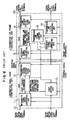
- FIG. 8 shows an arrangement of the transmission apparatus 32 shown in FIG. 7.
- an input terminal 10 to which a digitized information signal is input.
- the digitized information signal applied to the input terminal 10 is supplied to an information signal speed converting unit 11, in which it is converted in speed.
- the output signal from the information signal speed converting unit 11 is supplied to an information signal header synthesizing unit 12.
- a staff control unit 13 there is provided a staff control unit 13.
- the information signal speed converting unit 11, the information signal header synthesizing unit 12 and the staff control unit 13 constitute the information signal frame constructing unit 3.
- An interface signal speed converting unit 15 converts a speed of an information signal supplied thereto, and supplies the information signal thus converted to a transmission line header synthesizing unit 16.
- An interface signal clock generating unit 17 is formed of some suitable means, such as a subsidiary oscillator or the like. There is shown a transmission line frame control unit 18.
- a transmission line clock generating unit 19 is formed of an independent oscillator.
- the interface signal speed converting unit 15, the transmission line header synthesizing unit 16, the interface signal clock generating unit 17, the transmission line frame control unit 18 and the transmission line clock generating unit 19 constitute the transmission line frame constructing unit 4.
- the output of the transmission line frame constructing unit 4 is delivered from a transmission line output terminal 20.
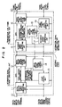
- FIG. 9 shows an arrangement of the reception apparatus 33 shown in FIG. 7.
- a transmission line input terminal 21 a transmission line frame synchronization detection protecting unit 22 and a transmission line frame control unit 23.
- An interface signal speed converting unit 24 effects the speed conversion on the input signal to output an interface signal.
- An interface signal clock generating unit 25 is formed of some suitable means, such as a subsidiary oscillator or the like.
- the transmission line frame synchronization detection protecting unit 22, the transmission line frame control unit 23, the interface signal speed converting unit 24 and the interface signal clock generating unit 25 constitute the transmission line frame analyzing unit 6.
- a staff control unit 28 There is shown a staff control unit 28.
- An information signal speed converting unit 29 effects the speed conversion on the input signal to output an information signal.
- An information signal clock generating unit 30 is formed of some suitable means, such as a subsidiary oscillator or the like.
- the staff control unit 28, the information signal speed converting unit 29 and the information signal clock generating unit 30 constitute the information signal frame analyzing unit 7.
- the output signal from the information signal frame analyzing unit 7 is delivered from a digital information output terminal 31.
- an information header 61 which includes frame synchronizing information of the information signal and staff control information, though not shown.
- an information signal data area 62 which includes 2 words of staff words (10-bit length) 63, 64.
- the information signal header 61, the information signal data area and the staff words 63, 64 constitute a 250-byte information frame 65.
- a transmission line header 66 and a transmission line data area 67 are provided.
- the transmission line data area 67 includes therein a reserve area 69 that is used for future expansion.
- the information signal frame 65 is located in the transmission line data area 67 at its arbitrary position except the portion of the reserve area 69.
- the transmission line header 66 and the transmission line data area 67 constitute a transmission line frame 68.
- a transmission apparatus shown in FIG. 11 is different from the transmission apparatus shown in FIG. 7 only in the arrangements of the transmission apparatus 32 and the reception apparatus 33.
- FIG. 12 which illustrates the arrangement of the transmission apparatus 32
- an information signal frame control unit 14 As shown in FIG. 13 which illustrates the arrangement of the reception apparatus 33, there are provided an information signal frame synchronization detection protecting unit 26 and an information signal frame control unit 27.
- FIGS. 7, 8 and 9 Parts and elements identical to those of FIGS. 7, 8 and 9 are marked with the same references and therefore need not be described in detail.
- An analog information signal such as a video signal or the like
- the information signal input terminal 1 is converted by the A/D converting unit 2 into a digital signal.
- the digital video signal is input to the information signal frame constructing unit 3 in the transmission apparatus 32 from the digital information signal input terminal 10.
- the staff control unit 13 effects the speed difference detection and the staff control
- the information signal speed converting unit 11 effects the speed conversion to the interface speed and the staff insertion
- the information signal header synthesizing unit 12 effects the addition of the information signal header 52, such as the staff control information or the like, respectively.
- the signal thus converted into the interface speed is input to the transmission line frame constructing unit 4.
- information signal frame control information such as the header addition position or the like, and the interface signal clock are transmitted from the transmission line frame constructing unit 4 to the information signal frame constructing unit 3.
- the interface signal speed converting unit 15 effects the speed conversion to the transmission line speed
- the transmission line header synthesizing unit 16 effects the addition of the transmission line header 51.
- a signal is transmitted from the transmission line output terminal 20 to the transmission line 5.
- the signal on the transmission line 5 is arranged as the transmission line frame 56 shown in FIG. 6 and then transmitted.
- the transmission line signal from the transmission line input terminal 21 is input to the transmission line frame analyzing unit 6, and the frame synchronization of the transmission line frame 56 is established by the transmission line frame synchronization detection protecting unit 22.
- the signal that had been converted by the interface signal speed converting unit 24 into the interface speed is input to the information signal frame analyzing unit 7 together with the frame control information generated by the transmission line frame control unit 22 and the interface signal clock generated by the interface signal clock generating unit 25.
- the information signal frame analyzing unit 7 separates the information signal header 52 by the frame control information, and the staff control unit 28 effects the staff control.
- the digital information signal is restored by the information signal speed converting unit 29 and the information signal clock generating unit 30.
- the digital information signal is transmitted from the digital information signal output terminal 31 to the D/A converting unit 8.
- the D/A converting unit 8 restores the original analog information signal and outputs the same from the information signal output terminal 9.
- an analog information signal such as a video signal or the like
- the digital signal is input to the information signal frame constructing unit 3 in the transmission apparatus 32 from the digital information signal input terminal 10.
- the staff control unit 13 effects the speed difference detection and the control of the staff insertion
- the information signal speed converting unit 11 effects the speed conversion to the interface speed
- the information signal header synthesizing unit 12 effects the addition of the information signal header 61, such as the information signal frame synchronizing information, the staff control information or the like, respectively.
- the signal thus converted into the interface speed is input to the transmission line frame constructing unit 4 under the condition that it constructs the information signal frame 65.
- information signal frame control information such as header addition position information to the information signal header synthesizing unit 12, frame length information and intraframe data amount information to the staff control unit 13, are generated by the information signal frame control unit 14.
- the interface signal speed converting unit 15 effects the speed conversion to the transmission line speed
- the transmission line header synthesizing unit 16 effects the addition to the transmission line header 66, thereby a signal being transmitted to the transmission line 5 from the transmission line output terminal 20.
- the signal on the transmission line 5 is arranged as the transmission frame 58 shown in FIG. 10.
- the signal from the transmission line input terminal 21 is input to the transmission line frame analyzing unit 6, and a frame synchronization in the transmission frame 68 is established by the transmission line frame synchronizing detection protecting unit 22.
- the signal that was converted by the interface signal speed converting unit 24 into the interface speed is input to the information signal frame analyzing unit 7 together with the interface signal clock generated by the interface signal clock generating unit 25.
- the information signal frame analyzing unit 7 the information signal frame synchronizing detection protecting unit 26 establishes the frame synchronization of the information signal frame 65 independently of the transmission line frame 68.
- the information signal header 61 is separated by the information signal frame control information generated by the information signal frame control unit 27, and the staff is removed by using the staff control information provided within the information signal header 61 under the control of the staff control unit 28. Then, the digital information signal clock is restored by the information signal clock generating unit 30 and the header area and the staff are removed by the information signal speed converting unit 29, thereby digital information signal data being restored. The digital information signa data thus restored is transmitted to the D/A converting unit 8 from the digital information signal output terminal 31. The D/A converting unit 8 restores the original analog information signal and outputs the same from the information signal output terminal 9.
- the information signal header can be separated by establishing the frame synchronization of the transmission frame and the information signal can be restored by the staff information obtained.
- the frame synchronization of the information signal frame is established by the information signal frame synchronizing information provided within the information signal header, whereby the information signal header can be separated and the staff information can be obtained, thus to restore the information signal.
- a characteristic curve B in FIG. 5 shows an input frequency fluctuation versus residual jitter characteristic obtained when a video signal that had been digitized at a sampling frequency 14.31818 MHz and a quantization bit of 10 bits is transmitted on the transmission line based on the synchronous digital hierarchy network as an information signal.
- a method of calculating a residual jitter characteristic is reported in a paper Vol. 58, No. 8 (1975), Part A, pp. 538 to 545 edited by the Institute of Electronics, Information and Communication Engineers of Japan. Study of recent reports reveals that the increase of such residual jitter exerts a bad influence on the phase characteristic of an information signal to be transmitted. Particularly, in the video transmission system, the residual jitter appears as a noise caused when a phase of a color subcarrier is modulated, and deteriorates a picture quality (e.g., pp. 287 to 294, a paper Vol. 57, No. 4 (1974), Part A, edited by the Institute of Electronics, Information and Communication Engineers of Japan).
- a characteristic curve A in FIG. 5 shows an input frequency fluctuation versus residual jitter characteristic obtained when a digital video signal having a sampling frequency 14.31818 MHz and a quantization bit of 10 bits is transmitted on the transmission line based on the synchronous digital hierarchy as an information signal.
- the information signal frame synchronizing information within the information signal header must be generated by the information signal frame constructing unit 3 in the transmission apparatus 32. Also, the frame synchronization of the information signal frame must be established by capturing the information signal frame synchronizing information within the information signal header by the information signal frame analyzing unit 7 in the reception apparatus 33. There is then the problem that the scale of the required circuit is increased.
- the aforesaid technical literature has proposed as the system (B) a video frame shown in FIG. 15, i.e., a video frame having a frame length of 250 bytes in which a video transmission area of one line of the C-4 bulk is taken at the unit.
- a transmission frame includes a transmission frame used as a signal processing unit on a transmission line, an information signal frame used as a signal processing unit when information is input to and output from the transmission line, and an information signal header which is a control area of the information signal frame.
- a transmission apparatus includes a transmission frame constructing unit formed of an information signal converting unit, a staff control unit, an information signal frame control unit, and an information signal header synthesizing unit, and a transmission line frame constructing unit formed of a transmission clock generating unit, an interface signal clock generating unit, an interface signal speed converting unit, a transmission line frame control unit and a transmission line header synthesizing unit.
- a reception apparatus includes a transmission line frame analyzing unit formed of a transmission line frame synchronization detection protecting unit, a transmission line frame control unit, an interface signal speed converting unit, and an interface signal clock generating unit, and an information signal frame analyzing unit formed of an information signal frame synchronization protecting unit, an information signal frame control unit, a staff control unit, an information signal speed converting unit, and an information signal clock generating unit.
- a synchronization between a transmission line frame and an information signal frame is established by inputting information signal frame position information generated in the transmission line frame control unit provided within the transmission line frame constructing unit into the information signal frame control unit provided within the information signal frame constructing unit, whereby n (n is a positive integer which is a divisor of a length of area used to transmit data within the transmission line frame) information signal frames having a length which results from dividing a length of an area used to transmit data within the transmission line frame by n are accommodated at an arbitrary position distant from the leading byte of the data area provided within the transmission line frame by some bytes.
- Staff control is carried out at every information signal frame, and a single information signal is transmitted by using n information signal frames.
- a frame synchronization among n information frames located at a fixed position within the transmission line frame by inputtting information signal frame position information generated in the transmission line frame control unit provided within the transmission line frame analyzing unit in the reception apparatus into the information signal frame synchronization protecting unit provided within the information signal frame analyzing unit is established en bloc by using the frame synchronization information of the transmission line frame.
- n (n is a positive integer of a divisor of a length of an area used to transmit data within the transmission line frame) information signal frames having a length which results from dividing a length of an area used to transmit data within the transmission line frame by n are accommodated at an arbitrary position within the data area of the transmission line frame, and staff control is carried out at every information signal frame. Then, a staff ratio which is uniquely determined on the basis of a transmission rate, an information speed and a length of the information signal frame serving as the unit length of staff control is varied by changing the frame number n, whereby a residual jitter can be prevented from being increased without increasing a circuit scale.
- FIGS. 1 to 3 show an arrangement of a digital signal transmission apparatus according to an embodiment of the present invention.
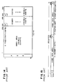
- FIG. 4 shows an example of a format of a transmission frame on a transmission line based on the synchronous digital hierarchy in a digital signal transmission method according to the present invention.
- the digital signal transmission apparatus according to this embodiment is fundamentally the same in arrangement as that of the prior art shown in FIGS. 11, 12 and 13 and like elements and parts are marked with the same references.
- the input terminal to which there is input a video signal as an information signal.
- the analog video signal applied to the input terminal 1 is converted by the A/D converting unit 2 into a digital video signal.
- This digital video signal is supplied to the information frame constructing unit 3 whose output signal is supplied to the transmission line frame constructing unit 4.
- the information signal frame constructing unit 3 and the transmission line frame constructing unit 4 constitute the transmission apparatus 32.
- the transmission line 5 and the arrangement of the transmission signal thereof conforms to the synchronous digital hierarchy.
- the transmission line frame analyzing unit 6 and the information signal frame analyzing unit 7 constitute the reception apparatus 33.
- An output signal of the reception apparatus 33 is converted by the D/A converting unit 8 into an analog signal, and this analog video signal is output from the information signal output terminal 9.
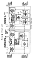
- FIG. 2 shows an arrangement of the transmission apparatus 32 shown in FIG. 1.
- the input terminal 10 to which there is supplied a digitized information signal.
- the information signal speed converting unit 11 effects the speed conversion on the input digitized information signal.
- the information signal header synthesizing unit 12 and the staff control unit 13 constitute the information signal frame constructing unit 3.
- the information signal frame control unit 14 the interface signal speed converting unit 15 which effects the speed conversion on the input interface signal
- the transmission line header synthesizing unit 16 the interface clock generating unit 17 formed of some suitable means, such as a subsidiary oscillator or the like
- the transmission line frame control unit 18, and the transmission clock generating unit 19 formed of an independent oscillator.
- These circuit elements 15 through 19 constitute the transmission line frame constructing unit.
- An output of the transmission line frame constructing unit 4 is delivered from the transmission line output terminal 20.
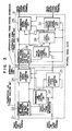
- FIG. 3 shows an arrangement of the reception apparatus shown in FIG. 1.
- the transmission line input terminal 21 the transmission line frame synchronizing detection protecting unit 22, the transmission line frame control unit 23, the interface signal speed converting unit 24 which outputs the interface signal by effecting the speed conversion on the input signal, and the interface signal clock generating unit 25 formed of some suitable means, such as a subsidiary oscillator or the like.
- the above circuit elements 22 to 25 constitute the transmission line frame analyzing unit 6.
- the information signal frame synchronization protecting unit 26 the information signal frame control unit 27, the staff control unit 28, the information signal speed converting unit 29 which outputs an information signal by effecting the speed conversion on the input signal, and the information signal clock generating unit 30 formed of some suitable means, such as a subsidiary oscillator or the like.
- the circuit elements 20 to 30 constitute the information signal frame analyzing unit 7. An output signal from the information signal frame analyzing unit 7 is delivered from the digital information signal output terminal 31.
- an information signal header (10-bit length) which includes therein staff control information of the information signal.
- an information signal data area 42 which includes 2 words of staff words (10-bit length).
- the information signal header 41, the information signal data area 42 and the staff words 43, 44 constitute an information signal frame 45.
- a transmission line header 46 and a transmission line data area 46 are provided.
- the transmission line data area 47 includes therein a reserve area 49 for future expansion.
- the transmission line header 46 and the transmission line data area 47 constitute a transmission line frame 48.
- the information signal frame 45 corresponds to one row (250-byte length) of the transmission line data area 47 and is located within the transmission line data area 47 at its particular position.
- an analog information signal such as a video signal or the like, is input to the information signal input terminal 1.
- This analog information signal is converted by the A/D converting unit 2 into the digital signal, and then input to the information signal frame constructing unit 3 in the transmission apparatus 32 from the digital information signal input terminal 10.
- the staff control unit 13 detects a speed difference between the information signal clock and the interface signal clock and also effects the staff insertion to the information signal data
- the information signal speed converting unit 11 effects the speed conversion from the information signal speed to the interface signal speed
- the information signal header synthesizing unit 12 effects the addition of the information signal header 41, such as the staff control information or the like, respectively.
- the signal that was converted into the interface speed as described above is output from the information signal frame constructing unit 3 under the condition that it constructs the information signal frame 45, and then input to the transmission line frame constructing unit 4.
- Information signal frame control information such as the header addition position information to the information signal header synthesizing unit 12 and information signal frame length information and information signal intraframe data amount information relative to the staff control unit 13 are generate by the information signal frame control unit 14.
- the interface clock signal and information signal frame position information that instructs the position of the information signal frame within the information transmission area of the transmission line frame 48 are transmitted to the information signal frame constructing unit 3 from the transmission line frame constructing unit 4.
- This information signal frame position information a position at which the information signal frame 45 is located in the transmission frame 48 is determined, and a synchronization between the transmission line frame 48 and the information signal frame 45 is established.
- the interface signal speed converting unit 15 effect the speed conversion from the interface speed to the transmission line speed
- the transmission line header synthesizing unit 16 effects the addition of the transmission line header 46. Then, a signal is transmitted to the transmission line 5 from the transmission line output terminal 20.
- the signal on the transmission line 5 is constructed similarly to the transmission line frame 48 shown in FIG. 4 and then transmitted.
- the transmission line signal is input to the transmission line frame analyzing unit 6 from the transmission line input terminal 21, and a frame synchronization of the transmission line frame 48 is established by the transmission line frame synchronization detection protecting unit 22.
- the signal that has been converted from the transmission line speed to the interface speed by the interface signal speed converting unit 24 is output from the transmission line frame analyzing unit 6 together with the interface signal clock generated by the interface signal clock generating unit 25 and the information signal frame position information generated by the transmission line frame control unit 23, and then input to the information signal frame analyzing unit 7.
- a position of the information signal that is located at an arbitrary position distant from the leading byte of the data area within the transmission line frame 47 by some bytes is determined by inputting the information signal frame position information to the information signal frame synchronization protecting unit 26 and thus the frame synchronization of the information signal frame 45 is established.
- the information signal header is separated by the information signal frame control information generated by the information signal frame control unit 27, and the staff is removed by the staff control unit 28 on the basis of the information signal frame control information and the staff control information provided within the information signal header.
- the digital information clock is restored by the information signal clock generating unit 30 and the information signal header area and the staff are removed by the information signal speed converting unit 29, whereby the digital information signal data is restored.
- the digital information signal data thus restored is transmitted to the D/A converting unit 8 from the digital information signal output terminal 31.
- the D/A converting unit 8 restores the original analog information signal, and outputs the same from the information signal output terminal 9.
- the synchronization between the transmission line frame 48 and the information signal frame 45 is established by inputting the information signal frame position information generated in the transmission line frame control unit 18 provided within the transmission line frame constructing unit 4 into the information signal frame control unit 14 provided within the information signal frame constructing unit 3, whereby n information signal frames 45 of frame length which results from diving the length of the area used in the data transmission within the transmission line frame 48 by n are accommodated at an arbitrary position distant from the leading byte of the data area provided within the data area of the transmission line frame 48 by some bytes. Then, the staff control is effected at every information signal frame 45 and a single information signal is transmitted by using n information signal frames 45.
- the information signal frame position information generated in the transmission line frame control unit 23 provided within the transmission line frame analyzing unit 6 is input to the information signal frame synchronization protecting unit 26 provided within the information signal frame analyzing unit 7, whereby a frame synchronization among the n information signal frames 45 located at the fixed position within the transmission line frame 48 is established en bloc by using the frame synchronization information of the transmission line frame 48. Therefore, the staff rate that is uniquely determined by the transmission rate, the information speed and the length of the information signal frame 45 serving as the unit length of the staff control can be varied by changing the lengths of individual information signal frames 45 without increasing the circuit scale. Moreover, information signal can be transmitted by selecting the value of the frame number n which yields the staff ratio that can prevent the residual jitter from being increased without deteriorating the phase characteristic of the information signal.
- the staff ratio is determined on the basis of the transmission rate, the information speed and the frame length of the information signal frame by the following equation (1): where represents an integer portion of
- the frame length of the information signal frame can be changed by selecting the value of n and the information signal frame which can avoid the residual jitter increasing area can be constructed.
- a characteristic curve A in FIG. 3 shows an input frequency fluctuation versus residual jitter characteristic obtained when a video signal digitized at the sampling frequency of 14.31818 MHz and at the quantization bit of 10 bits is transmitted on the transmission line based on the synchronous digital hierarchy as an information signal.
- n may be 1, 2, 3, 5, 6, 9 and 10.
- the present invention is not limited thereto and the above informations may be held within the staff control units 13, 28 in advance. In this case, the circuit arrangement can be simplified more.
- the length of the area used in actual data transmission in the data area would be changed by providing more than one fixed staff in the data area of the transmission line frame and n information signal frames would be constructed.
- the range in which the staff ratio can be set can be further enlarged by enlarging the range of selecting the values of n. In this selection range, the value of n which can provide a staff ratio at which the residual jitter can be prevented from being increased can be selected.
- n information signal frames having a length which results from dividing the length of the area used in data transmission within the transmission line frame by n are located at the arbitrary position within the data area of the transmission line frame. Then, the staff control is carried out at every information signal frame, and the staff ratio which is uniquely determined on the basis of the transmission rate, the information speed and the information signal frame length serving as the unit length of the staff control is varied by changing the frame number n, whereby the residual jitter can be prevented from being increased without increasing the circuit scale and the information signal can be transmitted without deteriorating the quality.
Landscapes
- Engineering & Computer Science (AREA)
- Signal Processing (AREA)
- Computer Networks & Wireless Communication (AREA)
- Multimedia (AREA)
- Time-Division Multiplex Systems (AREA)
- Two-Way Televisions, Distribution Of Moving Picture Or The Like (AREA)
- Synchronisation In Digital Transmission Systems (AREA)
Applications Claiming Priority (2)
| Application Number | Priority Date | Filing Date | Title |
|---|---|---|---|
| JP5052427A JPH06268625A (ja) | 1993-03-12 | 1993-03-12 | ディジタル信号伝送方法および送受信装置および伝送装 置 |
| JP52427/93 | 1993-03-12 |
Publications (2)
| Publication Number | Publication Date |
|---|---|
| EP0615359A2 true EP0615359A2 (fr) | 1994-09-14 |
| EP0615359A3 EP0615359A3 (fr) | 1995-10-25 |
Family
ID=12914481
Family Applications (1)
| Application Number | Title | Priority Date | Filing Date |
|---|---|---|---|
| EP94301651A Withdrawn EP0615359A3 (fr) | 1993-03-12 | 1994-03-09 | Procédé et dispositif de transmission et de réception d'un signal numérique avec justification. |
Country Status (3)
| Country | Link |
|---|---|
| US (1) | US5434890A (fr) |
| EP (1) | EP0615359A3 (fr) |
| JP (1) | JPH06268625A (fr) |
Families Citing this family (8)
| Publication number | Priority date | Publication date | Assignee | Title |
|---|---|---|---|---|
| SE515335C2 (sv) * | 1993-09-14 | 2001-07-16 | Nec Corp | Hastighetskonverteringsanordning som kan fastställa en tranmissionshastighet alltefter önskan |
| US5572515A (en) * | 1994-12-28 | 1996-11-05 | Tektronix, Inc. | Sonet/SDH signal recognition and selection |
| US5757869A (en) * | 1995-07-28 | 1998-05-26 | Adtran, Inc. | Apparatus and method for detecting frame synchronization pattern/word in bit-stuffed digital data frame |
| JP3488017B2 (ja) * | 1996-03-29 | 2004-01-19 | 富士通株式会社 | フレーム送受信方法及び装置 |
| JP3419345B2 (ja) * | 1999-05-28 | 2003-06-23 | 日本電気株式会社 | パルススタッフ同期方式における低次群信号のクロック再生方法および回路 |
| IL141632A (en) * | 2001-02-25 | 2005-12-18 | Eci Telecom Ltd | Method of and system for video transmission over asynchronous transmission technology network |
| US8789081B2 (en) * | 2011-09-02 | 2014-07-22 | Verizon Patent And Licensing Inc. | Video quality scoring |
| JP6249311B2 (ja) * | 2016-08-30 | 2017-12-20 | マクセル株式会社 | 出力装置 |
Family Cites Families (8)
| Publication number | Priority date | Publication date | Assignee | Title |
|---|---|---|---|---|
| DE2412962B2 (de) * | 1974-03-18 | 1976-02-26 | Siemens AG, 1000 Berlin und 8000 München | Verfahren zur zeitmultiplex-uebertragung von daten |
| EP0214352B1 (fr) * | 1985-08-13 | 1990-10-24 | International Business Machines Corporation | Méthode et système de transport adaptatif pour la commutation circuit/paquet |
| GB9012436D0 (en) * | 1990-06-04 | 1990-07-25 | Plessey Telecomm | Sdh rejustification |
| FR2668323B1 (fr) * | 1990-10-17 | 1993-01-15 | Telecommunications Sa | Dispositif de reduction de la gigue due aux sauts de pointeurs dans un reseau de telecommunications numeriques. |
| US5268936A (en) * | 1991-07-08 | 1993-12-07 | At&T Bell Laboratories | Synchronous digital signal to asynchronous digital signal desynchronizer |
| JP2723699B2 (ja) * | 1991-07-31 | 1998-03-09 | 日本電気株式会社 | Tu−3ポインター付替処理方式 |
| US5231649A (en) * | 1991-08-08 | 1993-07-27 | Ascend Communications, Inc. | Method and apparatus for dynamic bandwidth allocation in a digital communication session |
| JPH05167551A (ja) * | 1991-12-18 | 1993-07-02 | Fujitsu Ltd | 同期通信システムにおけるポインターの付け替え方式 |
-
1993
- 1993-03-12 JP JP5052427A patent/JPH06268625A/ja active Pending
-
1994
- 1994-03-08 US US08/207,417 patent/US5434890A/en not_active Expired - Fee Related
- 1994-03-09 EP EP94301651A patent/EP0615359A3/fr not_active Withdrawn
Also Published As
| Publication number | Publication date |
|---|---|
| US5434890A (en) | 1995-07-18 |
| JPH06268625A (ja) | 1994-09-22 |
| EP0615359A3 (fr) | 1995-10-25 |
Similar Documents
| Publication | Publication Date | Title |
|---|---|---|
| CA2031054C (fr) | Methode de multiplexage et de demultiplexage a inversion | |
| CA1210537A (fr) | Methode de transmission de signaux video et audio au moyen d'un systeme de transmission numerique | |
| US4631720A (en) | Service integrated transmission system | |
| EP0800295A2 (fr) | Procédé et dispositif pour la transmission de paquets de données | |
| JPS59122161A (ja) | ブロ−ドバンドネツトワ−クシステム | |
| JPH0591076A (ja) | 同期デイジタルハイアラーキ用伝送装置 | |
| EP0450269B1 (fr) | Dispositif de boucle à verrouillage de phase | |
| US8104067B2 (en) | Apparatus for receiving and playing back data | |
| US4731646A (en) | Moving-image coder with self-identification of the stuffing characters | |
| US5434890A (en) | Method of transmitting a digital signal, digital signal transmission and reception apparatus and digital signal transmission apparatus | |
| RU2155452C2 (ru) | Устройство восстановления синхронизации для синхронной цифровой иерархической системы передачи данных | |
| US5583574A (en) | Video-data transmitter, video-data receiver, and video-data transceiver for connecting parallel video-data into serial video-data and vice versa | |
| EP0302112A1 (fr) | Dispositif diviseur multiplex dans un systeme de multiplexage synchrone | |
| EP0573861B1 (fr) | Système de radiocommunication de signaux numériques d'une hiérarchie synchrone et dispositif de transmission et réception correspondant | |
| US5444711A (en) | HDTV signal transmssion apparatus | |
| US7400592B1 (en) | Picture distribution system and method thereof | |
| US20040070688A1 (en) | Method of video transmission over a synchronous transmission technology network | |
| US8436938B1 (en) | Device and method for receiving data transmitted by means of an asynchronous data transmission technique | |
| US4769809A (en) | Method of and circuit arrangement for through-switching broadband digital signals without phase jump in a synchronous broadband communication network | |
| EP0063639A2 (fr) | Système de communication numérique à bande large | |
| JP2677198B2 (ja) | 無線通信方式 | |
| KR100199960B1 (ko) | 동기 클럭 생성 및 재생장치 | |
| JP2707990B2 (ja) | ディジタル信号伝送方法及びそれに用いる送信装置と受信装置 | |
| JP2605435B2 (ja) | Pcm伝送装置とpcm受信装置およびディジタル・オーディオ・インターフェース・フォーマット・データ伝送装置とディジタル・オーディオ・インターフェース・フォーマット・データ受信装置 | |
| JPH05227115A (ja) | ディジタル信号伝送方法および装置 |
Legal Events
| Date | Code | Title | Description |
|---|---|---|---|
| PUAI | Public reference made under article 153(3) epc to a published international application that has entered the european phase |
Free format text: ORIGINAL CODE: 0009012 |
|
| 17P | Request for examination filed |
Effective date: 19940319 |
|
| AK | Designated contracting states |
Kind code of ref document: A2 Designated state(s): DE FR GB |
|
| PUAL | Search report despatched |
Free format text: ORIGINAL CODE: 0009013 |
|
| AK | Designated contracting states |
Kind code of ref document: A3 Designated state(s): DE FR GB |
|
| GRAH | Despatch of communication of intention to grant a patent |
Free format text: ORIGINAL CODE: EPIDOS IGRA |
|
| STAA | Information on the status of an ep patent application or granted ep patent |
Free format text: STATUS: THE APPLICATION IS DEEMED TO BE WITHDRAWN |
|
| 18D | Application deemed to be withdrawn |
Effective date: 20021015 |