EP0615604B1 - Vorrichtung zum einbringen von zuluft und zum ausbringen von abluft - Google Patents
Vorrichtung zum einbringen von zuluft und zum ausbringen von abluft Download PDFInfo
- Publication number
- EP0615604B1 EP0615604B1 EP92924670A EP92924670A EP0615604B1 EP 0615604 B1 EP0615604 B1 EP 0615604B1 EP 92924670 A EP92924670 A EP 92924670A EP 92924670 A EP92924670 A EP 92924670A EP 0615604 B1 EP0615604 B1 EP 0615604B1
- Authority
- EP
- European Patent Office
- Prior art keywords
- air
- exhaust air
- housing
- vanes
- exhaust
- Prior art date
- Legal status (The legal status is an assumption and is not a legal conclusion. Google has not performed a legal analysis and makes no representation as to the accuracy of the status listed.)
- Expired - Lifetime
Links
- 238000000605 extraction Methods 0.000 title 1
- 238000011109 contamination Methods 0.000 description 2
- 241000446313 Lamella Species 0.000 description 1
- 238000005452 bending Methods 0.000 description 1
- 230000005494 condensation Effects 0.000 description 1
- 238000009833 condensation Methods 0.000 description 1
- 239000002184 metal Substances 0.000 description 1
- 230000002093 peripheral effect Effects 0.000 description 1
Images

Classifications
-
- F—MECHANICAL ENGINEERING; LIGHTING; HEATING; WEAPONS; BLASTING
- F24—HEATING; RANGES; VENTILATING
- F24F—AIR-CONDITIONING; AIR-HUMIDIFICATION; VENTILATION; USE OF AIR CURRENTS FOR SCREENING
- F24F7/00—Ventilation
- F24F7/04—Ventilation with ducting systems, e.g. by double walls; with natural circulation
- F24F7/06—Ventilation with ducting systems, e.g. by double walls; with natural circulation with forced air circulation, e.g. by fan positioning of a ventilator in or against a conduit
- F24F7/08—Ventilation with ducting systems, e.g. by double walls; with natural circulation with forced air circulation, e.g. by fan positioning of a ventilator in or against a conduit with separate ducts for supplied and exhausted air with provisions for reversal of the input and output systems
-
- E—FIXED CONSTRUCTIONS
- E06—DOORS, WINDOWS, SHUTTERS, OR ROLLER BLINDS IN GENERAL; LADDERS
- E06B—FIXED OR MOVABLE CLOSURES FOR OPENINGS IN BUILDINGS, VEHICLES, FENCES OR LIKE ENCLOSURES IN GENERAL, e.g. DOORS, WINDOWS, BLINDS, GATES
- E06B7/00—Special arrangements or measures in connection with doors or windows
- E06B7/02—Special arrangements or measures in connection with doors or windows for providing ventilation, e.g. through double windows; Arrangement of ventilation roses
-
- E—FIXED CONSTRUCTIONS
- E06—DOORS, WINDOWS, SHUTTERS, OR ROLLER BLINDS IN GENERAL; LADDERS
- E06B—FIXED OR MOVABLE CLOSURES FOR OPENINGS IN BUILDINGS, VEHICLES, FENCES OR LIKE ENCLOSURES IN GENERAL, e.g. DOORS, WINDOWS, BLINDS, GATES
- E06B7/00—Special arrangements or measures in connection with doors or windows
- E06B7/02—Special arrangements or measures in connection with doors or windows for providing ventilation, e.g. through double windows; Arrangement of ventilation roses
- E06B7/10—Special arrangements or measures in connection with doors or windows for providing ventilation, e.g. through double windows; Arrangement of ventilation roses by special construction of the frame members
-
- F—MECHANICAL ENGINEERING; LIGHTING; HEATING; WEAPONS; BLASTING
- F24—HEATING; RANGES; VENTILATING
- F24F—AIR-CONDITIONING; AIR-HUMIDIFICATION; VENTILATION; USE OF AIR CURRENTS FOR SCREENING
- F24F13/00—Details common to, or for air-conditioning, air-humidification, ventilation or use of air currents for screening
- F24F13/08—Air-flow control members, e.g. louvres, grilles, flaps or guide plates
Definitions
- the following invention relates to a device for introducing supply air and for extracting exhaust air into or from a room with a window frame, behind which there is at least one housing, slanted slats for the supply air being arranged in the window frame in addition to nozzles for the exhaust air.
- a combined supply and exhaust air grille is already known from EP-A-0 379 188 and DE-OS 39 01 544.0, in which nozzles are arranged next to a slotted plate.
- the nozzle protrudes very far above the level of the supply and exhaust air grille, which is very unattractive.
- the slots in the slotted plate have the disadvantage that they produce hissing noises when intake air is drawn in, which are undesirable.
- the present invention has for its object to improve the supply and exhaust air grille so far that the do not interfere with each other and yet the entire device receives a good aesthetic design.
- the lamellae are formed from stamped metal sheets and are bent from the lamellae receiving grooves, through which, in the position of use, rods which are fastened in the walls of the housing are pushed.
- the slats are preferably set at an angle, so that rain, which strikes the slats, for example, is drained away from them again.
- the lowest slat should preferably protrude so far over the frame and thus also over a house wall that the dripping rain is drained away from this house wall as far as possible. This significantly reduces the risk of the house wall becoming dirty.
- the nozzles are long-throw nozzles. These long throw nozzles have the main advantage that they are the Throw away the exhaust air very far so that the exhaust air cannot mix again with the supply air. This short circuit is avoided.
- the nozzle mouth of the long-throw nozzle is preferably located approximately in the plane of the window frame or protrudes only slightly above the window frame.
- the entire long-range nozzle is essentially embedded in the housing, so that the entire grille is given a very elegant design.
- a bird protection grille and / or a filter mat is to be arranged behind the slats and / or the nozzles in the housing. This prevents birds from entering the room or, in particular, cleans the supply air to be introduced.
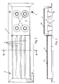
- FIG. 1 has a peripheral frame 1, which can be made of individual miter-cut strips, which are optionally penetrated by corresponding mounting holes 2.
- the housing 3 is used for introducing supply air into, for example, a living space, while the housing 4 is dedicated to extracting exhaust air from, for example, a living space.
- a guide channel for the supply and exhaust air can also be connected to both housings 3 and 4.
- slats 5 which, as can be seen in particular in FIG. 3, are inclined.
- horizontal bars 6 are provided in the housing 3, which in the position of use sit in a receiving groove 7 formed by bending the lamella 5.
- the slats 5 are inclined for the purpose of rain repellency.
- nozzles 8 are preferably used and attached to a support plate 9.
- four nozzles 8 are shown, but there may also be fewer or more nozzles, depending on the amount of exhaust air that has to be discharged from a room.
- these exhaust air nozzles 8 are conically shaped and arranged substantially recessed in the housing 4. This means that a nozzle mouth 10 does not protrude or only very slightly protrudes beyond a plane 11 of the housing 4 or the frame 1.
- the arrangement of nozzles 8 next to the fins of the supply air housing 3 has the advantage that the exhaust air is thrown away very far from the blow-out point. On the one hand, there is no contamination of the house wall by condensation or the like. on the other hand, there is no risk of a short circuit between the exhaust air and supply air. This means that the exhaust air volume cannot mix with the supply air volume.
Landscapes
- Engineering & Computer Science (AREA)
- Combustion & Propulsion (AREA)
- Mechanical Engineering (AREA)
- General Engineering & Computer Science (AREA)
- Civil Engineering (AREA)
- Structural Engineering (AREA)
- Chemical & Material Sciences (AREA)
- Specific Sealing Or Ventilating Devices For Doors And Windows (AREA)
- Ventilation (AREA)
- Storage Of Harvested Produce (AREA)
- Duct Arrangements (AREA)
- Refuse Collection And Transfer (AREA)
- Current-Collector Devices For Electrically Propelled Vehicles (AREA)
- Magnetic Resonance Imaging Apparatus (AREA)
- Motor Or Generator Cooling System (AREA)
- Drying Of Solid Materials (AREA)
- Manufacturing And Processing Devices For Dough (AREA)
- Preliminary Treatment Of Fibers (AREA)
- Devices For Use In Laboratory Experiments (AREA)
- Treatment Of Fiber Materials (AREA)
Description
- Die nachfolgende Erfindung betrifft eine Vorrichtung zum Einbringen von Zuluft und zum Ausbringen von Abluft in oder aus einem Raum mit einem Blendrahmen, hinter welchem sich zumindest ein Gehäuse befindet, wobei im Blendrahmen neben Düsen für die Abluft schräggestellte Lamellen für die Zuluft angeordnet sind.
- Aus der EP-A-0 379 188 bzw. der DE-OS 39 01 544.0 ist bereits ein kombiniertes Zu- und Abluftgitter bekannt, bei welchem neben einer Schlitzplatte Düsen angeordnet sind. Dabei steht die Düse sehr weit über die Ebene des Zu- und Abluftgitters hervor, was sehr unschön ist. Ferner haben die Schlitze in der Schlitzplatte den Nachteil, daß sie beim Ansaugen von Zuluft zischende Geräusche erzeugen, die unerwünscht sind.
- Der vorliegenden Erfindung liegt die Aufgabe zugrunde, das Zu- und Abluftgitter so weit zu verbessern, daß sich die beiden Funktionen gegenseitig nicht stören und dennoch die gesamte Vorrichtung eine gute ästhetische Formgestaltung erhält.
- Zur Lösung dieser Aufgabe führt, daß die Lamellen aus gestanzten Blechen geformt und von den Lamellen Aufnahmenuten abgekantet sind, durch welche in Gebrauchslage in Wänden des Gehäuses befestigte Stäbe geschoben sind.
- Bevorzugt sind die Lamellen schräg gestellt, so daß Regen, welcher beispielsweise an die Lamellen schlägt, von diesen wieder nach außen abgeleitet wird. Dabei soll bevorzugt die unterste Lamelle so weit über den Blendrahmen und damit auch über eine Hauswand hervorstehen, daß der abtropfende Regen von dieser Hauswand möglichst weit abgeleitet wird. Hierdurch wird die Gefahr einer Verschmutzung der Hauswand wesentlich vermindert.
- Bei den Düsen handelt es sich um Weitwurfdüsen. Diese Weitwurfdüsen haben den wesentlichen Vorteil, daß sie die Abluft sehr weit wegwerfen, so daß sich die Abluft nicht wieder mit der Zuluft vermischen kann. Dieser Kurzschluß wird vermieden.
- Der Düsenmund der Weitwurfdüse befindet sich bevorzugt etwa in der Ebene des Blendrahmens oder steht nur geringfügig über dem Blendrahmen hervor. D.h., die gesamte Weitwurfdüse ist im wesentlichen in das Gehäuse eingelassen, so daß das gesamte Gitter eine sehr formschöne Ausgestaltung erhält.
- In einem weiteren Ausführungsbeispiel der Erfindung soll hinter den Lamellen und/oder den Düsen in dem Gehäuse noch ein Vogelschutzgitter und/oder eine Filtermatte angeordnet sein. Hierdurch wird ein Eindringen von Vögeln in den Raum vermieden bzw. insbesondere die einzubringende Zuluft gereinigt.
- Weitere Vorteile, Merkmale und Einzelheiten der Erfindung ergeben sich aus der nachfolgenden Beschreibung bevorzugter Ausführungsbeispiele sowie anhand der Zeichnung; diese zeigt in
- Fig. 1 eine Draufsicht auf ein erfindungsgemäßes Zu- und Abluftgitter;
- Fig. 2 eine Seitenansicht des Zu- und Abluftgitters gem. Fig. 1;
- Fig. 3 einen Querschnitt durch das Zu- und Abluftgitter entlang Linie III - III in Fig. 1.
- Ein erfindungsgemäßes Zu- und Abluftgitter P weist gem. Fig. 1 einen umlaufenden Blendrahmen 1 auf, der aus einzelnen auf Gehrung geschnittenen Streifen hergestellt sein kann, welche gegebenenfalls noch von entsprechenden Befestigungslöchern 2 durchsetzt sind.
- Hinter diesem Blendrahmen 1 befinden sich zwei Gehäuse 3 und 4. Das Gehäuse 3 dient dem Einbringen von Zuluft in beispielsweise einen Wohnraum, während das Gehäuse 4 dem Ausbringen von Abluft aus beispielsweise einem Wohnraum gewidmet ist. An beide Gehäuse 3 und 4 kann auch jeweils ein Führungskanal für die Zu- bzw. Abluft angeschlossen sein.
- In dem Zuluftgehäuse 3 befinden sich Lamellen 5, welche, wie insbesondere in Fig. 3 ersichtlich, schräg gestellt sind. Zu ihrer Befestigung sind in dem Gehäuse 3 waagrechte Stäbe 6 vorgesehen, welche in Gebrauchslage in einer durch Abkantung der Lamelle 5 angeformten Aufnahme- nut 7 sitzen. Die Schrägstellung der Lamellen 5 erfolgt zum Zwecke der Regenabweisung.
- Eine unterste Lamelle 5 a ragt noch über den Blendrahmen 1 hinaus, so daß ein abtropfender Regen von den anderen Lamellen 5 durch diese letzte Lamelle 5 a weg von dem Blendrahmen 1 und damit auch weg von einer Wand ablaufen kann. Hierdurch wird eine Verschmutzungsgefahr der Wand wesentlich vermindert.
- In dem Abluftgehäuse 4 neben dem Zuluftgehäuse 3 sind dagegen bevorzugt Düsen 8 eingesetzt und auf einer Tragplatte 9 befestigt. Im vorliegenden Ausführungsbeispiel sind vier Düsen 8 gezeigt, jedoch können es auch weniger oder mehr Düsen sein, je nach der Abluftmenge, welche aus einem Raum ausgelassen werden muss. Diese Abluftdüsen 8 sind bekanntermaßen konisch geformt und im wesentlichen versenkt in dem Gehäuse 4 angeordnet. Das bedeutet, daß ein Düsenmund 10 nicht oder nur ganz geringfügig über eine Ebene 11 des Gehäuses 4 bzw. des Blendrahmens 1 hervorsteht.
- Die Anordnung von Düsen 8 neben den Lamellen des Zuluftgehäuses 3 hat den Vorteil, daß die Abluft sehr weit von der Ausblasstelle weggeworfen wird. Zum einen findet damit auch keine Verschmutzung der Hauswand durch Kondenswasser od.dgl. statt, zum anderen besteht nicht die Gefahr eines Kurzschlusses zwischen Abluft und Zuluft. Die Abluftmenge kann sich dadurch nicht mit der Zuluftmenge vermischen.
- Ein derartiges kombiniertes Zu- und Abluftgitter hat vor allem auch den Vorteil, daß nur ein einziger Durchbruch in einer Wand geschaffen werden muß, was bei den heutigen Fassaden sehr wichtig ist. Heute wird gewünscht, daß möglichst wenig Öffnungen nach draußen führen. Ferner sieht das gesamte Gitter architektonisch sehr gut aus.
- Des weiteren ist daran gedacht, daß hinter den Lamellen bzw. Düsen auch ein Vogelschutzgitter und/oder eine Filtermatte 12 eingesetzt wird, damit die geförderte Luft entsprechend den gewünschten Bedürfnissen gereinigt wird. Dies gilt vor allem für die Zuluft.
Claims (3)
- Vorrichtung zum Einbringen von Zuluft und zum Ausbringen von Abluft in oder aus einem Raum mit einem Blendrahmen (1), hinter welchem sich zumindest ein Gehäuse (3) befindet, wobei im Blendrahmen (1) neben Düsen (8) für die Abluft schräggestellte Lamellen (5) für die Zuluft angeordnet sind,
dadurch gekennzeichnet,
daß die Lamellen (5) aus gestanzten Blechen geformt und von den Lamellen (5) Aufnahmenuten (7) abgekantet sind, durch welche in Gebrauchslage in Wänden des Gehäuses (3) befestigte Stäbe (6) geschoben sind. - Vorrichtung nach Anspruch 1, dadurch gekennzeichnet, daß ein Düsenmund (10) nicht oder nur geringfügig über eine Ebene (11) des Blendrahmens hinaussteht.
- Vorrichtung nach Anspruch 1 oder 2, dadurch gekennzeichnet, daß sich hinter den Lamellen (5) und/oder den Düsen (8) in den Gehäusen (3, 4) Vogelschutzgitter und/oder Filtermatten (12) befinden.
Applications Claiming Priority (3)
| Application Number | Priority Date | Filing Date | Title |
|---|---|---|---|
| DE9115489U DE9115489U1 (de) | 1991-12-13 | 1991-12-13 | Vorrichtung zum Einbringen von Zuluft und zum Ausbringen von Abluft |
| DE9115489U | 1991-12-13 | ||
| PCT/EP1992/002811 WO1993012392A1 (de) | 1991-12-13 | 1992-12-05 | Vorrichtung zum einbringen von zuluft und zum ausbringen von abluft |
Publications (2)
| Publication Number | Publication Date |
|---|---|
| EP0615604A1 EP0615604A1 (de) | 1994-09-21 |
| EP0615604B1 true EP0615604B1 (de) | 1995-07-26 |
Family
ID=6874197
Family Applications (1)
| Application Number | Title | Priority Date | Filing Date |
|---|---|---|---|
| EP92924670A Expired - Lifetime EP0615604B1 (de) | 1991-12-13 | 1992-12-05 | Vorrichtung zum einbringen von zuluft und zum ausbringen von abluft |
Country Status (5)
| Country | Link |
|---|---|
| EP (1) | EP0615604B1 (de) |
| AT (1) | ATE125616T1 (de) |
| DE (2) | DE9115489U1 (de) |
| ES (1) | ES2076792T3 (de) |
| WO (1) | WO1993012392A1 (de) |
Families Citing this family (3)
| Publication number | Priority date | Publication date | Assignee | Title |
|---|---|---|---|---|
| US6447389B1 (en) * | 2001-05-08 | 2002-09-10 | Chin-Sheng Kuo | Wind-hole base of a blower for an air conditioner |
| DE10212853B4 (de) * | 2002-03-22 | 2005-03-03 | Maschinenfabrik Georg Kiefer Gmbh | Lüftungsbauelement sowie Verfahren zum Einbau eines Lüftungsbauelementes |
| DE102006060894A1 (de) * | 2006-12-22 | 2008-06-26 | Ltg Ag | Verfahren und Vorrichtung zum Ansaugen von Außenluft |
Family Cites Families (2)
| Publication number | Priority date | Publication date | Assignee | Title |
|---|---|---|---|---|
| NL8802422A (nl) * | 1988-10-03 | 1990-05-01 | Casparus Wilhelmus De Waal | Luchtrooster. |
| JPH02233935A (ja) * | 1989-01-20 | 1990-09-17 | Schako Metallwarenfab Ferdinand Schad Kg | 給気排気兼用装置 |
-
1991
- 1991-12-13 DE DE9115489U patent/DE9115489U1/de not_active Expired - Lifetime
-
1992
- 1992-12-05 WO PCT/EP1992/002811 patent/WO1993012392A1/de not_active Ceased
- 1992-12-05 ES ES92924670T patent/ES2076792T3/es not_active Expired - Lifetime
- 1992-12-05 AT AT92924670T patent/ATE125616T1/de not_active IP Right Cessation
- 1992-12-05 EP EP92924670A patent/EP0615604B1/de not_active Expired - Lifetime
- 1992-12-05 DE DE59203054T patent/DE59203054D1/de not_active Expired - Fee Related
Also Published As
| Publication number | Publication date |
|---|---|
| ES2076792T3 (es) | 1995-11-01 |
| DE9115489U1 (de) | 1992-04-02 |
| WO1993012392A1 (de) | 1993-06-24 |
| ATE125616T1 (de) | 1995-08-15 |
| DE59203054D1 (de) | 1995-08-31 |
| EP0615604A1 (de) | 1994-09-21 |
Similar Documents
| Publication | Publication Date | Title |
|---|---|---|
| DE19609687C2 (de) | Wandkühlgerät für einen Schaltsschrank mit einem Lüfter und einem Lamellen-Wärmetauscher | |
| EP0386717B1 (de) | Verfahren zum Herstellen eines Lüftungsgitters | |
| DE19734146C2 (de) | Luftzuführeinrichtung | |
| EP0413784A1 (de) | Vorrichtung zum be- und ggfs. auch entlüften eines raumes. | |
| DE3140756A1 (de) | Fenster- oder tuerrahmen fuer wohn-, campingwagen oder dergleichen. | |
| EP0379188B1 (de) | Vorrichtung zum Be- und Entlüften | |
| WO1993012392A1 (de) | Vorrichtung zum einbringen von zuluft und zum ausbringen von abluft | |
| DE19908571C2 (de) | Rolladenaggregat | |
| DE10005964A1 (de) | Vorrichtung zum Verhindern des Eindringens von Zugluft durch eine Öffnung in einem Gebäude | |
| DE1962090A1 (de) | Belueftungseinrichtung | |
| CH660414A5 (de) | Lueftungsvorrichtung zur anordnung an einer gebaeudewand, insbesondere in wohn- und arbeitsraeumen. | |
| DE3490467T (de) | Bedachungssystem | |
| DE3901543A1 (de) | Vorrichtung zur be- und entlueftung | |
| EP0103221B1 (de) | Transportable Beton-Raumzelle | |
| DE2742667A1 (de) | Entlueftungsvorrichtung fuer kraftfahrzeuge | |
| EP0468091B1 (de) | Verfahren zum Herstellen und Montieren von Luftauslässen | |
| EP0106259A2 (de) | Wärmerückgewinnungsanlage für ein Gebäude | |
| DE19903836C5 (de) | Abdeckung für Licht- und/oder Lüftungsschächte sowie Profilstab hierfür | |
| DE68903920T2 (de) | Lueftungsgitter. | |
| DE1505278A1 (de) | Belueftungsvorrichtung fuer Kraftfahrzeugkarosserien | |
| DE202010010610U1 (de) | Lüftungsgitter | |
| WO1996001398A1 (de) | Quellauslass | |
| DE914898C (de) | Belueftungsaufsatz, insbesondere zum Belueften der Innenraeume von Fahrzeugen | |
| DE3106278C2 (de) | Lüftungsvorrichtung für Dächer | |
| DE2411728A1 (de) | Luefterwand zum einbau in die aussenwand eines gebaeudes |
Legal Events
| Date | Code | Title | Description |
|---|---|---|---|
| PUAI | Public reference made under article 153(3) epc to a published international application that has entered the european phase |
Free format text: ORIGINAL CODE: 0009012 |
|
| 17P | Request for examination filed |
Effective date: 19940513 |
|
| AK | Designated contracting states |
Kind code of ref document: A1 Designated state(s): AT BE CH DE ES FR GB IT LI LU NL |
|
| 17Q | First examination report despatched |
Effective date: 19950109 |
|
| GRAA | (expected) grant |
Free format text: ORIGINAL CODE: 0009210 |
|
| AK | Designated contracting states |
Kind code of ref document: B1 Designated state(s): AT BE CH DE ES FR GB IT LI LU NL |
|
| REF | Corresponds to: |
Ref document number: 125616 Country of ref document: AT Date of ref document: 19950815 Kind code of ref document: T |
|
| ITF | It: translation for a ep patent filed | ||
| ET | Fr: translation filed | ||
| REF | Corresponds to: |
Ref document number: 59203054 Country of ref document: DE Date of ref document: 19950831 |
|
| REG | Reference to a national code |
Ref country code: ES Ref legal event code: FG2A Ref document number: 2076792 Country of ref document: ES Kind code of ref document: T3 |
|
| PGFP | Annual fee paid to national office [announced via postgrant information from national office to epo] |
Ref country code: BE Payment date: 19951116 Year of fee payment: 4 |
|
| PGFP | Annual fee paid to national office [announced via postgrant information from national office to epo] |
Ref country code: FR Payment date: 19951120 Year of fee payment: 4 |
|
| PGFP | Annual fee paid to national office [announced via postgrant information from national office to epo] |
Ref country code: AT Payment date: 19951122 Year of fee payment: 4 |
|
| GBT | Gb: translation of ep patent filed (gb section 77(6)(a)/1977) |
Effective date: 19951103 |
|
| PGFP | Annual fee paid to national office [announced via postgrant information from national office to epo] |
Ref country code: ES Payment date: 19951222 Year of fee payment: 4 |
|
| PGFP | Annual fee paid to national office [announced via postgrant information from national office to epo] |
Ref country code: CH Payment date: 19951229 Year of fee payment: 4 |
|
| PG25 | Lapsed in a contracting state [announced via postgrant information from national office to epo] |
Ref country code: LU Free format text: LAPSE BECAUSE OF NON-PAYMENT OF DUE FEES Effective date: 19951231 |
|
| PLBE | No opposition filed within time limit |
Free format text: ORIGINAL CODE: 0009261 |
|
| STAA | Information on the status of an ep patent application or granted ep patent |
Free format text: STATUS: NO OPPOSITION FILED WITHIN TIME LIMIT |
|
| 26N | No opposition filed | ||
| PG25 | Lapsed in a contracting state [announced via postgrant information from national office to epo] |
Ref country code: GB Effective date: 19961205 Ref country code: AT Effective date: 19961205 |
|
| PG25 | Lapsed in a contracting state [announced via postgrant information from national office to epo] |
Ref country code: LI Effective date: 19961231 Ref country code: CH Effective date: 19961231 Ref country code: BE Effective date: 19961231 |
|
| BERE | Be: lapsed |
Owner name: SCHAKO METALLWARENFABRIK FERDINAND SCHAD K.G. Effective date: 19961231 |
|
| PG25 | Lapsed in a contracting state [announced via postgrant information from national office to epo] |
Ref country code: NL Effective date: 19970701 |
|
| GBPC | Gb: european patent ceased through non-payment of renewal fee |
Effective date: 19961205 |
|
| REG | Reference to a national code |
Ref country code: CH Ref legal event code: PL |
|
| PG25 | Lapsed in a contracting state [announced via postgrant information from national office to epo] |
Ref country code: FR Effective date: 19970829 |
|
| NLV4 | Nl: lapsed or anulled due to non-payment of the annual fee |
Effective date: 19970701 |
|
| REG | Reference to a national code |
Ref country code: FR Ref legal event code: ST |
|
| PG25 | Lapsed in a contracting state [announced via postgrant information from national office to epo] |
Ref country code: ES Free format text: LAPSE BECAUSE OF NON-PAYMENT OF DUE FEES Effective date: 19971206 |
|
| REG | Reference to a national code |
Ref country code: ES Ref legal event code: FD2A Effective date: 19980113 |
|
| PG25 | Lapsed in a contracting state [announced via postgrant information from national office to epo] |
Ref country code: IT Free format text: LAPSE BECAUSE OF NON-PAYMENT OF DUE FEES;WARNING: LAPSES OF ITALIAN PATENTS WITH EFFECTIVE DATE BEFORE 2007 MAY HAVE OCCURRED AT ANY TIME BEFORE 2007. THE CORRECT EFFECTIVE DATE MAY BE DIFFERENT FROM THE ONE RECORDED. Effective date: 20051205 |
|
| PGFP | Annual fee paid to national office [announced via postgrant information from national office to epo] |
Ref country code: DE Payment date: 20080229 Year of fee payment: 16 |
|
| PG25 | Lapsed in a contracting state [announced via postgrant information from national office to epo] |
Ref country code: DE Free format text: LAPSE BECAUSE OF NON-PAYMENT OF DUE FEES Effective date: 20090701 |