EP0615607B1 - Appareil optique pour la mesure des distances - Google Patents
Appareil optique pour la mesure des distances Download PDFInfo
- Publication number
- EP0615607B1 EP0615607B1 EP92923049A EP92923049A EP0615607B1 EP 0615607 B1 EP0615607 B1 EP 0615607B1 EP 92923049 A EP92923049 A EP 92923049A EP 92923049 A EP92923049 A EP 92923049A EP 0615607 B1 EP0615607 B1 EP 0615607B1
- Authority
- EP
- European Patent Office
- Prior art keywords
- distance sensor
- optical distance
- sensor according
- measurement
- photodetectors
- Prior art date
- Legal status (The legal status is an assumption and is not a legal conclusion. Google has not performed a legal analysis and makes no representation as to the accuracy of the status listed.)
- Expired - Lifetime
Links
- 230000003287 optical effect Effects 0.000 title claims abstract description 35
- 238000005259 measurement Methods 0.000 claims abstract description 28
- 238000007689 inspection Methods 0.000 claims abstract description 4
- 238000005286 illumination Methods 0.000 claims description 23
- 238000013461 design Methods 0.000 claims description 5
- 238000009826 distribution Methods 0.000 claims description 5
- 239000003086 colorant Substances 0.000 claims description 4
- 238000011144 upstream manufacturing Methods 0.000 claims description 4
- 230000004075 alteration Effects 0.000 claims description 2
- 238000012634 optical imaging Methods 0.000 claims description 2
- 238000000926 separation method Methods 0.000 claims description 2
- 238000004441 surface measurement Methods 0.000 claims description 2
- 230000001747 exhibiting effect Effects 0.000 claims 1
- 210000001747 pupil Anatomy 0.000 claims 1
- 238000000034 method Methods 0.000 abstract description 11
- 230000035945 sensitivity Effects 0.000 abstract description 2
- 230000004446 light reflex Effects 0.000 abstract 1
- 238000001514 detection method Methods 0.000 description 9
- 229910000679 solder Inorganic materials 0.000 description 6
- 238000012360 testing method Methods 0.000 description 4
- 230000008901 benefit Effects 0.000 description 3
- 230000008859 change Effects 0.000 description 3
- 238000006073 displacement reaction Methods 0.000 description 3
- 238000011156 evaluation Methods 0.000 description 3
- 230000008569 process Effects 0.000 description 3
- 238000012545 processing Methods 0.000 description 3
- 239000007787 solid Substances 0.000 description 3
- 238000003491 array Methods 0.000 description 2
- 230000001419 dependent effect Effects 0.000 description 2
- 230000001360 synchronised effect Effects 0.000 description 2
- 230000000712 assembly Effects 0.000 description 1
- 238000000429 assembly Methods 0.000 description 1
- 239000004020 conductor Substances 0.000 description 1
- 238000010276 construction Methods 0.000 description 1
- 238000011109 contamination Methods 0.000 description 1
- 230000008878 coupling Effects 0.000 description 1
- 238000010168 coupling process Methods 0.000 description 1
- 238000005859 coupling reaction Methods 0.000 description 1
- 230000007423 decrease Effects 0.000 description 1
- 230000007547 defect Effects 0.000 description 1
- 238000010586 diagram Methods 0.000 description 1
- 230000000694 effects Effects 0.000 description 1
- 238000005516 engineering process Methods 0.000 description 1
- 238000003384 imaging method Methods 0.000 description 1
- 230000010354 integration Effects 0.000 description 1
- 230000003993 interaction Effects 0.000 description 1
- 238000004519 manufacturing process Methods 0.000 description 1
- 238000004377 microelectronic Methods 0.000 description 1
- 238000012986 modification Methods 0.000 description 1
- 230000004048 modification Effects 0.000 description 1
- 238000012856 packing Methods 0.000 description 1
- 239000002245 particle Substances 0.000 description 1
- 150000003071 polychlorinated biphenyls Chemical class 0.000 description 1
- 238000009420 retrofitting Methods 0.000 description 1
- 238000009827 uniform distribution Methods 0.000 description 1
Images

Classifications
-
- G—PHYSICS
- G01—MEASURING; TESTING
- G01B—MEASURING LENGTH, THICKNESS OR SIMILAR LINEAR DIMENSIONS; MEASURING ANGLES; MEASURING AREAS; MEASURING IRREGULARITIES OF SURFACES OR CONTOURS
- G01B11/00—Measuring arrangements characterised by the use of optical techniques
- G01B11/24—Measuring arrangements characterised by the use of optical techniques for measuring contours or curvatures
-
- G—PHYSICS
- G01—MEASURING; TESTING
- G01B—MEASURING LENGTH, THICKNESS OR SIMILAR LINEAR DIMENSIONS; MEASURING ANGLES; MEASURING AREAS; MEASURING IRREGULARITIES OF SURFACES OR CONTOURS
- G01B11/00—Measuring arrangements characterised by the use of optical techniques
- G01B11/02—Measuring arrangements characterised by the use of optical techniques for measuring length, width or thickness
- G01B11/026—Measuring arrangements characterised by the use of optical techniques for measuring length, width or thickness by measuring distance between sensor and object
-
- G—PHYSICS
- G01—MEASURING; TESTING
- G01B—MEASURING LENGTH, THICKNESS OR SIMILAR LINEAR DIMENSIONS; MEASURING ANGLES; MEASURING AREAS; MEASURING IRREGULARITIES OF SURFACES OR CONTOURS
- G01B11/00—Measuring arrangements characterised by the use of optical techniques
- G01B11/02—Measuring arrangements characterised by the use of optical techniques for measuring length, width or thickness
- G01B11/06—Measuring arrangements characterised by the use of optical techniques for measuring length, width or thickness for measuring thickness ; e.g. of sheet material
- G01B11/0608—Height gauges
Definitions
- the invention relates to an optical distance sensor based on the confocal optical imaging principle for determining height values and for three-dimensional surface measurement.
- Preferred areas of application are, in particular, the inspection of the solder joints and the control of the structure of the component in the case of densely populated electronic printed circuit boards, such as multi-chip modules.
- Devices known hitherto for recording height raster images which consist of a multiplicity of three-dimensionally present points of object surfaces, are essentially based on the so-called triangulation method.
- a laser beam scans the surface of the object.
- the two planar location coordinates of a certain surface point are known from the relative position between the scanning beam or illuminating beam and the printed circuit board.
- the height coordinate of the surface point that is currently being measured is detected by at least one laterally arranged lens in conjunction with a location-sensitive detector.
- the three-dimensional location coordinates of a large number of surface points can thus be determined. Defects can be identified by comparing a recorded surface image with an ideal surface image and taking certain error criteria into account PCBs are recognized automatically.
- Measuring systems available on the market according to the triangulation method have certain configurations by means of which the disadvantages mentioned above can be partially avoided.
- the company Robotic Vision Systems (536 Broadhollow Road, Melville, New York 11747, USA) has used linear photodiode arrays instead of lateral photodiodes to avoid incorrect measurements due to secondary reflections.
- Corresponding evaluation software detects and eliminates incorrect measurements.
- the data rate of the system is reduced strong that this is not suitable for a complete inspection in a process line.
- Matsushita Kotobuki Electric Co., Ltd. (2131 Ohara-minamikata, Kawauchi-machi, Onsen-gun, Ekimeken 791-03, Japan) developed a system in which observation is carried out from eight directions. Suitable algorithms are used to evaluate the detector signals. This increases the detection reliability of shiny surfaces.
- the overall construction is very complex due to the use of approx. Four sensor heads, each with eight detectors, which scan by means of a rapidly rotating disc. In addition, the system cannot measure within deep holes. A resolution greater than 40 »m is not achieved due to mechanical and optical adjustment problems when the sensor head rotates quickly.
- the company Nagoya Electric Works Co., Ltd (550 Takawari, Katori, Tadocho, Kuwana-gun, Mieken 511-01, Japan) scans with a laser beam over an assembled printed circuit board and measures the angle of the specular reflection.
- the absolute height can be determined by integration. However, inclinations that are greater than 45 ° cannot be detected. This means that the height of objects with vertical walls cannot be measured. It is not possible to measure within small holes and secondary reflections cannot be switched off.
- a method that has already proven itself in the three-dimensional measurement of structures is based on the confocal principle.
- a point-shaped light source which is usually defined by a pinhole, is imaged on the sample or the object.
- the backscattered light is in turn imaged on an almost point-like detector.
- the maximum light intensity only hits the detector (photodetector) if the object and detector levels are actually in the focal point of the respective optics (confocal). If the object is outside the focal plane, the measuring beam is greatly expanded in front of the point-like detector, as a result of which the measurable intensity decreases sharply.
- a sensor based on the confocal principle will in the article - 3-D profile detection of etched patterns using a laser scanner; Moritoshi Ando et al; Proceedings of SPIE, vol 389, Optical Systems Engineering III; Los Angeles, California, USA; January 20-21, 1989. It is shown in particular in FIGS. 2 and 3 that the object plane and the sensor plane are each in the focus area.
- This article also describes the use of scan lenses and a rotating polygon mirror as a beam deflection unit.
- the axes of the illuminating beam and the detection beam are identical in the area of the objective.
- the invention has for its object to provide an optical distance sensor with a high data rate with high resolution and low sensitivity with respect to secondary light reflections.
- a sensor based on the confocal principle works with a point-shaped light source that is imaged on the object.
- the light backscattered from the object is in turn imaged on an almost point-shaped detector.
- Object and image or detector are in the focus of the illuminating or measuring beam.
- the associated shallow depth of field is associated with a high resolution when recording surface points for the three-dimensional measurement of objects.
- the height information to be recorded is obtained in analogy to the triangulation method by illuminating and observing perpendicularly at the largest possible angle to the normal on the object surface.
- the illuminating beam diameter is significantly smaller is considered as the measuring beam diameter over the entire aperture cone of the objective.
- the solid angle that contributes to the detection is therefore significantly larger than that of the triangulation method.
- the invention is based on the finding that a data rate sufficient for today's requirements can be achieved by means of an optical distance sensor which represents a modification of a confocal principle.
- an optical distance sensor which represents a modification of a confocal principle.
- the photodetectors are all arranged confocally and represent a subdivision of the height measurement range, which is determined by the depth of focus of the illumination beam if the object is not moved in height. This maximum height measuring range is thus divided into several stages, which can be resolved without mechanical tracking of the object.
- the arrangement of the point-shaped photodetectors offset with respect to the various divided measuring beams is necessary.
- the diameters of the photodetectors are designed in such a way that the diameters of the illumination beam within the depth of focus, which change with the measuring height, are precisely mapped into the assigned photodetectors.
- the applicable height level within the depth of focus of the illumination beam is recognized by the photodetector with the greatest light intensity.
- An advantageous embodiment of the invention provides for the use of splitter mirrors as a beam splitting unit.
- beam splitter mirrors are the simplest type of beam splitting unit. This applies to a division of the measuring beam into up to approximately 20 individual beams.
- a design simplification is achieved by using a single light diffractive element.
- This element which acts as a beam splitting unit, splits the measuring beam into one Variety of defined directions. The actual detection remains unchanged.
- a special feature of this embodiment is an adapted look.
- a single optic can be used when using a light diffractive element. This is used either before or after the diffractive element. The entire measuring beam or all of the divided measuring beams are thus guided over these optics.
- a diffraction grating or a computer-generated hologram with a defined intensity distribution can be used as the light-diffractive element.
- the punctiform design of the photodetectors is expediently achieved by the combination of diaphragms and commercially available photodetectors, for example photodiodes.
- the entire unit thus represents the point-shaped photodetector, which is arranged confocally when the diaphragm lies in the focus area of the measuring beam. This applies to all diaphragms or photodetectors that are placed on the partial beams.
- An advantageous embodiment of the invention uses a scanning lens which is corrected for several wavelengths in such a way that chromatic aberration is deliberately brought about.
- the height scanning area predetermined by the depth of field of the illumination beam is divided into individual stages, in which the depth of field areas of the individual colors are successively aligned. After the light has passed through the diaphragms upstream of the point-like photodetectors, the light is split up according to the colors and guided to various photodiodes.
- the point light source is advantageously represented by a laser.
- the laser delivers the measuring beam, which is imaged sharply onto the surface of an object using optics.
- a laser with monochromatic light or with a light of several wavelengths can be used become. The latter is necessary in the event that a scanning objective corrected for several light wavelengths is used.
- the high power density of a laser is a major advantage.
- a correspondingly adapted beam deflection unit is necessary in order to achieve a high data rate when recording a surface raster image. It has proven to be very advantageous to use a rotating polygon mirror here, since the interaction of the mechanical drive and the achievement of high data rates are easily controllable. In combination with a small diameter of the illumination beam at the location of the polygon mirror, high speeds are made possible while the polygon mirror is designed to be small.
- the separation between the illuminating beam and the measuring beam takes place by means of a centrally pierced coupling-out mirror.
- This advantageous embodiment is designed for the predetermined ratio between the numerical apertures of the measuring beam and the illuminating beam.
- the ratio between measuring and lighting aperture is a measure of the number of height levels that can be measured in the respective height measuring range. In the case of almost isotropically scattering objects, it is possible to evaluate height values between these height levels by interpolation. If the aperture of the measuring beam is significantly larger than that of the illuminating beam, the light from the observation location on the object is collected at a large angle to a surface normal of the object or over a large solid angle. This significantly improves the height resolution. It is also advantageous that noise caused by speckle is suppressed by a large ratio of detection aperture to illumination aperture.
- the minimum desired ratio between the opening angles of the measuring beam and the illuminating beam should be 2: 1.
- a simplification of the optical distance sensor combined with an increase in the data rate is achieved by using a telecentric scan lens. This essentially saves one computing process that would be necessary to determine the exact position of an image if the scan lens were not designed to be telecentric.
- the generally uneven light distributions of the partial beams to the various photodetectors are advantageously compensated for by an electronic compensation unit. Uneven distributions of the light intensity result depending on the design of the beam splitting unit and the aperture diameter.
- the change in the height measuring range can be achieved in an advantageous manner by changing the scanning objective. This is done in a manner analogous to that of a microscope objective. After the measuring range and the resolution are mutually dependent, an electronic adjustment has to be made. This enables easy retrofitting of a scanning device. Due to the lateral inclination of an optical distance sensor, flat assemblies made with different assembly technology can be checked (for example "Surface Mounted Devices", "J-Leads" ).
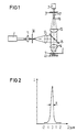
- FIG. 1 shows a procedure which has already been tried and tested in the three-dimensional measurement of structured surfaces. This is based on the confocal principle.
- a punctiform light source is formed, for example by means of a pinhole or, as in this case by a laser 1, imaged on the object.
- the backscattered light is in turn imaged on an almost point-like detector.
- Maximum light intensity strikes the detector only in the event that the object and detector planes are actually in the focal point, that is to say are confocal.
- the punctiform design of each of the two components mentioned occurs through the respective upstream connection of a confocal diaphragm 30, 31.
- the laser 1 with the optics 11 and the diaphragm 30 can be regarded as a point light source.
- the punctiform detector consists of the diaphragm 31 and the actual detector 2, for example a photodiode.
- a confocal constellation is represented by the beam path of the focused beam 16.
- the object 4 lies in the focal plane with respect to the optics 14.
- FIG. 1 works with a divider mirror 15.
- the objective, here the optics 14, is designed so that there are no differences in the aperture of the measuring beam in relation to the aperture of the illuminating beam are recognizable.
- FIG. 2 shows the course of the intensity I of the detected light as a function of the height value Z.
- An evaluation criterion represents the full half-value width H. This is understood to mean the range of the height value Z which corresponds to a drop in the intensity I to half the maximum value.
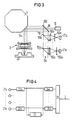
- FIG. 3 shows a structure according to the invention, according to a modified confocal principle.
- the multi-stage confocal structure which is achieved by splitting the measuring beam 19 into a plurality of individual beams, each with an optical system 152a-n, an aperture 153a-n and a photodetector 21a-n.
- the illuminating beam 18 is generated by a laser 10 and directed onto a rotating polygon mirror 5 by a coupling mirror 150 provided with a bore. This reflects the illuminating beam 18 in the direction of the surface of the object 40.
- a scanning objective 6 which guides the illuminating beam 18 and measuring beam 19 in both directions simultaneously.
- the numerical aperture of the illuminating beam 18 is significantly smaller than the numerical aperture of the measuring beam 19.
- the measuring beam 19 guided over the scanning objective is in turn guided back to the coupling-out mirror 150 via the rotating polygon mirror. Subsequently, the measuring beam 19 is split in a beam splitting unit 154.
- the beam splitting unit 154 can consist of splitter mirrors 151a-n. To reduce the mechanical complexity, however, it is also possible to use a diffraction grating or a computer-generated hologram. The high expenditure for the production of a hologram can be due to the associated essential advantages are balanced.
- the intensity distribution of the diffracted light can be influenced in a predetermined manner depending on the requirement by an appropriately designed hologram.
- electronic compensation ensures a uniform distribution of the intensities of the divided measuring beams 19.
- FIG. 4 shows evaluation electronics which process different light intensities in accordance with the existing plurality of photodetectors 21a-n.
- Each detector represents a height value within the depth of focus T and the electronics find out the one with the highest power. This is achieved by means of a threshold, the height of which corresponds to a certain percentage value of the sum of all intensity values. If several signals exceed the threshold value, the corresponding height values Z must be averaged.
- the evaluation electronics receives the corresponding signals from the photodetectors 21a-n via amplifiers 22a-n, adds them in the summer 23 and compares the individual values in comparators 24a-n with the sum.
- the encoder 25 supplies the desired height value Z. In order to achieve a high pixel processing speed, this parallel processing mode is necessary. Sample / hold amplifiers, for example, can be used as amplifiers 22a-n.
- FIG. 5 schematically shows the focus area of the illumination beam 18. This has a waist diameter D1 at its waist.
- the depth of focus T is defined so that it corresponds to the length of the illuminating beam in the focus area, between which the beam diameter D2 of the illuminating beam 18 has increased in both directions to ⁇ 2 times D1.
- the maximum height scanning range is predetermined by the depth of focus T. However, it can be changed by changing the scan lens 6. Another possibility that does not conform to the increase in the data rate would be the mechanical movement of the object.
- a sensor after The confocal principle according to FIG. 1 is therefore optically sufficiently good, but too slow for the applications required today.
- the large depth of focus in the illumination due to the small diameter of the illumination beam 18 on the object 40 is converted into a relatively small depth of focus in the image. Due to the division into individual measuring beams 19, the resolution or the depth of focus is divided into small depth-of-field areas.
- the enlargement of the aperture means a higher resolution and the enlargement of the focal length brings with it a larger height measuring range corresponding to the greater depth of focus.
- a resolution of 20 »m can be achieved, for example, with an aperture ratio of measuring and illuminating beam 18, 19 of 25 with a height measurement of 0.5 mm.
- the resolution can be increased by suitable interpolation between the height levels.
- a change in the height measuring range can be achieved in a simple manner by changing the scanning objective 6.
- the slow lateral displacement of the object 40 in one can be done by an optical distance sensor according to FIG Directions are avoided.
- the use of an additional galvanometer mirror could completely eliminate the lateral displacement of the object 40.
- the second lateral scanning direction is operated by scanning using the illumination beam 18.
- the height values Z are determined for each individual measuring point on the surface of the object 40 via the optical distance sensor. In this way, pixel rates of 2 MHz can be achieved.
- the data rate or scan speed depends on the polygon mirror configuration.
- An embodiment of an optical distance sensor contains the following technical data, for example:
- the pixel data rate for the above-mentioned data is 4.2 MHz, which must be processed by the sensor electronics.
- the effective factor of the polygon mirror of 0.5 results in an effective pixel data rate of 2.1 MHz.
- the sensor electronics connected to an optical distance sensor according to FIG. 4 also contains the photodetectors 21a-n.
- the photodiodes and amplifiers 22a-n used here should have a very large dynamic range with a short rise time, around the extremely strong intensity fluctuations caused by the surface of the object 40 to be able to record or compensate. To avoid amplifier overloads, amplifiers with a non-linear gain characteristic can therefore be used.
- reflecting surfaces can also be checked with a distance sensor according to the invention, it is also important that the intensity control of the illumination beam 18 can be dispensed with.
Landscapes
- Physics & Mathematics (AREA)
- General Physics & Mathematics (AREA)
- Length Measuring Devices By Optical Means (AREA)
- Microscoopes, Condenser (AREA)
- Measurement Of Optical Distance (AREA)
Abstract
Claims (15)
- Détecteur optique de distance opérant selon le principe de la formation d'images optiques confocales pour la détermination de valeurs de hauteur et pour la mesure tridimensionnelle de surfaces, notamment pour l'inspection de modules électroniques plats, comportant- une source de lumière ponctuelle (1.10), dont l'image est formée sur la surface à mesurer,- une unité (5) de déviation du faisceau pour réaliser le balayage pas-à-pas de la surface,- un objectif de balayage (6), qui guide le faisceau d'éclairement (18) et le faisceau de mesure (19), et- un photodétecteur (2) disposé d'une manière confocale par rapport à la source de lumière ponctuelle,caractérisé par- un faisceau d'éclairement (18), qui, par rapport au faisceau de mesure (19), possède un diamètre nettement plus faible dans les pupilles de l'objectif de balayage (6),- des diamètres approximativement identiques pour le faisceau d'éclairement (18) et le faisceau de mesure (19) à l'emplacement de mesure sur la surface de l'objet, le faisceau d'éclairement (18) possédant une profondeur de focalisation (T) nettement supérieure à celle du faisceau de mesure (19),- une unité de division de faisceau (154) servant à diviser le faisceau de mesure (19) et en arrière de laquelle sont disposés, respectivement dans la direction des faisceaux de mesure divisés (19), un système optique (152a-n) et un photodétecteur de forme approximativement ponctuelle, les photodétecteurs étant disposés de façon décalée dans la direction des faisceaux de mesure divisés (19), pour établir une distinction entre des valeurs de hauteur dans les limites de la profondeur de foyer (T) du faisceau d'éclairement (18), et l'échelon respectif de hauteur pouvant être identifié par le photodétecteur possédant l'intensité lumineuse maximale,- l'image des diamètres des photodétecteurs de forme approximativement ponctuelle, qui sont agencés de telle sorte que l'image des diamètres, qui varient avec la hauteur, du faisceau d'éclairement (18) est formée, dans les limites de la profondeur du foyer (T), de façon précise sur les photodétecteurs associés.
- Détecteur optique de distance suivant la revendication 1, caractérisé par le fait que l'unité de division de faisceau (154) est formée par une multiplicité de miroirs diviseurs (151a-n), qui sont disposés les uns derrière les autres dans le faisceau de mesure (19).
- Détecteur optique de distance suivant la revendication 1, caractérisé par le fait que pour la division du faisceau de mesure (19) il est prévu un seul élément de diffraction de la lumière, qui divise le faisceau de mesure (19) en une multiplicité de directions définies, les photodétecteurs de forme ponctuelle étant disposés de manière décalée dans la direction des faisceaux de mesure divisés (19) pour distinguer des valeurs de hauteur dans les limites de la profondeur de foyer (T) du faisceau d'éclairement (18) et l'échelon respectif de hauteur pouvant être identifié par le photodétecteur présentant l'intensité lumineuse maximale.
- Détecteur optique de distance suivant la revendication 3, caractérisé par le fait qu'un seul système optique est disposé en avant ou en arrière de l'élément de diffraction de la lumière, à la place du système optique (152a-n).
- Détecteur optique de distance suivant l'une des revendications précédentes, caractérisé par le fait que l'agencement de forme approximativement ponctuelle des photodétecteurs (21a-n) est obtenu grâce à l'utilisation d'un diaphragme (153a-n) disposé en avant des photodétecteurs.
- Détecteur optique de distance suivant la revendication 5, prise en référence à la revendication 1 ou 2, caractérisé par le fait que l'objectif de balayage (6) est conçu pour plusieurs longueurs d'onde lumineuses de telle sorte que les zones de profondeur de champ de différentes couleurs se succèdent en série et que les intensités en arrière du diaphragme (153a-n) peuvent être enregistrées par plusieurs photodétecteurs sensibles aux couleurs, en fonction de la couleur.
- Détecteur optique de distance suivant l'une des revendications précédentes, caractérisé par le fait que la source de lumière ponctuelle est constituée par un laser (10).
- Détecteur optique de distance suivant l'une des revendications précédentes, caractérisé par le fait que l'unité de déviation du faisceau est formée par un miroir polygonal rotatif (5).
- Détecteur optique de distance suivant l'une des revendications précédentes, caractérisé par le fait que pour la séparation du faisceau d'éclairement (18) et du faisceau de mesure, on utilise un miroir de découplage (150), qui possède un perçage central.
- Détecteur optique de distance suivant l'une des revendications précédentes, caractérisé par le fait que le rapport entre les angles d'ouverture du faisceau de mesure (19) et du faisceau d'éclairement (18) à l'emplacement de mesure est égal à au moins 2:1.
- Détecteur optique de distance suivant l'une des revendications précédentes, caractérisé par le fait que l'objectif de balayage (6) possède un agencement télécentrique.
- Détecteur optique de distance suivant l'une des revendications précédentes, caractérisé par le fait que pour modifier la résolution tridimensionnelle et la gamme de mesure, on peut modifier la distance focale de l'objectif de balayage (6) ou remplacer ce dernier par un autre.
- Détecteur optique de distance suivant l'une des revendications précédentes, caractérisé par le fait qu'il est prévu une unité de compensation électronique, qui compense des distributions non uniformes d'intensité des faisceaux partiels du faisceau de mesure (19) sur les différents photodétecteurs.
- Détecteur optique de distance suivant l'une des revendications précédentes, caractérisé par le fait que les amplificateurs électroniques (22a à n) possèdent, en fonction des photodétecteurs (21a à n), une courbe d'amplification caractéristique non linéaire, afin d'éviter des surmodulations.
- Détecteur optique de distance suivant l'une des revendications précédentes, caractérisé par le fait que le détecteur de distance est incliné par rapport à la normale à la surface de l'objet de manière à permettre l'observation d'objets tridmensionnels, obliquement à partir du haut.
Priority Applications (1)
| Application Number | Priority Date | Filing Date | Title |
|---|---|---|---|
| EP92923049A EP0615607B1 (fr) | 1991-12-04 | 1992-11-03 | Appareil optique pour la mesure des distances |
Applications Claiming Priority (4)
| Application Number | Priority Date | Filing Date | Title |
|---|---|---|---|
| EP91120863 | 1991-12-04 | ||
| EP91120863 | 1991-12-04 | ||
| PCT/EP1992/002522 WO1993011403A1 (fr) | 1991-12-04 | 1992-11-03 | Appareil optique pour la mesure des distances |
| EP92923049A EP0615607B1 (fr) | 1991-12-04 | 1992-11-03 | Appareil optique pour la mesure des distances |
Publications (2)
| Publication Number | Publication Date |
|---|---|
| EP0615607A1 EP0615607A1 (fr) | 1994-09-21 |
| EP0615607B1 true EP0615607B1 (fr) | 1995-05-24 |
Family
ID=8207405
Family Applications (1)
| Application Number | Title | Priority Date | Filing Date |
|---|---|---|---|
| EP92923049A Expired - Lifetime EP0615607B1 (fr) | 1991-12-04 | 1992-11-03 | Appareil optique pour la mesure des distances |
Country Status (5)
| Country | Link |
|---|---|
| US (1) | US5448359A (fr) |
| EP (1) | EP0615607B1 (fr) |
| JP (1) | JP2511391B2 (fr) |
| DE (1) | DE59202372D1 (fr) |
| WO (1) | WO1993011403A1 (fr) |
Cited By (4)
| Publication number | Priority date | Publication date | Assignee | Title |
|---|---|---|---|---|
| DE19524022A1 (de) * | 1995-06-30 | 1997-01-09 | Siemens Ag | Optischer Abstandssensor |
| US5991040A (en) * | 1995-06-30 | 1999-11-23 | Siemens Aktiengesellschaft | Optical distance sensor |
| DE10350716B3 (de) * | 2003-10-30 | 2005-07-14 | Minebea Co., Ltd. | Verfahren zur Messung des Füllstandes einer Flüssigkeit in einem Hohlraum mit sub-mm breiter Öffnung |
| DE102007011877A1 (de) * | 2007-03-13 | 2008-09-18 | Eppendorf Ag | Optisches Sensorsystem an einer Vorrichtung zur Behandlung von Flüssigkeiten |
Families Citing this family (45)
| Publication number | Priority date | Publication date | Assignee | Title |
|---|---|---|---|---|
| EP0623804A3 (fr) | 1993-05-06 | 1995-02-01 | Philips Electronics Nv | Dispositif pour la mesure optique de la hauteur d'une surface. |
| DE4431922A1 (de) * | 1994-09-08 | 1996-05-23 | Krupp Ag Hoesch Krupp | Lichtschnitt-Triangulations-Verfahren und Vorrichtung zur on-line-Vermessung von bewegten Profilen |
| WO1996010728A1 (fr) * | 1994-09-30 | 1996-04-11 | Komatsu Ltd. | Dispositif optique confocal |
| WO1997043611A1 (fr) * | 1996-05-16 | 1997-11-20 | Affymetrix, Inc. | Systemes et procedes de detection de produits marques |
| DE19640496A1 (de) * | 1996-10-01 | 1998-04-02 | Leica Lasertechnik | Verfahren zur Oberflächenvermessung mittels Konfokalmikroskopie |
| US6167173A (en) * | 1997-01-27 | 2000-12-26 | Carl Zeiss Jena Gmbh | Laser scanning microscope |
| DE19709992C1 (de) * | 1997-03-11 | 1998-10-01 | Betr Forsch Inst Angew Forsch | Verfahren zum Messen der Oberflächengeometrie von Warmband |
| DE19717488C2 (de) * | 1997-04-25 | 2003-05-15 | Baumer Optronic Gmbh | Vorrichtung zur Inspektion der Oberfläche von Objekten |
| US5917600A (en) * | 1997-06-18 | 1999-06-29 | Cybo Robots, Inc | Displacement sensor |
| DE69824387T2 (de) * | 1998-02-26 | 2005-08-04 | Agilent Technologies Inc., A Delaware Corp., Palo Alto | Bestimmung von topographischen Werten |
| US6366357B1 (en) * | 1998-03-05 | 2002-04-02 | General Scanning, Inc. | Method and system for high speed measuring of microscopic targets |
| US6098031A (en) * | 1998-03-05 | 2000-08-01 | Gsi Lumonics, Inc. | Versatile method and system for high speed, 3D imaging of microscopic targets |
| IL125659A (en) | 1998-08-05 | 2002-09-12 | Cadent Ltd | Method and device for three-dimensional simulation of a structure |
| US6313915B1 (en) * | 1998-08-27 | 2001-11-06 | Murata Manufacturing Co., Ltd. | Displacement measuring method and apparatus |
| WO2000070331A1 (fr) * | 1999-05-14 | 2000-11-23 | Gunther Krieg | Procede et dispositif pour detecter et differencier des contaminations et des matieres, ainsi que differentes teintes dans des particules solides |
| US6731383B2 (en) | 2000-09-12 | 2004-05-04 | August Technology Corp. | Confocal 3D inspection system and process |
| US20020145734A1 (en) * | 2001-02-09 | 2002-10-10 | Cory Watkins | Confocal 3D inspection system and process |
| US20020148984A1 (en) * | 2001-02-09 | 2002-10-17 | Cory Watkins | Confocal 3D inspection system and process |
| US6870609B2 (en) * | 2001-02-09 | 2005-03-22 | August Technology Corp. | Confocal 3D inspection system and process |
| DE10125885B4 (de) * | 2001-05-28 | 2004-09-16 | Siemens Ag | Sensorvorrichtung zur schnellen optischen Abstandsmessung nach dem konfokalen optischen Abbildungsprinzip |
| US6882415B1 (en) | 2001-07-16 | 2005-04-19 | August Technology Corp. | Confocal 3D inspection system and process |
| JP2004538454A (ja) * | 2001-07-16 | 2004-12-24 | オーガスト テクノロジー コーポレイション | 共焦3d検査システムおよびプロセス |
| US6970287B1 (en) | 2001-07-16 | 2005-11-29 | August Technology Corp. | Confocal 3D inspection system and process |
| US6917421B1 (en) | 2001-10-12 | 2005-07-12 | Kla-Tencor Technologies Corp. | Systems and methods for multi-dimensional inspection and/or metrology of a specimen |
| US6693658B2 (en) * | 2001-12-20 | 2004-02-17 | Kabushiki Kaisha Toshiba | Light beam scanning apparatus |
| US6750974B2 (en) * | 2002-04-02 | 2004-06-15 | Gsi Lumonics Corporation | Method and system for 3D imaging of target regions |
| DE10242374A1 (de) * | 2002-09-12 | 2004-04-01 | Siemens Ag | Konfokaler Abstandssensor |
| JP4209709B2 (ja) * | 2003-03-20 | 2009-01-14 | 株式会社キーエンス | 変位計 |
| NO320062B1 (no) * | 2003-11-19 | 2005-10-17 | New Interaction Devices And Te | Anordning til a detektere naerhet mellom et forste objekt (malobjekt) og et annet objekt (referanseobjekt), samt tegne-, skrive- og/eller pekeredskap for datapresentasjon etc. |
| CN100489752C (zh) * | 2004-02-09 | 2009-05-20 | 皇家飞利浦电子股份有限公司 | 基于多普勒频移和激光自混和的光学输入设备 |
| WO2005083399A1 (fr) | 2004-02-27 | 2005-09-09 | Technical Co., Ltd | Système optique d’observation simultanée multidirectionnelle, lecteur d’image, procédé de lecture d’image, corps composite à système optique d’observation simultanée multidirectionnelle |
| US7323705B2 (en) | 2004-06-29 | 2008-01-29 | Applera Corporation | Liquid level measurement |
| US20060232790A1 (en) * | 2005-04-18 | 2006-10-19 | Lee Chase | Confocal measurement method and apparatus in a paper machine |
| NO329603B1 (no) * | 2007-11-22 | 2010-11-22 | Integrated Optoelectronics As | Fremgangsmate og system for maling og bestemmelse / gjenkjenning av ulike materialer |
| US8159156B2 (en) * | 2009-08-10 | 2012-04-17 | Redwood Systems, Inc. | Lighting systems and methods of auto-commissioning |
| NO336546B1 (no) * | 2010-09-24 | 2015-09-21 | Tomra Sorting As | Apparat og fremgangsmåte for inspeksjon av materie |
| US8759734B2 (en) | 2012-02-23 | 2014-06-24 | Redwood Systems, Inc. | Directional sensors for auto-commissioning lighting systems |
| KR101614061B1 (ko) * | 2012-03-29 | 2016-04-20 | 주식회사 고영테크놀러지 | 조인트 검사 장치 |
| JP6119232B2 (ja) * | 2012-12-19 | 2017-04-26 | 株式会社ソシオネクスト | 距離測定装置、距離測定方法 |
| US9713232B2 (en) * | 2013-09-03 | 2017-07-18 | Philips Lighting Holding B.V. | Lighting commissioning |
| RU2650856C2 (ru) * | 2016-08-29 | 2018-04-17 | Российская Федерация, от имени которой выступает Министерство обороны Российской Федерации | Устройство для определения местоположения источника электромагнитного излучения |
| JP6548754B2 (ja) * | 2018-01-09 | 2019-07-24 | キヤノン株式会社 | 光学装置、それを備える車載システム及び移動装置 |
| JP7365266B2 (ja) * | 2020-02-28 | 2023-10-19 | レーザーテック株式会社 | 測定装置及び測定方法 |
| WO2022087314A1 (fr) * | 2020-10-22 | 2022-04-28 | Nikon Corporation | Mesure de la position d'une cuve d'immersion dans la fabrication additive |
| CN120212889A (zh) * | 2025-04-16 | 2025-06-27 | 致微(苏州)光学技术有限公司 | 镜片厚度的测量装置及测量方法 |
Family Cites Families (8)
| Publication number | Priority date | Publication date | Assignee | Title |
|---|---|---|---|---|
| JPS52107855A (en) * | 1976-03-05 | 1977-09-09 | Koito Mfg Co Ltd | Noncontact type position detector |
| SU868341A1 (ru) * | 1980-01-31 | 1981-09-30 | Завод-Втуз При Московском Трижды Ордена Ленина,Ордена Октябрьской Революции И Ордена Трудового Красного Знамени Автомобильном Заводе Им. И.А.Лихачева | Устройство дл бесконтактного измерени рассто ний |
| JPS5935163A (ja) * | 1982-08-23 | 1984-02-25 | Mitsubishi Electric Corp | 衝突防止警報装置 |
| IT1198660B (it) * | 1983-08-02 | 1988-12-21 | Ottica Ist Naz | Profilometro ottico multifocale per dispersione |
| JPS61169708A (ja) * | 1985-01-22 | 1986-07-31 | Fujitsu Ltd | パタ−ン検知方法とその装置 |
| JPS61259115A (ja) * | 1985-05-13 | 1986-11-17 | Japan Aviation Electronics Ind Ltd | 光フアイバセンサ |
| US4798469A (en) * | 1985-10-02 | 1989-01-17 | Burke Victor B | Noncontact gage system utilizing reflected light |
| CH671828A5 (fr) * | 1987-06-26 | 1989-09-29 | Battelle Memorial Institute |
-
1992
- 1992-08-24 JP JP4248620A patent/JP2511391B2/ja not_active Expired - Fee Related
- 1992-11-03 WO PCT/EP1992/002522 patent/WO1993011403A1/fr not_active Ceased
- 1992-11-03 DE DE59202372T patent/DE59202372D1/de not_active Expired - Fee Related
- 1992-11-03 US US08/244,622 patent/US5448359A/en not_active Expired - Lifetime
- 1992-11-03 EP EP92923049A patent/EP0615607B1/fr not_active Expired - Lifetime
Cited By (4)
| Publication number | Priority date | Publication date | Assignee | Title |
|---|---|---|---|---|
| DE19524022A1 (de) * | 1995-06-30 | 1997-01-09 | Siemens Ag | Optischer Abstandssensor |
| US5991040A (en) * | 1995-06-30 | 1999-11-23 | Siemens Aktiengesellschaft | Optical distance sensor |
| DE10350716B3 (de) * | 2003-10-30 | 2005-07-14 | Minebea Co., Ltd. | Verfahren zur Messung des Füllstandes einer Flüssigkeit in einem Hohlraum mit sub-mm breiter Öffnung |
| DE102007011877A1 (de) * | 2007-03-13 | 2008-09-18 | Eppendorf Ag | Optisches Sensorsystem an einer Vorrichtung zur Behandlung von Flüssigkeiten |
Also Published As
| Publication number | Publication date |
|---|---|
| DE59202372D1 (de) | 1995-06-29 |
| EP0615607A1 (fr) | 1994-09-21 |
| JPH05240607A (ja) | 1993-09-17 |
| US5448359A (en) | 1995-09-05 |
| JP2511391B2 (ja) | 1996-06-26 |
| WO1993011403A1 (fr) | 1993-06-10 |
Similar Documents
| Publication | Publication Date | Title |
|---|---|---|
| EP0615607B1 (fr) | Appareil optique pour la mesure des distances | |
| DE69904304T2 (de) | Vielseitiges verfahren und vorrichtung zur schnellen, dreidimensionalen abbildung mikroskopischer ziele | |
| DE3123703C2 (fr) | ||
| EP0835423B1 (fr) | Capteur optique de distance | |
| DE10242373B4 (de) | Konfokaler Abstandssensor | |
| DE10242374A1 (de) | Konfokaler Abstandssensor | |
| DE2802416A1 (de) | Optische vorrichtung | |
| EP1610088A1 (fr) | Dispositif de mesure optique d'un objet | |
| EP0085868B1 (fr) | Dispositif de contrôle viruel de qualité automatique | |
| DE112015000627T5 (de) | Mikrospektroskopische Vorrichtung | |
| DE60204495T2 (de) | Linsenmesser zur Messung der Eigenschaft eines Brillenglases oder einer Kontaktlinse | |
| DE102017001758A1 (de) | Messverfahren und messprogramm | |
| DE102011083421A1 (de) | Verfahren und Vorrichtung zum Vermessen homogen reflektierender Oberflächen | |
| DE4434699C2 (de) | Anordnung zur Prüfung durchsichtiger oder spiegelnder Objekte | |
| DE19608468C2 (de) | Optischer Abstandssensor | |
| EP0893685A2 (fr) | Dispositif et procédé de détection optique de la distorsion d'une surface | |
| DE69010318T2 (de) | Abtastanordnung zum Abtasten einer Oberfläche entlang einer Linie mittels optischer Strahlung. | |
| DE4229313A1 (de) | Verfahren und Vorrichtung zur hochgenauen Abstandsmessung von Oberflächen | |
| DE102018210927A1 (de) | Laserbestrahlungsoberflächeninspektionsvorrichtung für ein Werkstück und Vorrichtung zur Erfassung reflektierter Strahlen für eine Laserbearbeigungsmaschine | |
| DE60121746T2 (de) | Bildaufnahmeeinrichtung | |
| EP2191229B1 (fr) | Procédé pour déterminer une arête d'un objet sur lequel doit être réalisée une mesure optique et appareil de mesure de coordonnées | |
| DE102017210098B4 (de) | Scanvorrichtung mit einer Scankopfvorrichtung zum Reflektieren oder Transmittieren von Strahlen für einen Scanner sowie Verfahren zum Reflektieren oder Transmittieren von Strahlen für einen Scanner | |
| EP4010145A1 (fr) | Procédé d'analyse de la surface d'une pièce dans le cadre d'un processus d'usinage laser et dispositif d'analyse destiné à analyser la surface d'une pièce | |
| DE3641863A1 (de) | Oberflaechenpruefvorrichtung | |
| DE3703504A1 (de) | Verfahren und vorrichtung zur bestimmung der oberflaechenrauhigkeit und/oder der oberflaechenstruktur von gegenstaenden |
Legal Events
| Date | Code | Title | Description |
|---|---|---|---|
| PUAI | Public reference made under article 153(3) epc to a published international application that has entered the european phase |
Free format text: ORIGINAL CODE: 0009012 |
|
| 17P | Request for examination filed |
Effective date: 19940526 |
|
| AK | Designated contracting states |
Kind code of ref document: A1 Designated state(s): DE FR GB IT NL |
|
| 17Q | First examination report despatched |
Effective date: 19941017 |
|
| GRAA | (expected) grant |
Free format text: ORIGINAL CODE: 0009210 |
|
| AK | Designated contracting states |
Kind code of ref document: B1 Designated state(s): DE FR GB IT NL |
|
| REF | Corresponds to: |
Ref document number: 59202372 Country of ref document: DE Date of ref document: 19950629 |
|
| ITF | It: translation for a ep patent filed | ||
| ET | Fr: translation filed | ||
| GBT | Gb: translation of ep patent filed (gb section 77(6)(a)/1977) |
Effective date: 19950807 |
|
| PLBE | No opposition filed within time limit |
Free format text: ORIGINAL CODE: 0009261 |
|
| STAA | Information on the status of an ep patent application or granted ep patent |
Free format text: STATUS: NO OPPOSITION FILED WITHIN TIME LIMIT |
|
| 26N | No opposition filed | ||
| REG | Reference to a national code |
Ref country code: GB Ref legal event code: IF02 |
|
| PGFP | Annual fee paid to national office [announced via postgrant information from national office to epo] |
Ref country code: GB Payment date: 20031104 Year of fee payment: 12 |
|
| PGFP | Annual fee paid to national office [announced via postgrant information from national office to epo] |
Ref country code: NL Payment date: 20031105 Year of fee payment: 12 |
|
| PGFP | Annual fee paid to national office [announced via postgrant information from national office to epo] |
Ref country code: FR Payment date: 20031127 Year of fee payment: 12 |
|
| PG25 | Lapsed in a contracting state [announced via postgrant information from national office to epo] |
Ref country code: GB Free format text: LAPSE BECAUSE OF NON-PAYMENT OF DUE FEES Effective date: 20041103 |
|
| PG25 | Lapsed in a contracting state [announced via postgrant information from national office to epo] |
Ref country code: NL Free format text: LAPSE BECAUSE OF NON-PAYMENT OF DUE FEES Effective date: 20050601 |
|
| GBPC | Gb: european patent ceased through non-payment of renewal fee |
Effective date: 20041103 |
|
| PG25 | Lapsed in a contracting state [announced via postgrant information from national office to epo] |
Ref country code: FR Free format text: LAPSE BECAUSE OF NON-PAYMENT OF DUE FEES Effective date: 20050729 |
|
| NLV4 | Nl: lapsed or anulled due to non-payment of the annual fee |
Effective date: 20050601 |
|
| REG | Reference to a national code |
Ref country code: FR Ref legal event code: ST |
|
| PG25 | Lapsed in a contracting state [announced via postgrant information from national office to epo] |
Ref country code: IT Free format text: LAPSE BECAUSE OF NON-PAYMENT OF DUE FEES;WARNING: LAPSES OF ITALIAN PATENTS WITH EFFECTIVE DATE BEFORE 2007 MAY HAVE OCCURRED AT ANY TIME BEFORE 2007. THE CORRECT EFFECTIVE DATE MAY BE DIFFERENT FROM THE ONE RECORDED. Effective date: 20051103 |
|
| PGFP | Annual fee paid to national office [announced via postgrant information from national office to epo] |
Ref country code: DE Payment date: 20080121 Year of fee payment: 16 |
|
| PG25 | Lapsed in a contracting state [announced via postgrant information from national office to epo] |
Ref country code: DE Free format text: LAPSE BECAUSE OF NON-PAYMENT OF DUE FEES Effective date: 20090603 |