EP0615739B1 - Dispositif en combination avec et pour orienter des corps et des couvercles de capsules en gélatine dure - Google Patents
Dispositif en combination avec et pour orienter des corps et des couvercles de capsules en gélatine dure Download PDFInfo
- Publication number
- EP0615739B1 EP0615739B1 EP94101529A EP94101529A EP0615739B1 EP 0615739 B1 EP0615739 B1 EP 0615739B1 EP 94101529 A EP94101529 A EP 94101529A EP 94101529 A EP94101529 A EP 94101529A EP 0615739 B1 EP0615739 B1 EP 0615739B1
- Authority
- EP
- European Patent Office
- Prior art keywords
- cap
- base
- caps
- pusher
- bases
- Prior art date
- Legal status (The legal status is an assumption and is not a legal conclusion. Google has not performed a legal analysis and makes no representation as to the accuracy of the status listed.)
- Expired - Lifetime
Links
Images



Classifications
-
- A—HUMAN NECESSITIES
- A61—MEDICAL OR VETERINARY SCIENCE; HYGIENE
- A61J—CONTAINERS SPECIALLY ADAPTED FOR MEDICAL OR PHARMACEUTICAL PURPOSES; DEVICES OR METHODS SPECIALLY ADAPTED FOR BRINGING PHARMACEUTICAL PRODUCTS INTO PARTICULAR PHYSICAL OR ADMINISTERING FORMS; DEVICES FOR ADMINISTERING FOOD OR MEDICINES ORALLY; BABY COMFORTERS; DEVICES FOR RECEIVING SPITTLE
- A61J3/00—Devices or methods specially adapted for bringing pharmaceutical products into particular physical or administering forms
- A61J3/07—Devices or methods specially adapted for bringing pharmaceutical products into particular physical or administering forms into the form of capsules or similar small containers for oral use
- A61J3/071—Devices or methods specially adapted for bringing pharmaceutical products into particular physical or administering forms into the form of capsules or similar small containers for oral use into the form of telescopically engaged two-piece capsules
- A61J3/074—Filling capsules; Related operations
-
- Y—GENERAL TAGGING OF NEW TECHNOLOGICAL DEVELOPMENTS; GENERAL TAGGING OF CROSS-SECTIONAL TECHNOLOGIES SPANNING OVER SEVERAL SECTIONS OF THE IPC; TECHNICAL SUBJECTS COVERED BY FORMER USPC CROSS-REFERENCE ART COLLECTIONS [XRACs] AND DIGESTS
- Y10—TECHNICAL SUBJECTS COVERED BY FORMER USPC
- Y10S—TECHNICAL SUBJECTS COVERED BY FORMER USPC CROSS-REFERENCE ART COLLECTIONS [XRACs] AND DIGESTS
- Y10S53/00—Package making
- Y10S53/90—Capsules
Definitions
- the invention relates to a device in combination with and for the assembly of the bases and caps of hard gelatin capsules in pre-sealed form.
- the device according to the invention can be used in combination with hard gelatin capsules of conventional construction or with capsules of special construction and/or shape, for example those of the SCHERER type.
- the device according to the invention is, on the contrary, intended to solve a problem which is new in the field of capsules for medicinal use, consisting in the fact that the caps and bases of the capsules which are initially separated from each other and are kept loose in two distinct magazines, since the two enclosing elements of the capsules, especially in the case of the aforesaid special capsules, undergo different operations in the process of their manufacture, such that the said enclosing elements cannot be advantageously pre-assembled using the conventional methods, are picked up from said magazines, are correctly oriented and are thereafter coupled, so as to form pre-closed empty caps.
- the device according to the invention may therefore be used by the manufacturers of special capsules, to enable them to supply the capsules in pre-sealed form to those industries which will carry out the filling of the said capsules with conventional methods and machines, or may be used in combination with a machine for filling and sealing the capsules, in which the bases and caps of the capsules are fed loose in corresponding magazines.
- the device will orientate the bases of the capsules with the opening facing upwards and will insert each base into a supporting socket, while the caps will be orientated with the opening downwards and will be inserted into a corresponding supporting socket.
- the sockets containing the caps are located at a higher level than those containing the bases and are preferably disposed with their axes vertical.
- the sockets containing the bases and the caps are carried by horizontally movable means by means of which the said sockets may be moved out of alignment with each other to permit the operation of the means of feeding the two separate parts of the capsule to the sockets and/or to permit the insertion of doses of a medicinal product and of any plugs or diaphragms into the bases for any known use, or may be aligned axially with each other to enable the base to be fed to the lower socket, with the empty upper socket into which the cap is subsequently to be inserted passing across it, and/or to initiate the final phase of sealing the capsule, with the raising of the empty or full base, the insertion of the base into the cap which is located above it and is temporarily retained by a suitable check piece and with the final raising and lateral expulsion of the sealed capsule.
- One object of the present invention is to provide a device for orientating and feeding the bases and caps of the capsules which is of simplified construction and high technological reliability, and may be combined with a high-output enclosing machine of the carousel type.
- the bases and caps are fed one at a time to a corresponding vertical seat which contains them with a certain amount of play, and in which they may be orientated with the opening upwards or downwards.
- This seat is disposed in the intermediate part of a horizontal channel, the section of which up-line from the said seat is engaged slidably by an orientating pusher with a point facing the aforesaid seat.
- the section of the said horizontal channel disposed downline from the seat has a width slightly less than that of the outer area of greater width of the cap or base, so that, when the said pusher operates and its point acts on the intermediate part of the base or cap, the rounded end of the component, which has a greater resistance to crushing, encounters a greater sliding friction in the channel, so that, under the action of the point of the pusher, the base or cap of the capsule is orientated with the opening forward and in this condition reaches the terminal part of the orientation channel, with a substantially horizontal disposition.
- This channel follows a second vertical and ascending channel, whose width is equal to that of the first channel and which terminates in a suitably wider lower section.
- a second pusher comes into operation and, in the case of the base, acts on it with a flat and horizontal or suitably inclined end, so that the base reaches the wider terminal part of the ascending channel where it is picked up by suction by its rounded end and inserted into the corresponding supporting socket, with a vertical disposition and with the opening upwards.
- the second pusher which acts on the caps, is instead provided with a point which acts on the intermediate part of the said cap and causes its open end to rotate downwards.
- the cap reaches the wider terminal part of the second channel with a vertical disposition and with its opening downwards, and from here it is picked up by suitable suction means and inserted by them into the supporting socket lying below.
- a further object of the invention is to provide the part of the device which orientates the caps with means which stop the cap at different levels in the first seat of the device, according to the orientation in which the cap reaches the said seat, so that the cap is always correctly disposed with respect to the point of the initial orientation pusher.
- a further object is to make the said cap stop means adjustable so that it is possible to operate correctly with capsules which are of the same format but may differ slightly in their geometry and/or dimensions.
- 1 and 2 indicate known types of sockets of a carousel-type enclosing machine, with the sockets 1, for containing the base enclosing elements or bases of the capsules, disposed below the sockets 2 for containing the covering enclosing elements or caps of the capsules, at least one of the said sockets, for example the lower socket 1, being supported by known means 101 which, when so commanded, can move it from the condition of axial alignment with the upper socket to a position of non-alignment, usually in order to align the base with a mechanism for introducing a dose of medicinal product into it.
- known means 101 which, when so commanded, can move it from the condition of axial alignment with the upper socket to a position of non-alignment, usually in order to align the base with a mechanism for introducing a dose of medicinal product into it.
- the device according to the invention for orientating and feeding the bases and caps of the capsules to the sockets 1 and 2 may be disposed in any convenient way to interact with the said sockets of a carousel-type enclosing machine, to provide a high output of the said enclosing machine.
- the device in question may be fixed and the enclosing machine may be positioned in relation to it with intermittent movements, or it may be mounted on carousels with the axes parallel to those of the enclosing carousel, or it may be mounted on one or more carousels coaxial with the said enclosing carousel, to enable the latter to operate with continuous movement and consequently with a high output.
- the bases 3 of the capsules are disposed loosely in a magazine, not illustrated, into the base of which there enters and is moved cyclically with an intermittent axial motion, as indicated by the arrow 4, a tube 5 whose internal diameter is slightly greater than the maximum external diameter of the bases, so that the bases enter the tube in single file, in axial alignment and in random orientation.
- a lateral aperture 6 which allows a stop 7, pivoted for example at 8 to the tube, to act on the lower part of the file of bases disposed in the tube, to retain them during the phase in which the tube is raised.
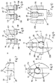
- the stop 7 is, for example, held in the blocking position by an elastic means which is not illustrated, and is, for example, provided with an extension 107 which, during the phase of lowering of the tube 5, interacts with a projection 9 which opens the stop with the consequent fall of the lowest base 3 from the tube 5 into a vertical seat 10 formed in a body 11, provided with a flared profile 110 at the top, and capable of containing the base with a small amount of play.
- elastic means which is not illustrated, and is, for example, provided with an extension 107 which, during the phase of lowering of the tube 5, interacts with a projection 9 which opens the stop with the consequent fall of the lowest base 3 from the tube 5 into a vertical seat 10 formed in a body 11, provided with a flared profile 110 at the top, and capable of containing the base with a small amount of play.
- the base 3 stops with its lower end bearing on the flat base of the said seat which is formed with a symmetrical disposition in the intermediate part of a horizontal channel 12, whose base coincides with that of the said seat and whose lateral walls are parallel to each other.
- the section of channel 112 disposed upline from the seat 10 has a width less than that of the said seat, and a pusher 13 is guided and slides longitudinally in this section, and is provided with a point 113 in the median part of the end facing the said seat 10, the said point being perpendicular to the seat 10, and having a suitably blunted terminal part 14 and having upper and lower surfaces 15 and 115 which are flat and mutually angularly equidistant with respect to the horizontal line passing through the said end 14 of the point.
- the front surfaces 16 and 116 of the pusher are disposed at 90° with respect to the said surfaces 15 and 115, or are shaped in another suitable way to provide a controlled displacement of the base (see below).
- the length of the point 113 is, for example, equal to or slightly greater than half the length of the base 3.
- the pusher 13 may be activated with a reciprocating movement, as indicated by the arrow 17, by the same means which cyclically raise and lower the tube 5, for example by rods connected to an angled lever 18, pivoted at 19, and which is made to oscillate about the said pivot by suitable means (Fig. 1).
- the part 212 of the channel 12 disposed downline from the seat 10 has a width only slightly less than the external width of the base 3 or of any wider area of the base, for example, by an amount of the order of a few hundredths or one or a few tenths of a millimetre, in accordance with the dimensions and/or the characteristics of the bases.
- the base of the channel section 212 is also aligned with the base of the seat 10 and with the base of the channel section 112.
- the channel section 212 communicates with the end of a vertical channel 312 of equal width, facing downwards, also formed in the body 11 and terminating below in a wider section 20.
- a flat pusher 21 is fixed to one side of the tube 5, and has a horizontal or suitably inclined lower edge 121 which has to be able to slide in the aforesaid vertical channel section 312, passing from the idle position indicated in Figure 1 with broken lines, where the said pusher is raised and is outside the channel 212-312, to the lowered position in which the said pusher is engaged in the channel 312 and its lower end 121 enters the wider area 20 of the said channel.
- the said socket In the phase of feeding a base 3 to a socket 1 of the enclosing machine (see Figs 1 and 2), the said socket is axially aligned and close to the upper socket 2 which is empty and is in turn close to the innermost part of the wider end 20 of the descending channel 312, while a pick-up device 22 of a known type, associated with the enclosing machine and connected to a suction source, is disposed under the socket 1.
- a base 3 enters by gravity into the seat 10 in which it may be orientated with the rounded end upwards or downwards, as illustrated in Figures 1 and 2 respectively.
- the pusher 13 is displaced towards the right in Figures 1 and 2, to pass from the position indicated with solid lines to that indicated with broken lines.
- the end 14 of the point 113 of the pusher acts approximately on the intermediate part of the base 3 disposed in the seat 10 and pushes the base into the channel section 212.
- the base 3 encounters greater friction with its lateral part nearer its closed end, since the other end section nearer the opening is more flexible and deformable because it is open. Consequently, during the displacement by the point 113, the base 3 enters the channel section 212 while rotating about its closed end, so that, regardless of the initial orientation of the base, it enters and slides in the channel 212 while becoming orientated with its open end forwards and becoming disposed under or above the point 113, depending on whether the closed end of the base faces upwards or downwards.
- the rounded end of the base bears against the front surfaces 16 - 116 of the pusher which thus displaces the base in the channel 212.
- the base 3 remains, by the effect of friction, in the next area of the channels 212-312 in a substantially horizontal position.
- the pusher 21 descends and with its lower horizontal end 121 pushes downwards the previously orientated base, which enters the wider terminal part 20 of the ascending channel 312 with its closed end above the empty socket 2, through which the effects of the suction exerted by the pick-up device 22 are manifested.
- the rounded end of the cap is immediately sucked into the socket 2 and the base 3 passes easily through the said socket, which is wider, and is stopped in the lower socket 1 with a vertical disposition and with its open end facing upwards, as illustrated in Figures 1 and 2 in broken lines.
- the pusher 21 subsequently returns to the high position and the cycle described above is repeated with another pair of empty sockets 1 and 2, while the pair of sockets mentioned previously, with the base 3 in the lower socket, are moved so that they interact, or are caused to interact, with the device for orientating and feeding the caps 23 of the capsules, which will now be described with reference to Figures 4, 5 and 6.
- the device comprises a magazine (not illustrated) which contains the caps 23 in a loose arrangement and into which there enters from below a vertical tube 25 which is movable in an axially reciprocating way as indicated by the arrow 24 and has an internal diameter such that it holds the caps 23 in single file, in axial alignment and in random orientation.
- the caps are retained in the tube by a bottom stop device 27, which passes through a lateral opening 26 in the lower part of the said tube and which is withdrawn and opened only at the moment in which the lower end of the tube is brought up to the tapered top 128 of a vertical seat 28, of circular section, whose shape and dimensions are such that they hold a cap 23 in a vertical disposition and in the same orientation as that in which it left the said tube.
- the seat 28 (see Figure 6) is formed in a body 111 and is disposed symmetrically in the intermediate part of a horizontal channel 29, whose section 129 has a width less than the diameter of the seat 28 and in which a pusher 31, provided with a point 131 facing the said seat 28, slides and is longitudinally guided with reciprocating displacement as shown by the arrow 30, in phase with the displacement of the tube 25.
- the end 32 of the point 131 is suitably blunted, while the lower flat surface 33 of the point is substantially horizontal and the upper flat surface 34 is inclined by a few degrees with respect to the subjacent surface.
- the end surfaces 35 and 36 of the pusher 31 are perpendicular to the aforesaid surfaces 33 and 34 or are otherwise conveniently shaped to provide a controlled displacement of the caps 23 (see below).
- the part 229 of the channel 29, disposed downline from the seat 28, has a width slightly less than the external diameter of the cap 23 or of the wider external area of the said cap, as described above for the bases.
- the cap 23 Following the displacement of the point of the pusher towards the right with respect to Figure 7, the cap 23 would be pushed into the channel section 229 in Figure 4, where the equatorial zone 123 of its closed and rounded end would encounter the greater resistance, so that the cap would tend to rotate about an axis perpendicular to the opposing areas of greater friction, with consequent orientation of the opening of the cap in the direction of displacement of the pusher.
- the equatorial zone 123 of the said cap would be at a short distance from the trajectory of displacement of the point 131 and immediately below the said trajectory, so that in the phase of the operation of the pusher 31 the cap disposed in this way would be crushed or orientated with its opening in a direction opposed to the direction of displacement of the pusher, or would be oriented in a random way.
- the horizontal arrow 131 indicates schematically the trajectory of displacement of the point of the pusher 31, which in the case of Figure 8 touches the cap at a point sufficiently far from and higher than the equatorial zone 123 of the said cap, with the consequent downward rotation of the said cap during the displacement in the channel section 229, with its opening orientated forwards and with the point 131 disposed in the lower part as illustrated in Figure 4 in broken lines.
- the point 131 of the pusher 31 touches the cap at a point sufficiently far from and lower than the equatorial zone 123 of the said cap, so that the said cap enters the channel section 229 while rotating upwards, becoming disposed above the said point 131, as illustrated in broken lines in Figure 5, and becoming orientated with its opening forwards, as in the preceding case.
- the aforesaid supports 37 and 137 may be made adjustable with respect to their projection and/or height within the seat 28, as indicated schematically in Figures 6, 8, and 9 by the arrows 38 and 138, to provide maximum reliability and security of operation of the device.
- the cap 23 is located in the area where the horizontal channel section 229 joins a vertical descending channel section 329, of equal width, and having at least a wider terminal section 42.
- the descending channel 329 may preferably be provided with a band 43 close to the outer longitudinal edge, and having the same width as the aforesaid terminal section 42.
- a flat pusher 44 is made integral with the tube 25, faces downwards, and has a pointed lower end 144 whose side facing the inner side of the channel 329 partially reproduces the profile of a cap 23 with a vertical disposition, as indicated by 45.
- the pusher 44 is above and outside the channel 329, as illustrated in broken lines in Figures 4 and 5.
- the pusher 44 is inside the channel 329 and its point enters the wider area 42, as illustrated in solid lines in Figures 4 and 5.
- the socket 2 of the enclosing machine is brought below and close to the channel 329, in alignment with the said channel, as illustrated in Figures 4 and 5, while the socket 1 with the base 3 has been previously brought out of alignment and conveniently removed from the socket above it, so that an axially hollow rod 46 connected to a suction circuit may be inserted axially from below into the said socket 2, with its upper end entering the wider terminal part 42 of the said channel 329.
- socket 1 While the socket 1 is in the non-aligned position illustrated in Figures 4 and 5, it is possible to insert into the base 3, disposed in the said socket, no product at all, as illustrated in Figure 14, or one or more doses of medicinal product 47 in succession as in Figure 15, or the said doses of product 47 and a plug 48 as in Figure 16, or the doses of product 47, the plug 48 and a further dose of product 49 as in Figure 17.
- the lower socket 1 with the cap 3 is re-aligned with the upper socket 2 with the cap 23 and, as illustrated in Figure 11, a check piece 50 is positioned on the cap to prevent its axial displacement, while a rod 46 is inserted in the lower socket and raises the base 3, inserting its upper end into the cap 23 and pre-sealing or sealing the capsule, as illustrated in Figure 12 and in the various suggested forms shown in Figures 14, 15, 16, and 17.
- the rod 46 then continues to rise, as shown in Figure 13, with an equal displacement or removal of the check piece 50, to extract the sealed capsule from the sockets 1 and 2 and subsequently to expel the said capsule towards collecting means disposed outside the enclosing machine, with the additional aid of an air jet schematically indicated by the arrows 51.
Landscapes
- Health & Medical Sciences (AREA)
- General Health & Medical Sciences (AREA)
- Medicinal Chemistry (AREA)
- Pharmacology & Pharmacy (AREA)
- Life Sciences & Earth Sciences (AREA)
- Animal Behavior & Ethology (AREA)
- Chemical & Material Sciences (AREA)
- Public Health (AREA)
- Veterinary Medicine (AREA)
- Medical Preparation Storing Or Oral Administration Devices (AREA)
- Feeding Of Articles To Conveyors (AREA)
- Manufacturing Of Electrical Connectors (AREA)
- Closing Of Containers (AREA)
- Sealing Of Jars (AREA)
Claims (12)
- Dispositif pris en combinaison avec les bases et les couvercles de capsules en gélatine dure et servant à l'assemblage de ces bases et couvercles de capsules en gélatine dure sous forme préscellées, en prenant ces bases et ces couvercles dans deux magasins correspondants, et en les orientant de sorte que les bases aient leur ouverture faisant face vers le haut et les couvercles leur ouverture faisant face vers le bas, comportant des moyens (5, 25) destinés à prendre les bases (3) et les couvercles (23) dans les magasins et destinés à introduire de manière cyclique une base et un couvercle dans des sièges (10, 28) verticaux, en les disposant verticalement et en les orientant au hasard, les sièges étant formés suivant une disposition symétrique dans la partie intermédiaire de canaux (12, 29) horizontaux dont les sections (112, 129) en amont ont une largeur inférieure à celle des sièges et dans lesquelles sont guidés et coulissent des poussoirs (13, 31) longitudinaux munis de pointes (113, 131) faisant face aux sièges et capables d'agir sur les parties intermédiaires des bases ou couvercles maintenus dans les sièges, les sections de canal (212, 229) disposées en aval des sièges ayant une largeur légèrement inférieure à la largeur extérieure ou à la largeur de la zone extérieure la plus large de la base ou du couvercle, de sorte que lorsque que les premiers poussoirs viennent en fonctionnement et que leurs pointes agissent sur la partie intermédiaire de la base ou du couvercle, ces éléments d'emprisonnement entrent dans les canaux (212, 229) d'orientation en aval où ils coulissent avec un frottement plus grand dans la zone proche de l'extrémité arrondie qui offre une résistance plus grande à l'écrasement, de sorte que, sous la poussée des pointes des premiers poussoirs, la base et le couvercle de la capsule prennent une orientation dans laquelle leurs ouvertures avancent vers l'avant et viennent à être disposées au-dessus ou au-dessous des pointes des poussoirs, tandis que leurs extrémités arrondies coopèrent avec les extrémités avant des poussoirs qui transfèrent la base et le couvercle dans la partie terminale des canaux d'orientation horizontaux, l'ouverture allant vers l'avant et leur position étant sensiblement horizontale, les premiers poussoirs étant alors retournés à leur position de repos, et la base et le couvercle dans la partie terminale des canaux d'orientation horizontaux étant amenés, alors qu'une autre base et un autre couvercle sont chargés dans les sièges (10, 28) devant les poussoirs, à coopérer avec des seconds poussoirs (21, 44) qui les font coulisser dans des canaux (312, 329) verticaux qui ont la même largeur que les premiers canaux à orientation horizontale, qui suivent les premiers canaux, qui sont orientés vers le bas et qui se terminent de préférence en ayant des sections (20, 42) inférieures plus larges, le second poussoir (21) opérant avec la base venant toucher son extrémité (121) sensiblement horizontale et plate, de sorte que la base descend horizontalement et entre dans la partie terminale plus large du canal descendant, sous lequel se trouve une chaussette (1) de support alignée d'attente, reliée en dessous à des moyens (22) d'aspiration, l'extrémité fermée de la base étant amenée à entrer dans la chaussette, de sorte que sous l'effet de l'aspiration, la base entre dans la chaussette de support et s'y trouve disposée verticalement, ouverture orientée vers le haut, le second poussoir étant amené à retourner à la position supérieure de repos, tandis que le premier poussoir répète le cycle décrit, exactement en phase ; le second poussoir (44) opérant avec le couvercle (23) venant toucher le couvercle dans la partie intermédiaire par sa pointe (144) d'extrémité qui fait que le couvercle tourne en ayant son ouverture dirigée vers le bas et fait en sorte que le couvercle se trouve sur le côté par rapport à la pointe, portant sur une partie (45) conformée du poussoir qui transfère verticalement le couvercle dans la partie inférieure plus large du canal ascendant, sous lequel se trouve une chaussette (2) de support alignée d'attente par laquelle passe axialement en venant du dessous une tige (36) creuse qui est reliée en dessous à des moyens d'aspiration et dont l'extrémité supérieure attend dans la partie large du canal de sorte qu'elle peut être insérée dans le couvercle et le retenir par aspiration, de sorte que, tandis que le second poussoir (44) s'élève de nouveau et que le cycle d'orientation est répété, la tige avec le couvercle revient à la position basse prise au début du cycle et insère le couvercle dans la chaussette de support, la position étant verticale et l'ouverture faisant face vers le bas, toute dose de produit médicinal (47) nécessaire et toute prise (48) ou autre substance étant alors introduite dans le couvercle, et la chaussette comportant la base étant alignée avec la chaussette comportant le couvercle disposée sous celle-ci, après quoi la base est soulevée par un poussoir (46) tandis qu'une pièce (50) de surveillance est disposée sur le couvercle pour le maintenir dans sa chaussette, de sorte que lorsque la base est soulevée, elle est réunie au couvercle et forme une capsule étanche, la pièce de surveillance supérieure étant soulevée par la suite en phase avec l'élévation du poussoir inférieur ou étant éliminée, pour l'expulsion de la capsule étanche par la chaussette supérieure qui précédemment retenait le couvercle et pour l'élimination latérale de la capsule vers des moyens collecteurs, avec l'aide supplémentaire d'un jet (51) d'air.
- Dispositif suivant la revendication 1, dans lequel la largeur des sections (212, 312, 229, 329) de canal verticale et horizontale pour l'orientation des bases et des couvercles est de quelques centièmes ou d'un ou de quelques dixièmes de millimètre inférieure à la largeur extérieure ou à la zone extérieure la plus large des bases et des couvercles, conformément aux dimensions et/ou aux caractéristiques des bases et des couvercles.
- Dispositif suivant la revendication 1, dans lequel les bases et les couvercles (3, 23) sont envoyés dans des sièges (10, 28) verticaux à partir de tubes ou tuyaux (5, 25) verticaux qui se trouvent au dessus, et munis dans leurs parties inférieures de dispositifs (7, 27) d'arrêt qui permettent à un élément d'emprisonnement de tomber chaque fois que les tubes sont abaissés et sont à proximité des sièges, et dont les extrémités supérieures pénètrent dans le fond des magasins des bases et des couvercles de sorte qu'ils sont chargés de ces éléments d'emprisonnement qui sont disposés en file unique dans les tubes en alignement axial et suivant une orientation coaxiale, les moyens qui soulèvent et abaissent les tubes étant amenés à créer un déplacement par va-et-vient des premiers poussoirs (13, 31) qui finissent leur course active tandis que les tubes sont élevés, tandis que les seconds poussoirs (21, 44) sont d'une pièce avec les tubes de sorte que ces élément finissent leur course de fonctionnement active ensemble.
- Dispositif suivant la revendication 1, dans lequel la pointe (131) du premier poussoir (13) pour l'orientation des bases (3) a une longueur égale ou supérieure à la moitié de la longueur d'une base, a la forme d'un triangle isocèle latéralement et ses surfaces (16, 116) d'extrémités, suivant les surfaces (15, 115) supérieure et inférieure de la pointe, sont perpendiculaires aux surfaces de cette dernière ou sont formées de toute autre manière appropriée.
- Dispositif suivant la revendication 1, dans lequel la base (3) est introduite dans la chaussette (1) de support par la chaussette (2) vide reposant au-dessus d'elle pour supporter le couvercle des capsules, qui est aligné et disposé au-dessus de la chaussette et qui, en raison d'une largueur intérieure plus grande, simplifie l'entrée de la base par aspiration dans la chaussette de support inférieure.
- Dispositif suivant la revendication 1, dans lequel la pointe (131) du premier poussoir (13) pour l'orientation des couvercles (23) a une longueur qui n'est pas inférieure à la moitié de la longueur des couvercles et a la forme d'un triangle à angle droit latéralement, le côté oblique orienté vers le haut et avec un côté inférieur horizontal, tandis que les surfaces (35, 36) d'extrémité du poussoir sont perpendiculaires aux surfaces (33, 34) inférieure et supérieure de la pointe ou sont formées de toute manière appropriée.
- Dispositif suivant la revendication 1 dans lequel le siège (28) auquel un couvercle (23) destiné à être orienté est envoyé de manière cyclique est muni dans sa partie inférieure de supports (37, 137) intérieurs et opposés, qui n'interfèrent pas avec le poussoir (31) d'orientation initial, et qui ont la fonction de supporter le couvercle dans une zone à proximité de la zone équatoriale de son extrémité fermée lorsque cette extrémité est orientée vers le bas, et, à l'inverse, de supporter le couvercle au bord de l'ouverture lorsqu'il est dirigé vers le bas, de sorte que dans ce dernier cas le couvercle est arrêté dans une position à un niveau plus haut que dans les autres cas, et est disposé en ayant la zone (123) équatoriale de l'extrémité arrondie plus grande de manière appropriée que la pointe (131) du poussoir d'orientation initiale, qui peut ainsi agir de manière correcte sur le couvercle indépendamment de l'orientation de ce dernier.
- Dispositif suivant la revendication 7, dans lequel les supports (37, 137) disposés sur la base du siège (28) qui reçoit cycliquement un couvercle (23) destiné à être orienté peuvent être ajustés en ce qui concerne leur degré de saillie et/ou la hauteur, pour l'adaptation à des couvercles qui, dans un seul format, peuvent avoir de légères variations de forme et/ou de dimension.
- Dispositif suivant la revendication 7, dans lequel les supports disposés sur la base du siège (28) qui reçoit cycliquement un couvercle (23) destiné à être orienté sont formés par les extrémités (139, 239) divergeant vers le haut et supérieures d'une fourchette (39), qui coulisse et est guidée dans une rainure (40, 140) formée transversalement dans le siège, la fourchette étant reliée en dessous à des moyens (41) d'ajustement qui, lorsqu'ils sont commandés, peuvent abaisser ou élever la fourchette pour l'adaptation de ses extrémités à des couvercles qui, à l'intérieur d'un unique format, peuvent avoir de légères variations de forme et/ou de dimension.
- Dispositif suivant la revendication 1, dans lequel le canal (329) descendant, dans lequel le second poussoir destiné à orienter les couvercles fonctionne, est muni d'une bande (43) extérieure longitudinale qui a une largeur sensiblement égale à celle de la section (42) terminale inférieure du canal, dans le but de réduire l'effet de frottement que ce canal peut exercer sur l'extrémité ouverte du couvercle et par conséquent de favoriser la rotation vers le bas du couvercle par le poussoir.
- Dispositif suivant la revendication 1, dans lequel le second poussoir (44) destiné à orienter les couvercles (23) comporte une pointe (144) dont le coté (45) faisant face au canal d'orientation initial a un profil approprié pour le déplacement commandé du couvercle ayant une disposition verticale.
- Dispositif suivant la revendication 1, dans lequel les chaussettes (1, 2) auxquelles sont envoyés les bases (3) et les couvercles (23) des capsules à rendre étanche, avec remplissage des bases si nécessaire, sont disposées sur une machine de fermeture du type carrousel, tandis que les parties utilisées pour orienter et envoyer les bases et les couvercles dans les chaussettes peuvent être disposées de n'importe quelle manière par rapport au carrousel pour permettre à ce dernier de fonctionner avec un déplacement sensiblement intermittent ou avec un déplacement continu à grande vitesse.
Applications Claiming Priority (2)
| Application Number | Priority Date | Filing Date | Title |
|---|---|---|---|
| IT93BO000043A IT1266251B1 (it) | 1993-02-16 | 1993-02-16 | Dispositivo per l'orientamento del fondello e del coperchio di capsule di gelatina dura e per l'alimentazione di questi opercoli ad |
| ITBO930043 | 1993-02-16 |
Publications (2)
| Publication Number | Publication Date |
|---|---|
| EP0615739A1 EP0615739A1 (fr) | 1994-09-21 |
| EP0615739B1 true EP0615739B1 (fr) | 1998-07-08 |
Family
ID=11338694
Family Applications (1)
| Application Number | Title | Priority Date | Filing Date |
|---|---|---|---|
| EP94101529A Expired - Lifetime EP0615739B1 (fr) | 1993-02-16 | 1994-02-02 | Dispositif en combination avec et pour orienter des corps et des couvercles de capsules en gélatine dure |
Country Status (5)
| Country | Link |
|---|---|
| US (1) | US5417030A (fr) |
| EP (1) | EP0615739B1 (fr) |
| CA (1) | CA2114861C (fr) |
| DE (1) | DE69411421T2 (fr) |
| IT (1) | IT1266251B1 (fr) |
Families Citing this family (20)
| Publication number | Priority date | Publication date | Assignee | Title |
|---|---|---|---|---|
| IT1278210B1 (it) * | 1995-05-19 | 1997-11-17 | Ima Spa | Macchina automatica per il confezionamento di compresse entro capsule di gelatina |
| IT1285463B1 (it) * | 1996-02-21 | 1998-06-08 | Ima Spa | Apparato per la pesatura automatica, continua, rapida e precisa di prodotti di piccole dimensioni, particolarmente di capsule di gelatina |
| IT1316684B1 (it) * | 1999-03-13 | 2003-04-24 | Bosch Gmbh Robert | Supporto delle parti di capsule in una macchina di caricamento e dichiusura per capsule in due parti |
| IT1311399B1 (it) * | 1999-11-24 | 2002-03-12 | Ima Spa | Dispositivo per alimentare capsule di gelatina dura ad una macchinaopercolatrice. |
| US7513091B2 (en) | 2003-07-30 | 2009-04-07 | Merrion Research Iii Limited | Process and machine for automated manufacture of gastro-retentive devices |
| WO2006010635A2 (fr) * | 2004-07-30 | 2006-02-02 | Merrion Research Ii Limited | Procede et machine ameliores de production automatique de dispositifs a retention gastrique |
| US7343724B1 (en) * | 2004-11-10 | 2008-03-18 | Mallinckrodt Inc. | Semi-automated custom capsule dispensing and assembly machine and method |
| US7337596B2 (en) * | 2005-12-09 | 2008-03-04 | Dene Barrett | Manual capsule loading machine and method |
| CA2666926C (fr) | 2006-10-24 | 2014-06-17 | Pfizer Products Inc. | Chaine de tranfert |
| CN100556394C (zh) * | 2007-03-12 | 2009-11-04 | 浙江富昌机械有限公司 | 胶囊充填机的充填回转密封机构 |
| DE102008013403A1 (de) | 2008-03-10 | 2009-09-17 | Robert Bosch Gmbh | Kapselträgeranordnung für Füll- und Verschließmaschinen |
| US8596025B2 (en) * | 2009-06-01 | 2013-12-03 | Patheon International Ag | Systems and methods for capsule pressure-relief |
| ITBO20120249A1 (it) * | 2012-05-08 | 2013-11-09 | I M A Ind Macchine Automatic He S P A | Apparato per alimentare capsule |
| CN104000729B (zh) * | 2014-04-28 | 2016-09-07 | 浙江华仕力机械有限公司 | 胶囊充填高密封装置 |
| CN104287969B (zh) * | 2014-09-27 | 2017-05-10 | 四川制药制剂有限公司 | 头孢克洛空心胶囊的定向装置 |
| JP2016155590A (ja) * | 2015-02-26 | 2016-09-01 | 株式会社Febacs | カプセル用バンドシール機 |
| DK3545937T3 (da) * | 2018-03-28 | 2022-08-15 | Hoefliger Harro Verpackung | Kapselbøsning til stikkapsler og bøsningssystem |
| EP3607931B1 (fr) * | 2018-08-07 | 2023-03-29 | Harro Höfliger Verpackungsmaschinen GmbH | Dispositif de fermeture de capsule permettant de fermer des capsules en deux parties |
| EP3861974B1 (fr) * | 2020-02-07 | 2023-06-07 | Harro Höfliger Verpackungsmaschinen GmbH | Dispositif de fermeture de capsule permettant de fermer des capsules en deux parties |
| DE102022130430B4 (de) * | 2022-11-17 | 2025-04-10 | Syntegon Technology Gmbh | Kapselfüllmaschine zur Befüllung einer Kapsel und Verfahren zum Betrieb einer Kapselfüllmaschine |
Family Cites Families (4)
| Publication number | Priority date | Publication date | Assignee | Title |
|---|---|---|---|---|
| US3466842A (en) * | 1967-05-10 | 1969-09-16 | Smithkline Corp | Machine for treating capsules |
| US3527015A (en) * | 1968-10-07 | 1970-09-08 | Lilly Co Eli | Method and apparatus for filling capsules |
| US3587920A (en) * | 1969-03-19 | 1971-06-28 | Medical Supply Co | Mechanisms for feeding and dropping elongated tubular bodies and caps |
| IT1069355B (it) * | 1976-03-05 | 1985-03-25 | Zanasi Nigris Spa | Perfezionamenti particolarmente nelle macchine automatiche per il confezionamento di dosi di prodotto medicinale entro capsule di gelatina |
-
1993
- 1993-02-16 IT IT93BO000043A patent/IT1266251B1/it active IP Right Grant
-
1994
- 1994-02-02 EP EP94101529A patent/EP0615739B1/fr not_active Expired - Lifetime
- 1994-02-02 DE DE69411421T patent/DE69411421T2/de not_active Expired - Fee Related
- 1994-02-03 CA CA002114861A patent/CA2114861C/fr not_active Expired - Fee Related
- 1994-02-08 US US08/193,453 patent/US5417030A/en not_active Expired - Lifetime
Also Published As
| Publication number | Publication date |
|---|---|
| CA2114861A1 (fr) | 1994-08-17 |
| IT1266251B1 (it) | 1996-12-27 |
| US5417030A (en) | 1995-05-23 |
| CA2114861C (fr) | 2004-04-27 |
| ITBO930043A1 (it) | 1994-08-16 |
| DE69411421D1 (de) | 1998-08-13 |
| EP0615739A1 (fr) | 1994-09-21 |
| ITBO930043A0 (it) | 1993-02-16 |
| DE69411421T2 (de) | 1998-11-05 |
Similar Documents
| Publication | Publication Date | Title |
|---|---|---|
| US5417030A (en) | Device for orientating the bases and caps of hard gelatin capsules | |
| CN101443239B (zh) | 用片剂装填胶囊主体的方法和使用该装填方法的片剂装填胶囊用装置 | |
| US5390469A (en) | Filling/sealing apparatus for ampule or the like and method for monitoring this apparatus | |
| US5966910A (en) | Automatic machine for packaging tablets in gelatine capsules | |
| EP0823619B1 (fr) | Appareil de mesure de poids de capsules | |
| US10501268B2 (en) | Referenced feeding of capsules | |
| KR20010092794A (ko) | 하드 젤라틴 캡슐을 캡핑 머신에 공급하는 장치 | |
| US4135285A (en) | Method and apparatus for assembling slide fastener sliders | |
| US4427131A (en) | Capsule orienting device, particularly for capsule-filling or processing machines | |
| US5730159A (en) | Unit for supplying layers of cigarettes | |
| CN113069358B (zh) | 一种检验科用干粉水溶过程全自动装置及使用方法 | |
| JP3351445B2 (ja) | 打栓装置 | |
| US3818676A (en) | Packaging machines | |
| AU637028B1 (en) | Apparatus and process for producing vacuum blood collecting tubes | |
| JP2548317B2 (ja) | カプセルの向きを調整するための装置 | |
| CN111232644A (zh) | 一种堵头自动化供料方法 | |
| CN109440169A (zh) | 锥形套管自动装盘工艺及锥形套管自动装盘机 | |
| JP2007039118A (ja) | カプセルへの錠剤充填装置 | |
| US12514789B2 (en) | Capsule filling machine for filling a capsule and method for operating a capsule filling machine | |
| EP0056790A1 (fr) | Appareil pour l'orientation automatique de fruits, spécialement des pêches, dans des machines d'emballage automatique de celles-ci | |
| JPS59103824A (ja) | 管状物品挿入装置及び方法 | |
| CN213251307U (zh) | 胶囊套管装置 | |
| JP2512261Y2 (ja) | チップ状回路部品供給装置 | |
| US5388392A (en) | Apparatus for powder filling antibody testing devices | |
| CN118043018A (zh) | 用于供给胶囊的设备和方法 |
Legal Events
| Date | Code | Title | Description |
|---|---|---|---|
| PUAI | Public reference made under article 153(3) epc to a published international application that has entered the european phase |
Free format text: ORIGINAL CODE: 0009012 |
|
| AK | Designated contracting states |
Kind code of ref document: A1 Designated state(s): DE GB |
|
| 17P | Request for examination filed |
Effective date: 19950117 |
|
| 17Q | First examination report despatched |
Effective date: 19960801 |
|
| GRAG | Despatch of communication of intention to grant |
Free format text: ORIGINAL CODE: EPIDOS AGRA |
|
| GRAG | Despatch of communication of intention to grant |
Free format text: ORIGINAL CODE: EPIDOS AGRA |
|
| GRAH | Despatch of communication of intention to grant a patent |
Free format text: ORIGINAL CODE: EPIDOS IGRA |
|
| GRAH | Despatch of communication of intention to grant a patent |
Free format text: ORIGINAL CODE: EPIDOS IGRA |
|
| GRAA | (expected) grant |
Free format text: ORIGINAL CODE: 0009210 |
|
| AK | Designated contracting states |
Kind code of ref document: B1 Designated state(s): DE GB |
|
| REF | Corresponds to: |
Ref document number: 69411421 Country of ref document: DE Date of ref document: 19980813 |
|
| PLBE | No opposition filed within time limit |
Free format text: ORIGINAL CODE: 0009261 |
|
| STAA | Information on the status of an ep patent application or granted ep patent |
Free format text: STATUS: NO OPPOSITION FILED WITHIN TIME LIMIT |
|
| 26N | No opposition filed | ||
| REG | Reference to a national code |
Ref country code: GB Ref legal event code: IF02 |
|
| PGFP | Annual fee paid to national office [announced via postgrant information from national office to epo] |
Ref country code: DE Payment date: 20090227 Year of fee payment: 16 |
|
| PGFP | Annual fee paid to national office [announced via postgrant information from national office to epo] |
Ref country code: GB Payment date: 20090128 Year of fee payment: 16 |
|
| GBPC | Gb: european patent ceased through non-payment of renewal fee |
Effective date: 20100202 |
|
| PG25 | Lapsed in a contracting state [announced via postgrant information from national office to epo] |
Ref country code: DE Free format text: LAPSE BECAUSE OF NON-PAYMENT OF DUE FEES Effective date: 20100901 |
|
| PG25 | Lapsed in a contracting state [announced via postgrant information from national office to epo] |
Ref country code: GB Free format text: LAPSE BECAUSE OF NON-PAYMENT OF DUE FEES Effective date: 20100202 |